EP0047568A1 - Rekuperativbrenner - Google Patents
Rekuperativbrenner Download PDFInfo
- Publication number
- EP0047568A1 EP0047568A1 EP81300012A EP81300012A EP0047568A1 EP 0047568 A1 EP0047568 A1 EP 0047568A1 EP 81300012 A EP81300012 A EP 81300012A EP 81300012 A EP81300012 A EP 81300012A EP 0047568 A1 EP0047568 A1 EP 0047568A1
- Authority
- EP
- European Patent Office
- Prior art keywords
- combustion
- conical
- tube
- recuperator
- quarl
- Prior art date
- Legal status (The legal status is an assumption and is not a legal conclusion. Google has not performed a legal analysis and makes no representation as to the accuracy of the status listed.)
- Granted
Links
Images
Classifications
-
- F—MECHANICAL ENGINEERING; LIGHTING; HEATING; WEAPONS; BLASTING
- F23—COMBUSTION APPARATUS; COMBUSTION PROCESSES
- F23D—BURNERS
- F23D14/00—Burners for combustion of a gas, e.g. of a gas stored under pressure as a liquid
- F23D14/20—Non-premix gas burners, i.e. in which gaseous fuel is mixed with combustion air on arrival at the combustion zone
- F23D14/22—Non-premix gas burners, i.e. in which gaseous fuel is mixed with combustion air on arrival at the combustion zone with separate air and gas feed ducts, e.g. with ducts running parallel or crossing each other
-
- F—MECHANICAL ENGINEERING; LIGHTING; HEATING; WEAPONS; BLASTING
- F23—COMBUSTION APPARATUS; COMBUSTION PROCESSES
- F23D—BURNERS
- F23D14/00—Burners for combustion of a gas, e.g. of a gas stored under pressure as a liquid
- F23D14/46—Details
- F23D14/66—Preheating the combustion air or gas
-
- F—MECHANICAL ENGINEERING; LIGHTING; HEATING; WEAPONS; BLASTING
- F23—COMBUSTION APPARATUS; COMBUSTION PROCESSES
- F23L—SUPPLYING AIR OR NON-COMBUSTIBLE LIQUIDS OR GASES TO COMBUSTION APPARATUS IN GENERAL ; VALVES OR DAMPERS SPECIALLY ADAPTED FOR CONTROLLING AIR SUPPLY OR DRAUGHT IN COMBUSTION APPARATUS; INDUCING DRAUGHT IN COMBUSTION APPARATUS; TOPS FOR CHIMNEYS OR VENTILATING SHAFTS; TERMINALS FOR FLUES
- F23L15/00—Heating of air supplied for combustion
- F23L15/04—Arrangements of recuperators
-
- F—MECHANICAL ENGINEERING; LIGHTING; HEATING; WEAPONS; BLASTING
- F23—COMBUSTION APPARATUS; COMBUSTION PROCESSES
- F23M—CASINGS, LININGS, WALLS OR DOORS SPECIALLY ADAPTED FOR COMBUSTION CHAMBERS, e.g. FIREBRIDGES; DEVICES FOR DEFLECTING AIR, FLAMES OR COMBUSTION PRODUCTS IN COMBUSTION CHAMBERS; SAFETY ARRANGEMENTS SPECIALLY ADAPTED FOR COMBUSTION APPARATUS; DETAILS OF COMBUSTION CHAMBERS, NOT OTHERWISE PROVIDED FOR
- F23M5/00—Casings; Linings; Walls
- F23M5/02—Casings; Linings; Walls characterised by the shape of the bricks or blocks used
- F23M5/025—Casings; Linings; Walls characterised by the shape of the bricks or blocks used specially adapted for burner openings
-
- Y—GENERAL TAGGING OF NEW TECHNOLOGICAL DEVELOPMENTS; GENERAL TAGGING OF CROSS-SECTIONAL TECHNOLOGIES SPANNING OVER SEVERAL SECTIONS OF THE IPC; TECHNICAL SUBJECTS COVERED BY FORMER USPC CROSS-REFERENCE ART COLLECTIONS [XRACs] AND DIGESTS
- Y02—TECHNOLOGIES OR APPLICATIONS FOR MITIGATION OR ADAPTATION AGAINST CLIMATE CHANGE
- Y02E—REDUCTION OF GREENHOUSE GAS [GHG] EMISSIONS, RELATED TO ENERGY GENERATION, TRANSMISSION OR DISTRIBUTION
- Y02E20/00—Combustion technologies with mitigation potential
- Y02E20/34—Indirect CO2mitigation, i.e. by acting on non CO2directly related matters of the process, e.g. pre-heating or heat recovery
Definitions
- This invention relates to recuperative burners for use in fuel-fired industrial furnaces, heat treatment furnaces and similar appliances of the kind wherein, in use, fuel and combustion air are delivered separately by way of passages to a mixing nozzle or respective fuel and air nozzles directed into a combustion chamber where the fuel and air are ignited and which opens into a space for products of combustion, there being a combustion products passage for conducting products of combustion from the space to the exterior of the furnace, and the combustion air passage of the burner being disposed in use in heat-exchange relationship with the products passage to constitute a recuperator in which products of combustion indirectly preheat the combustion air passing along the air passage.
- Such recuperative burners are hereinafter referred to as being "of the kind described”.
- Recuperative burners for example, of the kind disclosed in British Patent 1 331,427, have been exploited in recent years in a wide variety of applications. Their main advantage is the substantial reduction in fuel costs that results when heat that would otherwise be wasted is extracted from the combustion products and used to preheat the incoming air. Compactness is another attractive feature of such burners. Experience has shown, however, that the elaborate tubular construction of the recuperator, though effective, is expensive to manufacture and more troublesome than is desirable to maintain. In some applications, distortion of the tubes occurs during use so that dismantling is difficult and re-assembly impossible without extensive replacement of components.
- An object of the invention is to simplify the construction of recuperative burners in a way that reduces costs, facilitates maintenance and retains the advantages of thermal efficiency and compactness.
- the invention provides a recuperative burner of the kind described in which part of the length of the combustion air passage in heat-exchange relationship with the products of combustion may be formed as a truncated substantially conical annular space which converges towards the burner nozzle.
- the conical annular space is defined between a detachable outer conical tube and an inner conical tube which is detachably supported within the outer conical tube by support means.
- the remaining part of the length of the combustion air passage may be formed as a substantially cylindrical annular space which is arranged to be in communication with the conical annular space and with an air inlet.
- the cylindrical annular space can be defined between outer and inner substantially cylindrical tubes of a detachable assembly.
- combustion products passage will be provided by an annular space between the outer conical tube and the inner cylindrical tube, and will communicate with a flue outlet therefrom.
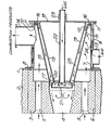
- the wall of a furnace in which the burner is mounted is formed as an outer metal skin 1 and an inner refractory lining 2.
- a refractory quarl block 3, having a central combustion chamber 4 and combustion products passageways 5, is supported within an aperture in the refractory lining 2 of the furnace wall.
- a cylindrical recuperator chamber 7 is detachably secured to the outer metal skin of the furnace wall by its inner flange 8 to which is attached a cylindrical outer sleeve 9 having an outer flange 11.
- the recuperator chamber 7 has an outer flange 12.
- An inlet 13 for combustion air is provided in the outer sleeve 9, and an exit 14 for combustion products passes through the outer sleeve'to communicate with the recuperator chamber.
- the combustion products side of the recuperator is completed by an outer conical recuperator tube 15 attached to the flange 12 of the recuperator chamber 7 by its flange 16 and supported within the combustion chamber 4 at 17.
- a backplate 18 carries an inner conical recuperator tube 19 and is attached to .the flange 11 of the outer sleeve 9 and to a rear part 20 of a burner nozzle 21.
- Fuel gas is supplied to the nozzle 21 through a central tube 22 which is supported through a boss 23 in the backplate 18.
- Ancillary equipment, e.g., for ignition and flame detection is incorporated but not shown.
- combustion products flow from the furnace through passageways 5 into the recuperator chamber 7 which they leave through exit 14.
- Combustion air driven by a fan (not shown), enters the burner at inlet 13 and passes through the passageway 24 between the wall of recuperator chamber 7 and sleeve 9 to enter the conical annular space 25 between the outer and inner conical recuperator tubes 15 and 19.
- the present invention has several advantages. Ease of maintenance is one and it arises not merely because the sevexal.components are separable but also because they can readily be disengaged. In known recuperative burners, distorted tubes can lock together so that it becomes necessary to cut through them before they can be withdrawn one from another. They cannot then be reassembled and must be replaced.
- the conical construction of the main part of the recuperator in accordance with the present invention eliminates the possibility of interlocking and in consequence the components, though they may have distorted, can more often be refurbished and re-used. Only severely damaged components need be replaced.
- Disengagement of the conical recuperator tube 15 from the quarl block 3 at 17, is straightforward because it is no longer necessary to provide a mechanical seal at the end of the combustion air passageway 25 to prevent leakage of air into the combustion products passageway 4. Instead, the low pressure region created around the nozzle 21 by the air flow into the combustion chamber 4 is made use of to ensure that leakage is always from the combustion products passageway 5 into the air passageway 25. Leakage in this direction is acceptable and can even be desirable in some applications. Moreover, because the inner structure of the recuperator now has to support less weight it is less likely to distort.
- the invention has the advantage of improved design flexibility, resulting in the main from the introduction of conically fitting components.
- the cone angle of the outer conical recuperator tube 15 may be varied to influence the proportion of heat exchanged between the combustion products and incoming combustion air that is transferred by radiation.
- a different cone angle may be used for the inner conical recuperator tube 19 to progressively alter the cross-sectional area of the annular space and influence the velocity of the air flow.
- the greater scope that these variations afford enables the designer to optimise the amount of air preheat for a specific application of the invention and to exercise some control over the distribution of heat transfer within the recuperator and hence over surface temperatures.
Landscapes
- Engineering & Computer Science (AREA)
- Chemical & Material Sciences (AREA)
- Combustion & Propulsion (AREA)
- Mechanical Engineering (AREA)
- General Engineering & Computer Science (AREA)
- Air Supply (AREA)
- Combustion Of Fluid Fuel (AREA)
- Gas Burners (AREA)
- Pre-Mixing And Non-Premixing Gas Burner (AREA)
Applications Claiming Priority (2)
| Application Number | Priority Date | Filing Date | Title |
|---|---|---|---|
| GB8027970A GB2082753B (en) | 1980-08-29 | 1980-08-29 | Recuperative burner |
| GB8027970 | 1980-08-29 |
Publications (2)
| Publication Number | Publication Date |
|---|---|
| EP0047568A1 true EP0047568A1 (de) | 1982-03-17 |
| EP0047568B1 EP0047568B1 (de) | 1984-03-28 |
Family
ID=10515723
Family Applications (1)
| Application Number | Title | Priority Date | Filing Date |
|---|---|---|---|
| EP81300012A Expired EP0047568B1 (de) | 1980-08-29 | 1981-01-05 | Rekuperativbrenner |
Country Status (7)
| Country | Link |
|---|---|
| US (1) | US4408983A (de) |
| EP (1) | EP0047568B1 (de) |
| JP (1) | JPS5773310A (de) |
| AU (1) | AU524720B2 (de) |
| CA (1) | CA1159353A (de) |
| DE (2) | DE3162841D1 (de) |
| GB (1) | GB2082753B (de) |
Cited By (3)
| Publication number | Priority date | Publication date | Assignee | Title |
|---|---|---|---|---|
| EP0233406A1 (de) * | 1985-12-18 | 1987-08-26 | British Gas plc | Rekuperativ-Brenner |
| RU2622357C1 (ru) * | 2015-12-24 | 2017-06-14 | Федеральное государственное бюджетное образовательное учреждение высшего профессионального образования "Сибирский государственный индустриальный университет" | Газовая плоскопламенная горелка со встроенным радиационным рекуператором |
| RU2624676C1 (ru) * | 2016-05-10 | 2017-07-05 | Федеральное государственное автономное образовательное учреждение высшего образования "Северный (Арктический) федеральный университет имени М.В. Ломоносова" (САФУ) | Рекуперативная горелка |
Families Citing this family (17)
| Publication number | Priority date | Publication date | Assignee | Title |
|---|---|---|---|---|
| JPS625012A (ja) * | 1985-06-28 | 1987-01-12 | Chugai Ro Kogyo Kaisha Ltd | 排熱回収バ−ナ |
| US4615674A (en) * | 1985-09-13 | 1986-10-07 | Wolverine Corporation | Incinerator system |
| US5049064A (en) * | 1987-08-06 | 1991-09-17 | Brian Wills | Burner with regenerative bed |
| US4954076A (en) * | 1989-07-28 | 1990-09-04 | Air Products And Chemicals, Inc. | Flame stabilized oxy-fuel recirculating burner |
| EP0797063A3 (de) * | 1996-03-19 | 1999-04-21 | Gautschi Electro-Fours SA | Verfahren zum Beheizen eines Industrieofens und Regenerator-Brenner-Modulsystem hierfür |
| US5984665A (en) * | 1998-02-09 | 1999-11-16 | Gas Research Institute | Low emissions surface combustion pilot and flame holder |
| DE10326951A1 (de) * | 2003-06-12 | 2005-01-13 | Aichelin Entwicklungszentrum Und Aggregatebau Gesellschaft Mbh | Rekuperatorbrenner und Rekuperator hierzu |
| US8483105B2 (en) * | 2003-10-15 | 2013-07-09 | Qualcomm Incorporated | High speed media access control |
| DE102006051138A1 (de) * | 2006-10-30 | 2008-05-08 | J. Eberspächer GmbH & Co. KG | Brennerbaugruppe |
| US20130019850A1 (en) * | 2011-07-22 | 2013-01-24 | Aerojet-General Corporation | Enhanced radiative transfer and heat recovery for combustion device |
| US9027331B2 (en) * | 2013-02-27 | 2015-05-12 | Tenneco Automotive Operating Company Inc. | Exhaust aftertreatment burner with preheated combustion air |
| US8991163B2 (en) | 2013-02-27 | 2015-03-31 | Tenneco Automotive Operating Company Inc. | Burner with air-assisted fuel nozzle and vaporizing ignition system |
| US8959902B2 (en) | 2013-02-27 | 2015-02-24 | Tenneco Automotive Operating Company Inc. | Exhaust treatment burner and mixer system |
| US9027332B2 (en) | 2013-02-27 | 2015-05-12 | Tenneco Automotive Operating Company Inc. | Ion sensor with decoking heater |
| US9534525B2 (en) | 2015-05-27 | 2017-01-03 | Tenneco Automotive Operating Company Inc. | Mixer assembly for exhaust aftertreatment system |
| RU2682202C1 (ru) * | 2018-05-08 | 2019-03-15 | Федеральное государственное автономное образовательное учреждение высшего образования "Северный (Арктический) федеральный университет имени М.В. Ломоносова" | Рекуперативно-горелочный блок |
| RU2682214C1 (ru) * | 2018-07-11 | 2019-03-15 | Федеральное государственное автономное образовательное учреждение высшего образования "Северный (Арктический) федеральный университет имени М.В. Ломоносова" | Рекуперативно-горелочный блок |
Citations (1)
| Publication number | Priority date | Publication date | Assignee | Title |
|---|---|---|---|---|
| DE2227036B2 (de) * | 1971-06-03 | 1977-05-26 | Black, Sivalls & Bryson Inc., Kansas City, Mo. (V.St.A.) | Gasbrenner |
Family Cites Families (12)
| Publication number | Priority date | Publication date | Assignee | Title |
|---|---|---|---|---|
| US2857961A (en) * | 1954-07-13 | 1958-10-28 | Brown Fintube Co | Oil burners |
| US3174526A (en) * | 1960-08-23 | 1965-03-23 | Linde Robert Albert Von | Atomizing burner unit |
| US3269448A (en) * | 1965-12-02 | 1966-08-30 | Fabricacion De Maquinas | Automatic liquid fuel burner control |
| GB1140449A (en) * | 1967-01-02 | 1969-01-22 | Hotwork Ltd | Improvements in or relating to burners for furnaces |
| AT287163B (de) * | 1967-08-17 | 1971-01-11 | Aichelin Fa J | Industriebrenner, vorzugsweise fuer gasfoermige brennstoffe, mit rekuperativer luftvorwaermung |
| GB1331427A (en) * | 1969-11-01 | 1973-09-26 | British Gas Corp | Recuperative burners |
| US3705784A (en) * | 1971-01-11 | 1972-12-12 | Burnham Corp | Liquid fuel burner having reduced thermal stress and rapid start-up time |
| DE2303280C2 (de) * | 1973-01-24 | 1982-07-29 | Robert von Dipl.-Ing. 8032 Gräfelfing Linde | Brenner für fließfähige Brennstoffe |
| US3826083A (en) * | 1973-07-16 | 1974-07-30 | Gen Motors Corp | Recirculating combustion apparatus jet pump |
| JPS5218233A (en) * | 1975-08-02 | 1977-02-10 | Kawasaki Heavy Ind Ltd | Burning gas circulation-type pre-combustion chamber |
| NL7801395A (nl) * | 1977-02-23 | 1978-08-25 | Foerenade Fabriksverken | Werkwijze en inrichting voor het verbranden van vloeibare, gasvormige of poedervormige brandstoffen. |
| CH622081A5 (de) * | 1977-06-17 | 1981-03-13 | Sulzer Ag |
-
1980
- 1980-08-29 GB GB8027970A patent/GB2082753B/en not_active Expired
-
1981
- 1981-01-05 EP EP81300012A patent/EP0047568B1/de not_active Expired
- 1981-01-05 DE DE8181300012T patent/DE3162841D1/de not_active Expired
- 1981-01-05 US US06/222,753 patent/US4408983A/en not_active Expired - Lifetime
- 1981-01-05 DE DE198181300012T patent/DE47568T1/de active Pending
- 1981-01-08 AU AU66073/81A patent/AU524720B2/en not_active Expired
- 1981-01-13 CA CA000368391A patent/CA1159353A/en not_active Expired
- 1981-08-19 JP JP56130037A patent/JPS5773310A/ja active Granted
Patent Citations (1)
| Publication number | Priority date | Publication date | Assignee | Title |
|---|---|---|---|---|
| DE2227036B2 (de) * | 1971-06-03 | 1977-05-26 | Black, Sivalls & Bryson Inc., Kansas City, Mo. (V.St.A.) | Gasbrenner |
Cited By (3)
| Publication number | Priority date | Publication date | Assignee | Title |
|---|---|---|---|---|
| EP0233406A1 (de) * | 1985-12-18 | 1987-08-26 | British Gas plc | Rekuperativ-Brenner |
| RU2622357C1 (ru) * | 2015-12-24 | 2017-06-14 | Федеральное государственное бюджетное образовательное учреждение высшего профессионального образования "Сибирский государственный индустриальный университет" | Газовая плоскопламенная горелка со встроенным радиационным рекуператором |
| RU2624676C1 (ru) * | 2016-05-10 | 2017-07-05 | Федеральное государственное автономное образовательное учреждение высшего образования "Северный (Арктический) федеральный университет имени М.В. Ломоносова" (САФУ) | Рекуперативная горелка |
Also Published As
| Publication number | Publication date |
|---|---|
| CA1159353A (en) | 1983-12-27 |
| GB2082753A (en) | 1982-03-10 |
| AU6607381A (en) | 1982-03-04 |
| DE47568T1 (de) | 1983-12-22 |
| EP0047568B1 (de) | 1984-03-28 |
| AU524720B2 (en) | 1982-09-30 |
| GB2082753B (en) | 1984-08-30 |
| DE3162841D1 (en) | 1984-05-03 |
| US4408983A (en) | 1983-10-11 |
| JPS5773310A (en) | 1982-05-08 |
| JPH02607B2 (de) | 1990-01-08 |
Similar Documents
| Publication | Publication Date | Title |
|---|---|---|
| EP0047568B1 (de) | Rekuperativbrenner | |
| US6089855A (en) | Low NOx multistage combustor | |
| EP2294336B1 (de) | Brenner mit geringem nox-ausstoss | |
| US4304549A (en) | Recuperator burner for industrial furnaces | |
| US4453913A (en) | Recuperative burner | |
| US4400151A (en) | Controlled flow, split stream burner assembly | |
| EP0328418B1 (de) | Strahlrohrbeheizter Ofen und Brennstoffverbrennungsverfahren | |
| US3688760A (en) | Radiant tube assembly | |
| US4210411A (en) | Self-recuperative burner | |
| US4156590A (en) | Combustion in a melting furnace | |
| PL128772B1 (en) | Industrial burner with air preheating | |
| CN114234227A (zh) | 低nox、高率、高温、分级再循环燃烧器和辐射管燃烧系统 | |
| US4060380A (en) | Furnace having burners supplied with heated air | |
| US6029647A (en) | Recuperative radiant tube with hot side vitiation | |
| EP0826926B1 (de) | Rekuperativer Strahlrohrbrenner mit Abgasrückführung auf der Abgasseite | |
| WO1997029326A1 (en) | Burner assembly with air stabilizer vane | |
| US4214866A (en) | Burner for high temperature combustion air | |
| EP0066570B1 (de) | Hochtemperaturbrenner | |
| CN110094732B (zh) | 一种高压降高风速低NOx排放的燃气燃烧器 | |
| JP2975245B2 (ja) | 竪型炉 | |
| US3468616A (en) | Burners for furnaces | |
| AU573863B2 (en) | Gas burner | |
| CN222047725U (zh) | 一种加热炉燃烧器 | |
| CN219510798U (zh) | 一种制氢转化炉燃烧器 | |
| RU201414U1 (ru) | Топка выносная для получения газообразного теплоносителя сжиганием газообразного топлива |
Legal Events
| Date | Code | Title | Description |
|---|---|---|---|
| PUAI | Public reference made under article 153(3) epc to a published international application that has entered the european phase |
Free format text: ORIGINAL CODE: 0009012 |
|
| AK | Designated contracting states |
Designated state(s): BE DE FR IT NL |
|
| 17P | Request for examination filed |
Effective date: 19820204 |
|
| ITF | It: translation for a ep patent filed | ||
| DET | De: translation of patent claims | ||
| GRAA | (expected) grant |
Free format text: ORIGINAL CODE: 0009210 |
|
| AK | Designated contracting states |
Designated state(s): BE DE FR IT NL |
|
| REF | Corresponds to: |
Ref document number: 3162841 Country of ref document: DE Date of ref document: 19840503 |
|
| ET | Fr: translation filed | ||
| BECH | Be: change of holder |
Free format text: 840328 *BRITISH GAS P.L.C. |
|
| PLBE | No opposition filed within time limit |
Free format text: ORIGINAL CODE: 0009261 |
|
| STAA | Information on the status of an ep patent application or granted ep patent |
Free format text: STATUS: NO OPPOSITION FILED WITHIN TIME LIMIT |
|
| 26N | No opposition filed | ||
| NLS | Nl: assignments of ep-patents |
Owner name: BRITISH GAS PLC TE LONDEN, GROOT-BRITTANNIE. |
|
| REG | Reference to a national code |
Ref country code: FR Ref legal event code: TP |
|
| ITTA | It: last paid annual fee | ||
| PGFP | Annual fee paid to national office [announced via postgrant information from national office to epo] |
Ref country code: FR Payment date: 19991213 Year of fee payment: 20 |
|
| PGFP | Annual fee paid to national office [announced via postgrant information from national office to epo] |
Ref country code: NL Payment date: 19991223 Year of fee payment: 20 |
|
| PGFP | Annual fee paid to national office [announced via postgrant information from national office to epo] |
Ref country code: DE Payment date: 19991227 Year of fee payment: 20 |
|
| PGFP | Annual fee paid to national office [announced via postgrant information from national office to epo] |
Ref country code: BE Payment date: 20000107 Year of fee payment: 20 |
|
| BE20 | Be: patent expired |
Free format text: 20010105 *BG PUBLIC LIMITED COMPANY |
|
| PG25 | Lapsed in a contracting state [announced via postgrant information from national office to epo] |
Ref country code: NL Free format text: LAPSE BECAUSE OF EXPIRATION OF PROTECTION Effective date: 20010105 |
|
| NLV7 | Nl: ceased due to reaching the maximum lifetime of a patent |
Effective date: 20010105 |