EP0047603A2 - Dispositif pour découper de la viande en tranches - Google Patents
Dispositif pour découper de la viande en tranches Download PDFInfo
- Publication number
- EP0047603A2 EP0047603A2 EP81303842A EP81303842A EP0047603A2 EP 0047603 A2 EP0047603 A2 EP 0047603A2 EP 81303842 A EP81303842 A EP 81303842A EP 81303842 A EP81303842 A EP 81303842A EP 0047603 A2 EP0047603 A2 EP 0047603A2
- Authority
- EP
- European Patent Office
- Prior art keywords
- meat
- bandsaw
- depth stop
- path
- cutting
- Prior art date
- Legal status (The legal status is an assumption and is not a legal conclusion. Google has not performed a legal analysis and makes no representation as to the accuracy of the status listed.)
- Granted
Links
Images

Classifications
-
- B—PERFORMING OPERATIONS; TRANSPORTING
- B26—HAND CUTTING TOOLS; CUTTING; SEVERING
- B26D—CUTTING; DETAILS COMMON TO MACHINES FOR PERFORATING, PUNCHING, CUTTING-OUT, STAMPING-OUT OR SEVERING
- B26D7/00—Details of apparatus for cutting, cutting-out, stamping-out, punching, perforating, or severing by means other than cutting
- B26D7/06—Arrangements for feeding or delivering work of other than sheet, web, or filamentary form
- B26D7/0641—Arrangements for feeding or delivering work of other than sheet, web, or filamentary form using chutes, hoppers, magazines
-
- B—PERFORMING OPERATIONS; TRANSPORTING
- B26—HAND CUTTING TOOLS; CUTTING; SEVERING
- B26D—CUTTING; DETAILS COMMON TO MACHINES FOR PERFORATING, PUNCHING, CUTTING-OUT, STAMPING-OUT OR SEVERING
- B26D1/00—Cutting through work characterised by the nature or movement of the cutting member or particular materials not otherwise provided for; Apparatus or machines therefor; Cutting members therefor
- B26D1/01—Cutting through work characterised by the nature or movement of the cutting member or particular materials not otherwise provided for; Apparatus or machines therefor; Cutting members therefor involving a cutting member which does not travel with the work
- B26D1/46—Cutting through work characterised by the nature or movement of the cutting member or particular materials not otherwise provided for; Apparatus or machines therefor; Cutting members therefor involving a cutting member which does not travel with the work having an endless band-knife or the like
-
- Y—GENERAL TAGGING OF NEW TECHNOLOGICAL DEVELOPMENTS; GENERAL TAGGING OF CROSS-SECTIONAL TECHNOLOGIES SPANNING OVER SEVERAL SECTIONS OF THE IPC; TECHNICAL SUBJECTS COVERED BY FORMER USPC CROSS-REFERENCE ART COLLECTIONS [XRACs] AND DIGESTS
- Y10—TECHNICAL SUBJECTS COVERED BY FORMER USPC
- Y10T—TECHNICAL SUBJECTS COVERED BY FORMER US CLASSIFICATION
- Y10T83/00—Cutting
- Y10T83/202—With product handling means
- Y10T83/2074—Including means to divert one portion of product from another
- Y10T83/2083—Deflecting guide
-
- Y—GENERAL TAGGING OF NEW TECHNOLOGICAL DEVELOPMENTS; GENERAL TAGGING OF CROSS-SECTIONAL TECHNOLOGIES SPANNING OVER SEVERAL SECTIONS OF THE IPC; TECHNICAL SUBJECTS COVERED BY FORMER USPC CROSS-REFERENCE ART COLLECTIONS [XRACs] AND DIGESTS
- Y10—TECHNICAL SUBJECTS COVERED BY FORMER USPC
- Y10T—TECHNICAL SUBJECTS COVERED BY FORMER US CLASSIFICATION
- Y10T83/00—Cutting
- Y10T83/202—With product handling means
- Y10T83/2092—Means to move, guide, or permit free fall or flight of product
- Y10T83/2192—Endless conveyor
-
- Y—GENERAL TAGGING OF NEW TECHNOLOGICAL DEVELOPMENTS; GENERAL TAGGING OF CROSS-SECTIONAL TECHNOLOGIES SPANNING OVER SEVERAL SECTIONS OF THE IPC; TECHNICAL SUBJECTS COVERED BY FORMER USPC CROSS-REFERENCE ART COLLECTIONS [XRACs] AND DIGESTS
- Y10—TECHNICAL SUBJECTS COVERED BY FORMER USPC
- Y10T—TECHNICAL SUBJECTS COVERED BY FORMER US CLASSIFICATION
- Y10T83/00—Cutting
- Y10T83/647—With means to convey work relative to tool station
- Y10T83/6492—Plural passes of diminishing work piece through tool station
-
- Y—GENERAL TAGGING OF NEW TECHNOLOGICAL DEVELOPMENTS; GENERAL TAGGING OF CROSS-SECTIONAL TECHNOLOGIES SPANNING OVER SEVERAL SECTIONS OF THE IPC; TECHNICAL SUBJECTS COVERED BY FORMER USPC CROSS-REFERENCE ART COLLECTIONS [XRACs] AND DIGESTS
- Y10—TECHNICAL SUBJECTS COVERED BY FORMER USPC
- Y10T—TECHNICAL SUBJECTS COVERED BY FORMER US CLASSIFICATION
- Y10T83/00—Cutting
- Y10T83/647—With means to convey work relative to tool station
- Y10T83/654—With work-constraining means on work conveyor [i.e., "work-carrier"]
- Y10T83/6545—With means to guide work-carrier in nonrectilinear path
- Y10T83/6547—About axis fixed relative to tool station
- Y10T83/6548—Infeed
- Y10T83/655—About vertical axis
- Y10T83/6552—Cut normal to axis
-
- Y—GENERAL TAGGING OF NEW TECHNOLOGICAL DEVELOPMENTS; GENERAL TAGGING OF CROSS-SECTIONAL TECHNOLOGIES SPANNING OVER SEVERAL SECTIONS OF THE IPC; TECHNICAL SUBJECTS COVERED BY FORMER USPC CROSS-REFERENCE ART COLLECTIONS [XRACs] AND DIGESTS
- Y10—TECHNICAL SUBJECTS COVERED BY FORMER USPC
- Y10T—TECHNICAL SUBJECTS COVERED BY FORMER US CLASSIFICATION
- Y10T83/00—Cutting
- Y10T83/707—By endless band or chain knife
- Y10T83/7195—Including means to adjust relationship between band and work-support surface
- Y10T83/722—By varying distance between band and work-support surface
Definitions
- This invention relates to apparatus for portioning meat and like comestible articles.
- an improved apparatus for portioning meat which comprises a bandsaw arranged with a horizontal cutting flight, a meat holder positioned above said flight for rotation about a vertical axis, the meat holder being adapted to hold meat to be portioned substantially vertically at a position spaced from said axis, means for rotating the meat holder about said axis, and a depth stop below said flight, whereby the meat to be portioned is fed across said flight while resting on the depth stop by rotation of the meat holder.
- the meat to be portioned is slidingly rotated over a table to an aperture therein through which the meat drops on to the depth stop, which is mounted in a stationary position beneath said aperture.
- a slice immediately above the depth stop is cut off by the bandsaw and is immediately separated from the main portion of meat rotating in the meat holder to enable said main meat portion to return to the table at the end of the aperture.
- the cut meat portion is fed out from below the table to an outlet chute.
- apparatus for portioning meat comprising a bandsaw arranged with a generally horizontal cutting flight, a meat holder, driving means for moving said meat holder, thereby in use to move the meat to be portioned in a path intersecting the cutting flight at a cutting station, a depth stop below the cutting flight for supporting such meat during its movement through the cutting station, means for moving said depth stop in a path of movement through the cutting station which corresponds to the path of movement of the meat being moved by the meat holder, said two movements being substantially synchronised, and separating means at a separating station downstream of the cutting station for separating a cut portion of meat for transport on the depth stop from a remaining portion of meat retained by the meat holder.
- risk of jamming is minimised by moving the cut meat portion in synchronism with the remaining meat portion away from the bandsaw, and splitting off the cut meat portion at a point downstream of the bandsaw.
- the path of movement of the depth stop diverges from the path of movement of the remaining portion of the meat in the region of the separating station.
- the meat holder is preferably driven to move the meat in a closed path which returns the remaining portion thereof from the separating station to the cutting station.
- the meat holder is mounted to rotate about a generally vertical axis to one side of the bandsaw, whereby the meat to be portioned is driven through the cutting station in a circular path.
- the depth stop moves at the cutting station in a circular path of movement corresponding to that of the meat and downstream of the cutting station diverges from said circular path in an arc of increased radius.
- the meat retained by the meat holder is supported on a stationary table. In the preferred machine, the depth stop is substantially flush with the surface of the table.
- the thickness of the cut meat portion is variable by adjustment of the relative levels of a bandsaw assembly and a meat holder and depth stop assembly. In the preferred machine, this means of adjustment enables the depth stop to be maintained in flush relationship with the table.
- the separating means preferably comprises a deflector positioned just below the level of the bandsaw cutting flight at the separating station.
- this deflector may have a ramp-like upper surface down which the remaining portion of the meat can slide, within the confines of the meat holder, laterally relative to the path of the moving depth stop.
- a detector may be provided to detect yielding of the deflector beyond a predetermined amount and thereby provide an output for power cut-off or alarm purposes. The detector will so yield, of course, if the cut portion of meat will not readily split off from the remaining meat portion, for example because a "rough" cut has occurred due to bone breakage or splintering or the like.
- the required yielding movement of the deflector may be afforded by a biassing spring, which may enable the deflector to move downwardly out of the path of the meat or swing inwardly about a vertical pivot axis out of the path of the meat.
- the deflector To enable the deflector to operate efficiently at differing thicknesses of cut, it is preferably mounted in fixed relationship to the bandsaw assembly. Alternatively, interchangeable deflectors of differing depths may be provided.
- the -he movable depth stop preferably comprises an endless conveyor, which may conveniently take the form of a slatted supporting surface adapted to conform to a curved path of movement in the plane of said surface, said slatted surface being driven from below by means of a flexible chain.
- the table has an elongated aperture accommodating the top run of the conveyor, the longitudinal edges of the table aperture having depending lipped flanges which are engaged by grooves in the end edges of the conveyor slats, whereby the top run of the conveyor is accurately guided along the table aperture flush with the surface of said table.
- a guard will be provided for the bandsaw and meat holder.
- said guard will have an openable panel to permit loading of the meat holder, and an interlock means being provided to interrupt the driven movement of the meat holder and depth stop when said panel is opened.
- a further interlock may be provided to interrupt the drive to the meat holder, depth stop and the bandsaw if any other part of the guard is removed.
- a sensor is preferably provided for detecting a defective bandsaw and acting when operated to interrupt the drive to the meat holder, depth stop and the bandsaw.
- Two meat holder, depth stop and bandsaw units may be accommodated within a single housing, utilising a common drive, at least in part, to the two bandsaws.
- the arrangement will be such that the swarf or meat dust generated at the respective cutting stations is thrown clear of both units (i.e. neither unit is positioned downstream of the other unit in the path of the ejected swarf), conveniently towards a downstream site at which a collecting bin may be located.
- a typical linear speed of movement of the bandsaw blade, for portioning most meats, is generally in the range 3000 to 6000 feet per minute.
- such a linear blade speed can result in the blade teeth becoming filled with frozen meat, as a result of which the saw may cease to function correctly.
- the blade of the bandsaw is exchangeable to substitute a blade of selected teeth pitch
- means are provided for adjusting the speed of the driving means for the meat holder and depth stop and for adjusting the linear speed of the bandsaw.
- a meat-type selector means is provided wherein indicators can be adjusted to select a type of meat and thereby automatically effect adjustment of the speed controls to suit the selected meat type.
- the apparatus can be operable with a high speed of meat advance, a reduced number of teeth per inch in the bandsaw blade and an increased linear speed of said blade. It is found that by using a linear blade speed of some 15,000 feet per minute with a tooth pitch of three teeth per inch and a feed rate of some thirty revolutions per minute of the cylindrical drum containing the hunks of meat to be portioned, high density compressed meat of some four to six inches diameter can be cut without difficulty.
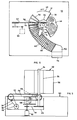
- a bandsaw 20 having a cutting flight 22 is mounted on a frame 24 within the base housing 10.
- the bandsaw is driven by an electric motor 26 and belt drive 28.
- the cutting flight 22 of the bandsaw is disposed at a level above the top surface of the base housing 10, which top surface constitutes a horizontal table 30.
- a meat cylinder assembly 32 is mounted over the table 30.
- This assembly has a vertical central shaft 34 on which is fixedly mounted a meat holder comprising a sleeve 36 from which project radial plate members 38 bent to form circumferential wings 40.
- the shaft 34 is drivable in rotation about its vertical axis by means of an electric motor 42 and transmission 44, It is to be noted that the lower edges of the meat holder formed by the elements 36, 38, 40 lie in a plane above the level of the cutting flight 22 of the bandsaw 20.
- the meat cylinder assembly 32 is driven in rotation so that the meat holder rotates above the table 30, whereby a joint of frozen meat 46 (see Figure 2) retained in each of the compartments of the meat holder is moved in a circular path, with the underside of the meat sliding on the table 30.
- This circular path of the meat 46 intersects the cutting flight 22 of the bandsaw 20, whereby a slice of meat will be cut off at the bottom of the joint, the thickness of the cut slice corresponding to the height of the cutting flight 22 above the table 30.
- Means are provided for varying the height of the bandsaw frame 24 relative to the table 30, thereby to adjust the thickness of the cut slice of meat.
- the table 30 In association with the path of movement of the meat in the meat cylinder assembly 32, the table 30 is formed with an elongate curved aperture 48 starting from just before the point where the meat is cut (the cutting station), extending in a circularly curved path matching that of the meat to a point beyond the cutting station, and then diverging from the path of the meat retained by the meat cylinder assembly 32, in an arc of increased radius, to the entrance 50 to an outlet chute 52.
- This aperture 48 in the table 30 is closed by a conveyor 54 flush with said table 30.
- This conveyor 54 in effect constitutes a moving depth stop for the meat.
- the starting point of the conveyor is referenced 56
- its curved portion through the cutting station is referenced 58
- its diverging portion of greater radius is referenced 60.
- the conveyor is of the slatted endless loop type, the individual slats 62 being linked in a manner which permits the conveyor to conform to the curved path of movement above described.
- the slats 62 are coupled to a driven chain 64 (see Figure 3), having a drive transmission 66 connected to the output of the motor 42 driving the meat cylinder assembly 32.
- Such a common drive for the meat cylinder assembly 32 and the moving depth stop 54 is not essential; however it facilitates the essential requirement for the moving depth stop 54 to be driven in synchronism with the meat 46 through the cutting station, so that there is no relative movement between the underside of said meat and the depth stop.
- the meat continues to move away from the cutting station with the remainder of the joint supported on the cut slice and without any relative movement therebetween tending to separate or split off the cut slice.
- a deflector or plough 68 is provided downstream of the cutting station to separate or split off the cut meat slice.
- the separating station thus defined is positioned adjacent the point of the conveyor 54 where the latter starts to diverge from the path of movement of the meat retained by the meat cylinder assembly 32 into an arc of greater radius, i.e. generally at the junction of the conveyor portions 58 and 60.
- the plough 68 is mounted to pivot, under the pressure of the cut meat slice, about a vertical axle 70, against the biassing action of a strong coil spring indicated at 72. Assuming the slice has been properly cut, it is pushed by the plough 68 outwardly of the path of movement of the remainder of the joint, to maintain the transport of the cut slice on the conveyor, which latter thus also serves as a take-off conveyor feeding the outlet chute 52.
- the plough 68 passes under the main meat joint and has its upper surface contoured generally in ramp-like form, as indicated at 74, to assist the downward and inward movement of the main meat joint, within the confines of the relevant compartment of the meat cylinder assembly 32, back on to the table 30.
- the meat cylinder assembly 32 retains the main joint and moves it around in a circular path back to the cutting station, ready for a further slice to be cut from the bottom of the joint.
- the depth of the plough 68 is such, as indicated in Figure 3, that it only presses on the cut slice of meat. It is, therefore, located at the level of the space between the bandsaw cutting flight 22 and the table 30.
- the plough 68 and its mounting means 70, 72 are preferably carried by the bandsaw frame 24 to be adjustable therewith relative to the table 30.
- the elongate aperture 48 in the table 30 has depending lipped flanges along its longitudinal edges, which lipped flanges are engaged by grooves or slots in the end edges of the conveyor slats, thereby both to ensure accurate guiding of the top run of the conveyor 54 along the required path and to ensure a flush relationship with the table 30.
- Loading of meat into the meat cylinder assembly 32 is effected through the panel 18 in the guard housing 16.
- the removal of this panel 18 automatically brakes the assembly 32 and conveyor 54 (while leaving the bandsaw running normally), thereby to enable the assembly 32 to be indexed round while successive compartments (which may number more than three depending on the nature of the primal cuts or joints of meat to be sliced) are loaded.
- Indexing can be effected manually or automatically.
- a further interlock may serve to cut off the power to the machine if any other section of the guard housing 16 is removed, while a bandsaw sensor may raise an audible or visual alarm responsive to stretching or breakage of the bandsaw.
- means is provided for adjusting the speed of rotation of the meat carousel on which the pieces of meat are mounted for cutting and means is provided for adjusting the linear speed of the bandsaw in the range 3000 to 30,000 feet per minute.
- a speed in the upper part of the range facilitates the portioning of dense, compressed meats.
- display means is provided in association with the speed controls and indicator means is provided operated by the speed controls which indicates the preferred speeds of operation for different types of meat, sizes of cut, densities, steaks (frozen or partially frozen etc.) and other related variables. By adjusting the controls so that the indicators point to the type etc. of meat concerned so the appropriate speeds of operation will automatically be selected.
- warning indicator means may be provided to indicate that the wrong pitch of blade is in use if a particular speed of feed or linear blade speed has been selected. Means is also provided for changing the blade easily and rapidly, more especially to substitute a blade of different teeth pitch.
- two units comprising meat cylinder assembly, bandsaw and moving depth stop may be contained within a single composite housing, the relative positioning of the units side-by-side being such that swarf or cut meat dust is thrown clear of both units to a downstream collecting bin.
Landscapes
- Life Sciences & Earth Sciences (AREA)
- Forests & Forestry (AREA)
- Engineering & Computer Science (AREA)
- Mechanical Engineering (AREA)
- Processing Of Meat And Fish (AREA)
- Meat, Egg Or Seafood Products (AREA)
Priority Applications (1)
| Application Number | Priority Date | Filing Date | Title |
|---|---|---|---|
| AT81303842T ATE12905T1 (de) | 1980-09-04 | 1981-08-24 | Scheibenschneidmaschine fuer fleisch. |
Applications Claiming Priority (4)
| Application Number | Priority Date | Filing Date | Title |
|---|---|---|---|
| GB8028634A GB2082967B (en) | 1980-09-04 | 1980-09-04 | A machine for portioning meat |
| GB8028634 | 1980-09-04 | ||
| GB8115516A GB2098539B (en) | 1981-05-20 | 1981-05-20 | Meat portioning using a bandsaw |
| GB8115516 | 1981-05-20 |
Publications (3)
| Publication Number | Publication Date |
|---|---|
| EP0047603A2 true EP0047603A2 (fr) | 1982-03-17 |
| EP0047603A3 EP0047603A3 (en) | 1983-06-29 |
| EP0047603B1 EP0047603B1 (fr) | 1985-04-24 |
Family
ID=26276788
Family Applications (1)
| Application Number | Title | Priority Date | Filing Date |
|---|---|---|---|
| EP19810303842 Expired EP0047603B1 (fr) | 1980-09-04 | 1981-08-24 | Dispositif pour découper de la viande en tranches |
Country Status (6)
| Country | Link |
|---|---|
| US (1) | US4420997A (fr) |
| EP (1) | EP0047603B1 (fr) |
| AU (1) | AU539857B2 (fr) |
| CA (1) | CA1171764A (fr) |
| DE (1) | DE3170132D1 (fr) |
| NZ (1) | NZ198261A (fr) |
Cited By (2)
| Publication number | Priority date | Publication date | Assignee | Title |
|---|---|---|---|---|
| NL1002794C2 (nl) * | 1996-04-04 | 1997-10-07 | Perugia B V | Snijmachine voor het snijden van vleeswaren en dergelijke produkten. |
| CN110919715A (zh) * | 2019-12-23 | 2020-03-27 | 俞欢凤 | 固化污泥处理用级进切料装置 |
Families Citing this family (9)
| Publication number | Priority date | Publication date | Assignee | Title |
|---|---|---|---|---|
| GB8723647D0 (en) * | 1987-10-08 | 1987-11-11 | Whitehouse J A | Sizing & cutting apparatus |
| WO1991009531A1 (fr) * | 1989-12-22 | 1991-07-11 | Dyer Jerry M | Procede et appareil de coupe en tranches de viande |
| US5881619A (en) * | 1993-06-22 | 1999-03-16 | United Technologies Corporation | Method and apparatus for cutting blocks of solid energetic materials |
| IT1305994B1 (it) * | 1998-05-28 | 2001-05-23 | Meta Meccanica S R L | Macchina affettatrice continua con lama rotante in un pianoorizzontale. |
| US6612920B1 (en) | 2000-02-11 | 2003-09-02 | Hormel Foods, Llc | Optimized loin saw |
| US7373217B2 (en) * | 2003-04-08 | 2008-05-13 | Hormel Foods, Llc | Apparatus for slicing a food product and method therefore |
| DE102004018978A1 (de) * | 2004-04-20 | 2005-11-17 | Thomas Warnke | Schneidemaschine |
| US7214403B1 (en) | 2005-09-07 | 2007-05-08 | Hbh Limited Partnership | Ham product and method for production thereof |
| CN113207935B (zh) * | 2021-03-03 | 2022-11-25 | 芜湖燕大润伟机械科技有限公司 | 基于类型解析的自适应机械加工系统及方法 |
Family Cites Families (8)
| Publication number | Priority date | Publication date | Assignee | Title |
|---|---|---|---|---|
| US3314461A (en) * | 1963-04-10 | 1967-04-18 | Bettcher Louis A | Frozen meat slicer having transmission with irrational ratio |
| US3428102A (en) * | 1965-10-13 | 1969-02-18 | Worthington Foods Inc | Slicing machine with slice arranger |
| US3867858A (en) * | 1973-07-30 | 1975-02-25 | Gorton Corp | Frozen fish cutter |
| US3972256A (en) * | 1975-05-30 | 1976-08-03 | Ross Henry M | Meat slicer |
| US4050339A (en) * | 1976-01-07 | 1977-09-27 | Soleri Richard A | Automatic carousel-type meat cutting machine |
| US4299150A (en) * | 1979-05-31 | 1981-11-10 | General Mills, Inc. | Method and apparatus for severing portions from a plurality of frozen columns of fish or the like |
| ATE8855T1 (de) * | 1980-06-24 | 1984-08-15 | Aew Engineering Company Limited | Fleischschneidmaschine. |
| US4356746A (en) * | 1980-06-30 | 1982-11-02 | Aew Engineering Co., Ltd. | Apparatus for portioning meat |
-
1981
- 1981-08-24 DE DE8181303842T patent/DE3170132D1/de not_active Expired
- 1981-08-24 EP EP19810303842 patent/EP0047603B1/fr not_active Expired
- 1981-08-31 US US06/297,747 patent/US4420997A/en not_active Expired - Fee Related
- 1981-09-02 CA CA000385075A patent/CA1171764A/fr not_active Expired
- 1981-09-03 AU AU74903/81A patent/AU539857B2/en not_active Ceased
- 1981-09-03 NZ NZ198261A patent/NZ198261A/en unknown
Cited By (3)
| Publication number | Priority date | Publication date | Assignee | Title |
|---|---|---|---|---|
| NL1002794C2 (nl) * | 1996-04-04 | 1997-10-07 | Perugia B V | Snijmachine voor het snijden van vleeswaren en dergelijke produkten. |
| CN110919715A (zh) * | 2019-12-23 | 2020-03-27 | 俞欢凤 | 固化污泥处理用级进切料装置 |
| CN110919715B (zh) * | 2019-12-23 | 2021-12-03 | 邳州市景鹏创业投资有限公司 | 固化污泥处理用级进切料装置 |
Also Published As
| Publication number | Publication date |
|---|---|
| AU7490381A (en) | 1982-03-11 |
| CA1171764A (fr) | 1984-07-31 |
| NZ198261A (en) | 1984-05-31 |
| EP0047603A3 (en) | 1983-06-29 |
| EP0047603B1 (fr) | 1985-04-24 |
| US4420997A (en) | 1983-12-20 |
| AU539857B2 (en) | 1984-10-18 |
| DE3170132D1 (en) | 1985-05-30 |
Similar Documents
| Publication | Publication Date | Title |
|---|---|---|
| EP0047603B1 (fr) | Dispositif pour découper de la viande en tranches | |
| CS244832B2 (en) | Cutter | |
| ES8405291A1 (es) | Perfeccionamientos en los aparatos para desmenuzar productos alimenticios | |
| US4813317A (en) | Rotary slicing machine | |
| EP1436127B1 (fr) | Dispositif et procede pour couper de la viande | |
| US4420118A (en) | Cauliflower size cutter | |
| US4817245A (en) | Meat saw and method of processing meat | |
| GB2082967A (en) | A machine for portioning meat | |
| US4241096A (en) | Method for coring cauliflower heads | |
| US4352325A (en) | Apparatus for processing whole beets | |
| US3548902A (en) | Apparatus for producing mixed subdivided food material | |
| EP0245277B1 (fr) | Appareil servant a enlever la peau d'une demi-pomme de terre | |
| US3631908A (en) | Automatic meat-cutting machine | |
| US4356746A (en) | Apparatus for portioning meat | |
| US2519985A (en) | Cutting machine | |
| EP0042462B1 (fr) | Dispositif pour couper de la viande | |
| US3122189A (en) | Onion top and root trimmer | |
| US1818245A (en) | Slicing machine | |
| US2223542A (en) | Food dicing apparatus | |
| EP0586721B1 (fr) | Procédé à trancher | |
| US3858470A (en) | French and italian bread slicer | |
| CN223477854U (zh) | 一种自适应果蔬加工用切片机 | |
| US3157213A (en) | Animal carcass trimming machine | |
| CA1130178A (fr) | Machine a debiter la viande | |
| SU1200874A1 (ru) | Устройство дл разрезани м сных туш |
Legal Events
| Date | Code | Title | Description |
|---|---|---|---|
| PUAI | Public reference made under article 153(3) epc to a published international application that has entered the european phase |
Free format text: ORIGINAL CODE: 0009012 |
|
| AK | Designated contracting states |
Designated state(s): AT BE CH DE FR IT LU NL SE |
|
| PUAL | Search report despatched |
Free format text: ORIGINAL CODE: 0009013 |
|
| AK | Designated contracting states |
Designated state(s): AT BE CH DE FR IT LI LU NL SE |
|
| 17P | Request for examination filed |
Effective date: 19831001 |
|
| ITF | It: translation for a ep patent filed | ||
| GRAA | (expected) grant |
Free format text: ORIGINAL CODE: 0009210 |
|
| AK | Designated contracting states |
Designated state(s): AT BE CH DE FR IT LI LU NL SE |
|
| PG25 | Lapsed in a contracting state [announced via postgrant information from national office to epo] |
Ref country code: NL Effective date: 19850424 Ref country code: LI Effective date: 19850424 Ref country code: CH Effective date: 19850424 Ref country code: BE Effective date: 19850424 Ref country code: AT Effective date: 19850424 |
|
| REF | Corresponds to: |
Ref document number: 12905 Country of ref document: AT Date of ref document: 19850515 Kind code of ref document: T |
|
| REF | Corresponds to: |
Ref document number: 3170132 Country of ref document: DE Date of ref document: 19850530 |
|
| ET | Fr: translation filed | ||
| REG | Reference to a national code |
Ref country code: CH Ref legal event code: PL |
|
| PG25 | Lapsed in a contracting state [announced via postgrant information from national office to epo] |
Ref country code: LU Free format text: LAPSE BECAUSE OF NON-PAYMENT OF DUE FEES Effective date: 19850831 |
|
| NLV1 | Nl: lapsed or annulled due to failure to fulfill the requirements of art. 29p and 29m of the patents act | ||
| PLBE | No opposition filed within time limit |
Free format text: ORIGINAL CODE: 0009261 |
|
| STAA | Information on the status of an ep patent application or granted ep patent |
Free format text: STATUS: NO OPPOSITION FILED WITHIN TIME LIMIT |
|
| 26N | No opposition filed | ||
| PG25 | Lapsed in a contracting state [announced via postgrant information from national office to epo] |
Ref country code: SE Effective date: 19890825 |
|
| ITTA | It: last paid annual fee | ||
| PG25 | Lapsed in a contracting state [announced via postgrant information from national office to epo] |
Ref country code: FR Effective date: 19900427 |
|
| PG25 | Lapsed in a contracting state [announced via postgrant information from national office to epo] |
Ref country code: DE Effective date: 19900501 |
|
| REG | Reference to a national code |
Ref country code: FR Ref legal event code: ST |
|
| EUG | Se: european patent has lapsed |
Ref document number: 81303842.9 Effective date: 19900418 |