EP0047666A2 - Videosignal-Wiedergabegerät - Google Patents
Videosignal-Wiedergabegerät Download PDFInfo
- Publication number
- EP0047666A2 EP0047666A2 EP81304100A EP81304100A EP0047666A2 EP 0047666 A2 EP0047666 A2 EP 0047666A2 EP 81304100 A EP81304100 A EP 81304100A EP 81304100 A EP81304100 A EP 81304100A EP 0047666 A2 EP0047666 A2 EP 0047666A2
- Authority
- EP
- European Patent Office
- Prior art keywords
- signal
- circuit
- phase
- track
- reproducing head
- Prior art date
- Legal status (The legal status is an assumption and is not a legal conclusion. Google has not performed a legal analysis and makes no representation as to the accuracy of the status listed.)
- Granted
Links
Images



Classifications
-
- H—ELECTRICITY
- H04—ELECTRIC COMMUNICATION TECHNIQUE
- H04N—PICTORIAL COMMUNICATION, e.g. TELEVISION
- H04N9/00—Details of colour television systems
- H04N9/79—Processing of colour television signals in connection with recording
- H04N9/87—Regeneration of colour television signals
- H04N9/873—Regeneration of colour television signals for restoring the colour component sequence of the reproduced chrominance signal
Definitions
- the invention relates to a video signal reproducing apparatus having a circuit device for detecting correctly one of the color difference signals of a color subcarrier signal contained in a PAL or SECAM color television signal reproduced from a recorded medium by the system.
- the recording format commonly named the "C-format” has been proposed as the SMPTE standard for video tape recorders for broadcasting use.
- C-format The recording format commonly named the "C-format”
- T indicates the recorded tracks
- -2, -1, O, 1 and 2 are track numbers
- X shows the direction of movement of the magnetic tape
- W shows the direction of scanning by a magnetic head.
- one frame period of a PAL color television signal contains 625 line periods, during which the phase of the R-Y component of the color subcarrier signal is shifted by 180 degrees at every line period so as to be +(R-Y) and -(R-Y) in alternate line periods and adjacent recorded tracks are formed with a line period alignment (H alignment) with a difference of 3.5 line periods between mutually corresponding line periods on two successive recorded tracks, if +(R-Y) and -(R-Y) are represented as "0" and "E", respectively, the "O" and the "E” face each other on each two successive recorded tracks.
- H alignment line period alignment
- a SECAM color television signal is recorded on magnetic tape by such a video tape recorder in a recording pattern as shown in Figure 1 and reproduced from the tape it is also necessary in the time base corrector to distinguish correctly between R-Y and B-Y components of the reproduced color subcarrier signal for the same reason as mentioned above in the case of the PAL color television signal.
- reference numeral 1 stands for an input terminal to which the color video signal reproduced from the tape is supplied as an input signal; 2 for a synchronizing signal separating circuit for extracting a synchronizing signal and a burst signal from the reproduced color video signal; 3 for an automatic frequency control circuit; 4 for an automatic phase control circuit; 5 for a subcarrier phase detecting circuit; 6 for an inertial circuit comprising a comparing and inverting signal producing circuit 7 and a divider 8; and 9 for an output terminal.
- a horizontal sync signal H and the burst signal S B are extracted from the color video signal supplied to the input terminal 1 by the sync signal separating circuit 2.
- a horizontal scanning signal f H and a subcarrier signal f sc are generated using the horizontal sync signal H as a reference in the automatic frequency control circuit 3.
- the phase of the subcarrier signal f SC is not yet fixed at the output of the automatic frequency control circuit 3 but is fixed at the automatic phase control circuit 4 so as to have the same phase as the burst signal S which is also supplied to the automatic phase control circuit 4.
- the subcarrier signal having its phase locked by the burst signal S B is shown as f' SC and this subcarrier signal f' SC is supplied to the subcarrier phase detecting circuit 5 where the level of the subcarrier signal f' SC is discriminated between "H” or "L” at the repetitive periods determined by the burst signal S B ; that is, the "0" or the "E” as mentioned above is detected as disclosed in detail later.
- the frequency of the horizontal scanning signal f is divided by two by the divider 8 and appears at the output terminal 9 as an output signal.
- the frequency-divided horizontal scanning signal is also supplied to the comparing and inverting signal producing circuit 7 and compared in phase with the output of the subcarrier phase detecting circuit 5.
- the circuit 7 produces an inverting signal and supplies it to the divider 8 when the phase of the divided horizontal scanning signal does not coincide with the phase of the output of the subcarrier phase detecting circuit 5.
- the phase of the output of the divider 8. is inverted by the inverting signal supplied to the divider 8 and, as a result, the phase of the output signal obtained at the output terminal 9 is corrected. Even if the input signal supplied to the input terminal 1 is momentarily interrupted due to a drop out of the reproduced color video signal or the input signal does not contain the burst signal S B momentarily at the period of vertical synchronous signal, the inertial circuit 6 is operative to hold the phase information obtained prior to such a momentary interruption.
- the circuit shown in Figure 3 can be used as the inertial circuit 6 in Figure 2, for example.
- 7A is an exclusive OR circuit and 7B is a counter, and they together form the comparing and inverting signal generating circuit 7.
- the exclusive OR circuit 7A produces its output and the counter 7B is reset with the output of the exclusive OR circuit 7A.
- the counter 7B is not reset but continues to count at every line period each pulse of the horizontal scanning signal f H and produces the inverting signal to invert the phase of the output of the divider 8 when the cumulative count reaches a preset value. Consequently, the correction in the phase of the output signal obtained at the output terminal 9 is done with a lag of plural line periods corresponding to the preset value for the counter 7B.
- Figure 4 shows one example of the subcarrier phase detecting circuit 5 shown in Figure 2.
- 5A is a delay circuit which is operative to delay the subcarrier signal f' SC by one line period regardless of variations in frequency of the subcarrier signal f' SC
- 5B is a sample and hold circuit which detects the phase of the output of the delay circuit 5A at the leading or trailing edge of the burst signal S B .
- the levels of the delayed subcarrier signal having phases shown as (A'), (B') and (C') detected at each falling edge of the burst signal S B take "H", "L”, "H", --- in each successive line period, and it is understood that when the detected level is "H", the burst signal S B has the phase which corresponds to the phase -(R-Y) of the R-Y component, that is, the phase of the R-Y component in the reproduced color video signal at that time is -(R-Y), and when the detected level is "L”, the burst signal S B has the phase which corresponds to the phase +(R-Y) of the R-Y component, that is, the phase of the R-Y component in the reproduced color video signal at that time is +(R-Y). Since the burst signal S B extracted from the reproduced color video signal at the synchronous signal separating circuit
- a head tracking control system commonly called Automatic Scan Tracking (AST) or Dynamic Tracking (DT) has been employed in the video tape recorder.
- AST Automatic Scan Tracking
- DT Dynamic Tracking
- a rotary reproducing head is attached to a certain edge portion of a plate made of piezoelectric ceramics which is commonly called a "bimorph”, and is moved in the direction perpendicular to the recorded tracks on the tape or to the scanning direction of the head so that the head correctly follows the recorded tracks; it will be appreciated that when scanning at a tape speed different from the recording speed the head motion is not parallel to the tracks.
- the present invention is intended to remedy the defect just mentioned relating to the previously proposed video tape recorder.
- a video signal reproducing apparatus for reproducing signals recorded along a plurality of tracks disposed in side by side relation on a record medium using a reproducing head adapted for scanning motion relative to the tracks, the apparatus comprising a moving device for moving the reproducing head in the direction substantially perpendicular to its scanning direction, a control circuit for controlling said moving device to make said reproducing head scan on a selected recorded track, and a color information producing circuit for obtaining information about the phase of a color signal component at every line period from the output of the reproducing head, characterised by an error prevention circuit for preventing the output of said color information producing circuit from being in error in response to information about said selected recorded track.
- the video tape recorder employing the AST or DT head tracking control is provided with a detecting circuit for detecting the condition of the above mentioned "+ 2 N " before the movement of the reproducing head into the track with the number "+ 2N” from the track with the number "O” in order to supply with an appropriate control voltage to the bimorph to which the reproducing head is attached.
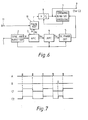
- FIG. 6 shows part of one embodiment of the present invention.
- a pulse adding circuit 10 is provided between the automatic frequency control circuit 3 and the divider 8, and 11 is a control terminal to which a detected signal obtained in relation to "+ 2N" is supplied; that is the input terminal 11 receives a pulse when a track jump of + 2N"tracksis about to occur.
- the remaining portions are the same as the circuit device shown in Figure 2.
- the output of the automatic frequency control circuit 3 supplied to the pulse adding circuit 10 is shown at A in Figure 7 and, on the basis of this output, the output signal shown at C 1 in Figure 7 is obtained at the output terminal 9.
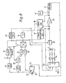
- FIG. 8 there is shown: a reproducing head 21; a moving device 22 utilizing, for example, a bimorph for moving the reproducing head 21 in the direction perpendicular to the recorded tracks on the tape or to its scanning direction; a vibration detector 23 such as a strain gauge for detecting the vibration of the moving device 22; a frequency discriminator 24 for demodulating the output of the reproducing head 21, the demodulated output from which is carried forward as the reproduced color video signal and simultaneously used for extracting the sync signal therefrom in the system; a horizontal sync signal separating circuit 25; a vertical sync signal separating circuit 26; an amplitude detector 27 for detecting the envelope of the output of the reproducing head 21; a sample and hold circuit 28 for sampling and holding the respective level of the said envelope at times corresponding to each horizontal sync signal 27; band pass filters 29
- the circuit including the above mentioned parts 24, 25, 37, 39 and 41 detects the information regarding the inclination of the recorded track to produce a control signal in response to the degree of the inclination of the recorded track and controls slanting movement of the moving device 22 to make the reproducing head 21 scan accurately on the recorded track.
- This circuit connection is operative to achieve quick scanning angle correction particularly in response to rapid variations in the running speed of the tape.
- the parts 27, 28, 29, 23, 30, 31, 32, 38, 39 and 40 form a tracking servo control loop in which the moving device 22 is vibrated to make the reproducing head 21 follow the track deviations detected from the mutual relation between the waveforms of vibrations of the reproducing head 21 and variations in the reproduced color video signal.
- parts 26, 33, 34, 35 and 36 determine the direction and length of skip movement of the reproducing head in accordance with the interval between successive pulses of the reproduced horizontal sync signal and the phase of the vertical sync signal, and drive the moving device 22 to give the skip movement to the reproducing head 21.
- Figure 9 shows the tracing pattern over the tape described by the reproducing head when the ratio ri:l of replay to recording speed is 2.25:1, that is, when replaying the tape with the tape speed multiplied by 2025 and Figure 10 shows the deviations of the bimorph employed in the moving device 22 in the tracing situation shown in Figure 9, which corresponds to the waveform of a bimorph driving voltage.
- the moving device 22 is supplied with an inclination correcting voltage so as to have an inclination correction to deviate the reproducing head 21 by 1.25 track pitches during each scanning period for one track.
- the moving device 22 since the scanning on the track with a skip with a minimum length of 1 track pitch is performed, it is necessary for the moving device 22 to have a track jump to deviate the reproducing head from the end portion of a certain track to the beginning portion of the next track as shown in Figure 10, and the moving device 22 is supplied also with a flyback voltage so as to achieve the track jump.
- the pitch of the track jump depends on the ratio n:l of tape replay to tape recording speed, and when n is not integer, one obtains the equation where n + 1>1>n>m>n - 1, and x, y, 1 and m are integers, x and y being the number of of times the same tracks are scanned, and two integers 1 and m in this equation represent the jump pitches. For example, when n equals 2.25, 1, m, x and y equal 3, 2, 1 and 3, respectively. Consequently, in this example, first a track jump of three track pitches is performed once and then a track jump of two track pitches is performed three times repeatedly.
- the condition for selecting the above mentioned flyback m and m - 1 is determined as described below.
- the moving device 22 is required to be deviated by a distance corresponding to the inclination correction for
- the direction and length of skip movement is determined by the jump logic circuit 33 in Figure 8 and the skip movement of the reproducing head 21 is performed.
- the reproducing head jumps to the track "+ 2n"
- phase error is caused due to the line period alignment with a difference of 3.5 line periods between mutually corresponding line periods on two successive tracks
- FIG. 11 shows part of another embodiment of the present invention which is intended to correctly detect the phase of the R-Y component of the SECAM color television signal, in the same manner as Figure 6.
- the detected signal obtained in relation to "+ 2n” is utilized for correct phase detection in the above disclosed embodiments, it is generally possible to utilize a detected signal obtained in relation to "+ 2n + 1" with the same result.
- the pulse adding circuit 10 is set to operate with the detected signal obtained in relation to "+ 2n” so as to add one pulse to the input of the divider 8 in the circuit devices shown in Figure 6 and Figure 11, it is also possible to use the detected signal obtained in relation to "+ 2n + 1" and set the pulse adding circuit 10 so as not to operate when the detected signal obtained in relation to "+ 2n + 1" is supplied thereto.
- the reproducing head provided for scanning the recorded tracks on which the color video signal is recorded is moved in the direction substantially perpendicular to its scanning direction so as to scan a selected recorded track and the information about the phase of the color signal component is obtained at every line period from the reproduced video signal, the information about the selected recorded track to be scanned by the reproducing head is utilized for preventing the information about the phase of the color signal component from being in error, and, therefore, the time delay as caused in the prior art by, for example, the inertial circuit and so on can be avoided and the correct information about the phase of color signal component is reliably obtained.
Landscapes
- Engineering & Computer Science (AREA)
- Multimedia (AREA)
- Signal Processing (AREA)
- Adjustment Of The Magnetic Head Position Track Following On Tapes (AREA)
- Television Signal Processing For Recording (AREA)
- Signal Processing Not Specific To The Method Of Recording And Reproducing (AREA)
Priority Applications (1)
| Application Number | Priority Date | Filing Date | Title |
|---|---|---|---|
| AT81304100T ATE14360T1 (de) | 1980-09-09 | 1981-09-08 | Videosignal-wiedergabegeraet. |
Applications Claiming Priority (2)
| Application Number | Priority Date | Filing Date | Title |
|---|---|---|---|
| JP125080/80 | 1980-09-09 | ||
| JP55125080A JPS5750189A (en) | 1980-09-09 | 1980-09-09 | Magnetic recording and playback device |
Publications (3)
| Publication Number | Publication Date |
|---|---|
| EP0047666A2 true EP0047666A2 (de) | 1982-03-17 |
| EP0047666A3 EP0047666A3 (en) | 1983-03-30 |
| EP0047666B1 EP0047666B1 (de) | 1985-07-17 |
Family
ID=14901329
Family Applications (1)
| Application Number | Title | Priority Date | Filing Date |
|---|---|---|---|
| EP81304100A Expired EP0047666B1 (de) | 1980-09-09 | 1981-09-08 | Videosignal-Wiedergabegerät |
Country Status (4)
| Country | Link |
|---|---|
| EP (1) | EP0047666B1 (de) |
| JP (1) | JPS5750189A (de) |
| AT (1) | ATE14360T1 (de) |
| DE (1) | DE3171399D1 (de) |
Family Cites Families (9)
| Publication number | Priority date | Publication date | Assignee | Title |
|---|---|---|---|---|
| NZ148765A (de) * | 1966-05-13 | |||
| GB1156865A (en) * | 1967-01-27 | 1969-07-02 | Rca Corp | Identification Circuit for PAL System Conversion of Tape. |
| JPS5143733B2 (de) * | 1971-08-30 | 1976-11-24 | ||
| IT1009413B (it) * | 1974-04-03 | 1976-12-10 | Indesit | Circuito elaboratore di segnali cromatici televisivi |
| JPS5750117B2 (de) * | 1974-11-05 | 1982-10-26 | ||
| GB1541228A (en) * | 1975-05-20 | 1979-02-28 | Rca Corp Pal | Alternate line colour phase detector |
| JPS5538649A (en) * | 1978-09-07 | 1980-03-18 | Sony Corp | Tracking unit of magnetic head |
| JPS5542482A (en) * | 1978-09-19 | 1980-03-25 | Sanyo Electric Co Ltd | Color signal circuit of pal color television receiver |
| JPS6059792B2 (ja) * | 1978-11-30 | 1985-12-26 | ソニー株式会社 | カラ−映像信号処理装置 |
-
1980
- 1980-09-09 JP JP55125080A patent/JPS5750189A/ja active Granted
-
1981
- 1981-09-08 EP EP81304100A patent/EP0047666B1/de not_active Expired
- 1981-09-08 AT AT81304100T patent/ATE14360T1/de not_active IP Right Cessation
- 1981-09-08 DE DE8181304100T patent/DE3171399D1/de not_active Expired
Also Published As
| Publication number | Publication date |
|---|---|
| JPH0154917B2 (de) | 1989-11-21 |
| EP0047666B1 (de) | 1985-07-17 |
| EP0047666A3 (en) | 1983-03-30 |
| JPS5750189A (en) | 1982-03-24 |
| ATE14360T1 (de) | 1985-08-15 |
| DE3171399D1 (en) | 1985-08-22 |
Similar Documents
| Publication | Publication Date | Title |
|---|---|---|
| US4528605A (en) | Rotary magnetic head scanning control system in a magnetic recording and reproducing apparatus | |
| EP0102809B1 (de) | Magnetisches Wiedergabegerät | |
| CA1115410A (en) | Electronic time base error correction methods and arrangements | |
| JPS634387B2 (de) | ||
| US4485395A (en) | Misregistration prevention in two channel VTRS | |
| EP0054419B1 (de) | Spurlageüberwachungsanordnung in einer magnetischen Aufzeichnungs- und Wiedergabeeinrichtung | |
| CA1118886A (en) | Automatic tracking for a videotape recorder | |
| EP0627731B1 (de) | Wiedergabegerät mit Spurnachführungsmitteln | |
| US4034397A (en) | Pilot signal luminance correction means for video recording apparatus | |
| US4137547A (en) | Drop-out responsive magnetic recording and reproducing system | |
| CA1160337A (en) | Tracking control system | |
| EP0043739B1 (de) | Nachführsystem | |
| EP0227468A2 (de) | Aufnahme- und/oder Wiedergabegerät | |
| EP0047666B1 (de) | Videosignal-Wiedergabegerät | |
| US3934264A (en) | Videotape recorder and reproducer every line velocity compensator apparatus | |
| US5218447A (en) | Method and apparatus for identifying the reproduction mode of a video tape recorder | |
| EP0475750B1 (de) | Videobandaufzeichnungsgerät | |
| KR910000569B1 (ko) | 트래킹에러신호의 작성회로 | |
| US5083228A (en) | Tracking error detecting circuit | |
| CA1169551A (en) | Pal burst switching angle error cancellation | |
| EP0081232B1 (de) | Verfahren und Vorrichtung zur Erfassung von Spurwechselpunkten in magnetischen Aufzeignungs- und Wiedergabesystemen | |
| JPH0223119B2 (de) | ||
| JPS6130338B2 (de) | ||
| JP2668177B2 (ja) | 磁気記録再生装置 | |
| JP2626050B2 (ja) | 回転ヘッド型再生装置 |
Legal Events
| Date | Code | Title | Description |
|---|---|---|---|
| PUAI | Public reference made under article 153(3) epc to a published international application that has entered the european phase |
Free format text: ORIGINAL CODE: 0009012 |
|
| AK | Designated contracting states |
Designated state(s): AT DE FR GB NL |
|
| 17P | Request for examination filed |
Effective date: 19820910 |
|
| PUAL | Search report despatched |
Free format text: ORIGINAL CODE: 0009013 |
|
| AK | Designated contracting states |
Designated state(s): AT DE FR GB NL |
|
| GRAA | (expected) grant |
Free format text: ORIGINAL CODE: 0009210 |
|
| AK | Designated contracting states |
Designated state(s): AT DE FR GB NL |
|
| REF | Corresponds to: |
Ref document number: 14360 Country of ref document: AT Date of ref document: 19850815 Kind code of ref document: T |
|
| REF | Corresponds to: |
Ref document number: 3171399 Country of ref document: DE Date of ref document: 19850822 |
|
| ET | Fr: translation filed | ||
| PLBE | No opposition filed within time limit |
Free format text: ORIGINAL CODE: 0009261 |
|
| STAA | Information on the status of an ep patent application or granted ep patent |
Free format text: STATUS: NO OPPOSITION FILED WITHIN TIME LIMIT |
|
| 26N | No opposition filed | ||
| PGFP | Annual fee paid to national office [announced via postgrant information from national office to epo] |
Ref country code: AT Payment date: 19920924 Year of fee payment: 12 |
|
| PG25 | Lapsed in a contracting state [announced via postgrant information from national office to epo] |
Ref country code: AT Effective date: 19930908 |
|
| PGFP | Annual fee paid to national office [announced via postgrant information from national office to epo] |
Ref country code: GB Payment date: 19940831 Year of fee payment: 14 |
|
| PGFP | Annual fee paid to national office [announced via postgrant information from national office to epo] |
Ref country code: DE Payment date: 19940908 Year of fee payment: 14 |
|
| PGFP | Annual fee paid to national office [announced via postgrant information from national office to epo] |
Ref country code: FR Payment date: 19940909 Year of fee payment: 14 |
|
| PGFP | Annual fee paid to national office [announced via postgrant information from national office to epo] |
Ref country code: NL Payment date: 19940930 Year of fee payment: 14 |
|
| PG25 | Lapsed in a contracting state [announced via postgrant information from national office to epo] |
Ref country code: GB Effective date: 19950908 |
|
| PG25 | Lapsed in a contracting state [announced via postgrant information from national office to epo] |
Ref country code: NL Effective date: 19960401 |
|
| GBPC | Gb: european patent ceased through non-payment of renewal fee |
Effective date: 19950908 |
|
| PG25 | Lapsed in a contracting state [announced via postgrant information from national office to epo] |
Ref country code: FR Effective date: 19960531 |
|
| PG25 | Lapsed in a contracting state [announced via postgrant information from national office to epo] |
Ref country code: DE Effective date: 19960601 |
|
| NLV4 | Nl: lapsed or anulled due to non-payment of the annual fee |
Effective date: 19960401 |
|
| REG | Reference to a national code |
Ref country code: FR Ref legal event code: ST |