EP0047862A1 - Réceptacle pour le stockage et le transport de munitions - Google Patents
Réceptacle pour le stockage et le transport de munitions Download PDFInfo
- Publication number
- EP0047862A1 EP0047862A1 EP19810106273 EP81106273A EP0047862A1 EP 0047862 A1 EP0047862 A1 EP 0047862A1 EP 19810106273 EP19810106273 EP 19810106273 EP 81106273 A EP81106273 A EP 81106273A EP 0047862 A1 EP0047862 A1 EP 0047862A1
- Authority
- EP
- European Patent Office
- Prior art keywords
- container
- pull
- carrier
- lid
- outs
- Prior art date
- Legal status (The legal status is an assumption and is not a legal conclusion. Google has not performed a legal analysis and makes no representation as to the accuracy of the status listed.)
- Granted
Links
- 239000004033 plastic Substances 0.000 claims abstract description 9
- 229920003023 plastic Polymers 0.000 claims abstract description 9
- 230000008878 coupling Effects 0.000 claims abstract description 4
- 238000010168 coupling process Methods 0.000 claims abstract description 4
- 238000005859 coupling reaction Methods 0.000 claims abstract description 4
- 238000003860 storage Methods 0.000 claims description 11
- 229910052751 metal Inorganic materials 0.000 claims description 7
- 239000002184 metal Substances 0.000 claims description 7
- 230000003014 reinforcing effect Effects 0.000 claims description 7
- 230000002787 reinforcement Effects 0.000 claims description 6
- 238000002347 injection Methods 0.000 claims description 3
- 239000007924 injection Substances 0.000 claims description 3
- 238000007789 sealing Methods 0.000 claims description 3
- 239000000463 material Substances 0.000 abstract description 3
- 230000001681 protective effect Effects 0.000 description 6
- 239000004698 Polyethylene Substances 0.000 description 4
- 239000000284 extract Substances 0.000 description 4
- -1 polyethylene Polymers 0.000 description 4
- 229920000573 polyethylene Polymers 0.000 description 4
- 230000008901 benefit Effects 0.000 description 2
- 230000015572 biosynthetic process Effects 0.000 description 2
- 238000005755 formation reaction Methods 0.000 description 2
- 238000000034 method Methods 0.000 description 2
- 239000005022 packaging material Substances 0.000 description 2
- 230000008569 process Effects 0.000 description 2
- 238000000926 separation method Methods 0.000 description 2
- 239000002699 waste material Substances 0.000 description 2
- 229910000831 Steel Inorganic materials 0.000 description 1
- 229910052782 aluminium Inorganic materials 0.000 description 1
- XAGFODPZIPBFFR-UHFFFAOYSA-N aluminium Chemical compound [Al] XAGFODPZIPBFFR-UHFFFAOYSA-N 0.000 description 1
- 238000005520 cutting process Methods 0.000 description 1
- 230000000694 effects Effects 0.000 description 1
- 238000003780 insertion Methods 0.000 description 1
- 230000037431 insertion Effects 0.000 description 1
- 230000003993 interaction Effects 0.000 description 1
- 238000004519 manufacturing process Methods 0.000 description 1
- 229920006327 polystyrene foam Polymers 0.000 description 1
- 230000009467 reduction Effects 0.000 description 1
- 238000007493 shaping process Methods 0.000 description 1
- 239000010959 steel Substances 0.000 description 1
- 239000002023 wood Substances 0.000 description 1
Images


Classifications
-
- F—MECHANICAL ENGINEERING; LIGHTING; HEATING; WEAPONS; BLASTING
- F41—WEAPONS
- F41A—FUNCTIONAL FEATURES OR DETAILS COMMON TO BOTH SMALLARMS AND ORDNANCE, e.g. CANNONS; MOUNTINGS FOR SMALLARMS OR ORDNANCE
- F41A9/00—Feeding or loading of ammunition; Magazines; Guiding means for the extracting of cartridges
- F41A9/61—Magazines
- F41A9/79—Magazines for belted ammunition
-
- F—MECHANICAL ENGINEERING; LIGHTING; HEATING; WEAPONS; BLASTING
- F42—AMMUNITION; BLASTING
- F42B—EXPLOSIVE CHARGES, e.g. FOR BLASTING, FIREWORKS, AMMUNITION
- F42B39/00—Packaging or storage of ammunition or explosive charges; Safety features thereof; Cartridge belts or bags
- F42B39/26—Packages or containers for a plurality of ammunition, e.g. cartridges
Definitions
- the invention relates to a storage and transport container for ammunition according to the preamble of claim 1.
- Known storage and transport containers of this type are made of sheet metal or wood, the projectiles or grenades being packed in double-layered protective containers made of, for example, polystyrene foam and stored in the container in two levels one above the other in the form of a sheet metal or wooden box with a box lid on the top.
- the invention has for its object to provide a storage and transport container for ammunition, in particular for belted projectiles or grenades, which is easy to handle, creates safe storage and transport conditions for the ammunition and rapid removal of the ammunition while avoiding additional ones , guaranteed as waste of separate packaging material.
- the use of a plastic, for example a suitably modified, tough polyethylene, for the container results in a substantial reduction in its own weight, which benefits the ease of handling.
- the basic container shape of a flat parallelepiped with an open end face offers the possibility that the container can be left in a stacking arrangement for removal of ammunition, with a corresponding arrangement of the container in the stack with the container lid pointing to the outside of the stack, and thus one time-consuming, cumbersome separation of the container for ammunition removal is avoided.
- Elastic coupling member are held on the front side of the container opposite the container lid, as a result of which the carrier pullouts are captive and automatically slide back into the guide chamber after the ammunition has been removed due to the belt tensioning when the carrier pullout was pulled out.
- the emptied storage and transport container can be easily refilled with ammunition after emptying using the same carrier pull-outs, which can be made of a suitable plastic such as polyethylene, for example.
- a preferred further embodiment of the invention according to claim 2 ensures a common insertion of the two carrier extracts into the container.
- An embodiment according to claim 3 creates the possibility that after removal of the container lid any of the two carrier pull-outs can be gripped and pulled out at the open end of the container in order to remove the contents in the order in which they appear, with the result that thereby increasing tension of the elastic belt or the like.
- Coupling member for example a rubber band or a suitable spring, the other carrier pull-out is held in its guide chamber while the tensile force increases continuously.
- the carrier pull-out slides back after emptying, the other carrier pull-out is automatically released and can now be withdrawn from the front of the container for ammunition removal, now the emptied carrier pull-out is drawn into its guide chamber in a corresponding manner. Because of this inevitably occurring interaction, the carrier pull-outs can be pulled out in any order without mutual interference occurring.
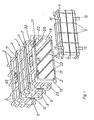
- the storage and transport container for ammunition shown in the drawing is designated as a whole by 1 and is made from an injection molded body, for example from a modified tough polyethylene, in the basic form of a flat cuboid with an open one End face 2 formed.
- the container 1 On its outer sides, the container 1 is provided with reinforcing ribs 3 which intersect each other and which are in one piece are formed with the container 1 and form a honeycomb grid on the surface thereof.
- the open end face 2 of the container 1 is assigned a container lid 4, which in turn is formed by an injection molded body, for example also made of modified tough polyethylene, and like the container 1 is provided on the outside with intersecting stiffening ribs 5.
- the edge regions thereof are also encompassed by the stiffening ribs 3 and 5, respectively.
- This configuration ensures that, in the case of a container 1 and / or cover 4, the actual container or cover wall is not immediately loaded, but first the stiffening ribs can absorb the forces that occur through deformation.
- the honeycomb surface structure of the container 1 is of receiving grooves 6 for reinforcing bandages 7 made of metal, e.g. Aluminum, interrupted, which are formed by webs 8 which are integrally formed on the surface of the container 1 in accordance with the stiffening ribs 3 and which run in the transverse direction around the outer circumference of the container 1.
- the container 1 already has a high degree of resilience due to the honeycomb grid of its stiffening ribs 3, the optionally provided reinforcing bandages 7 can be used to hold the stacking strips one above the other in a stack of containers 1 without any significant stress on the Container 1 itself is done.
- the reinforcing bandages 7 have a double-T profile and each encompass the container 1 in a U-shape, half from above and half from below, the two U-shaped bandages halves are firmly connected to each other at their joints 9, for example riveted together to form rivet chambers 10.
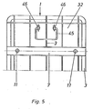
- the upper reinforcement bandages 7 can be provided with protruding stacking cams 11 and the lower reinforcement bandages 7 can be provided with corresponding openings (not shown) receiving the cams 11. This ensures reliable stack formation.
- the container lid 4 formed by the plastic molded body is provided on the inside with a reinforcing lid 12 made of metal, preferably V2A steel, as stiffening.
- a seal 14 is inserted, on which, in the state of the cover 4 closing the container 1 together with the inner cover 12, the end face edge 15 of the open end face 2 of the container 1 is pressed with sealing engagement.
- the reinforcement cover 12 made of metal is clipped into the plastic cover 4 using its elasticity.
- the lid 4 is closed by means of known quick-release fasteners 16 in the manner of so-called box fasteners, which are engaged and locked with corresponding counter-members 17 on the container side in order to close the container 1.
- the container 1 defines a receiving space for two storeys 18 to be stored in this storey, which comprises two guide chambers 19 and 20 arranged one above the other, each with a carrier pull-out 21, 22 receiving the storeys 18 in series.
- the carrier pull-outs 21 and 22 are made of a suitable plastic, and in order to reduce the frictional force, the lower carrier pull-out 21 slides on ribs 23, which on the inside of the container bottom 24 are integrally formed.
- the receiving space of the container 1 is provided on the inside with two profile rails 26 which are arranged along the two longitudinal walls 25 of the container in a common horizontal transverse plane, which extend in the pulling-out direction of the carrier pull-outs 21, 22 and are integrally formed with the container 1.
- the profiled strips 26 are shaped for the run-on bevel.
- the underside 27 forms an upper boundary of the lower guide chamber 19 and the upper side 28 forms a lower boundary of the upper guide chamber 20 and at the same time also a guide surface for the upper carrier pull-out 22 (FIG. 4).
- the groove-like cavity 29 formed on the outside by the shaping of the profiled strips 26 in the container longitudinal walls 25 is penetrated by the vertical stiffening ribs 3, which also form the honeycomb structure of the container surface.
- the upper guide chamber 20 is delimited on the upper side by webs 30 and 31 formed integrally with the container, which protrude from the top or upper wall 32 of the container 1 into the guide chamber 20 by a dimension corresponding to the respective diameter of the projectiles 18.
- the upper guide chamber 20 is further provided on its two longitudinal sides inside with integrally molded limiting webs 33 with the container longitudinal walls 25, which overlap the upper support pull-out 22 on the edge and in particular provide guidance for the support pull-out 22 emptied from the storeys 18, since in this case the the ammunition diameter, from the top wall 32 of the container 1 downward webs 30 and 31 no longer have a guiding effect.
- the carrier extensions 21 and 22 each consist of individual elements 34 which are articulated in the region of the lower edge of their adjoining end faces and which, according to the example shown, preferably receive two storeys 18 each in the correct shape and support them on the underside. Both carrier pull-outs 21 and 22 are provided in their bottom area with guide eyelets (not shown in more detail) for receiving two elastic belts 35, which are arranged at a distance on both sides of the vertical longitudinal center plane of the container 1 and serve to fix the carrier pull-outs 21, 22 in the container 1.
- the straps 35 are each attached to the underside of the individual element 34 adjacent to the open end face 2 of the container or the container lid 4 in the front end region thereof and from the underside of the lower carrier pull-out 21 to the underside of the upper carrier pull-out 22 with deflection at the opposite end of the container lid 4
- the end of the container is guided by a deflection roller 37 loosely inserted into the end wall 36 of the container.
- the two carrier pull-outs 21 and 22 form a unit which is connected to one another by the elastic belts 35 and which can be pushed as a whole into the container 1.
- the deflecting rollers 37 form holding points on the container side which prevent the carrier pull-outs 21, 22 from slipping out of the container 1 prevent.
- the container-side fixing of the carrier pull-outs 21 and 22 by means of the deflecting rollers 37 takes place when the carrier pull-out unit is pushed into the container 1 in that the respective belt 35 is pulled out of the container 1 through a slot-shaped opening 38 in the end wall 36, whereupon the deflecting roller 37 of outside through the opening 38 with the inclusion of a wrap area of the belt 35 in its bearing 39 is used, which is formed by suitable formations 40 of the end wall 36, in which the respective deflecting roller 37 engages with its two end regions freely rotatably and against which it is pressed by the belt 35 which is returned through the opening 38. From the outside, the wall openings 38 are then releasably closed with the aid of closure plates 41 with an inserted sealing ring, for example by screwing.
- each carrier pull-out 21, 22 can be pulled out of the container 1, with the pull-out of one carrier pull-out, the other carrier pull-out in each case through the elastic belts 35, which lengthen and roll on the deflection rollers 37 increasingly increasing tensile force is pulled into the container 1, so that normally not both carrier extensions 21,22 can be pulled out of their guide chambers 19,20 at the same time.
- the articulated connection of the individual elements 34 of the carrier pull-outs 21 and 22 makes it possible, after the projectiles 18 have been removed from the first and the subsequent individual elements 34, to fold the individual element downward, as a result of which freedom of space is maintained on the removal side of the container.
- the individual elements 34 are provided on their two end faces 42 with their bottom surface 43 extending bevels 44 of at least approximately 45 °, the hinge axis being in the region of the cutting line of the bevels 44 and the end faces 42.
- the emptied individual elements 34 can be pivoted downward by at least approximately 90 °. In this way, after removing the container lid 4, any carrier pull-out 21, 22 can be gripped and pulled out of the container 1 to the front be drawn.
- the projectiles 18, which can also be belted, are removed in the order in which the individual elements 34 appear, the respectively empty individual element 34 folding down. After emptying, the carrier extract in question slides back into its guide chamber, whereupon the other carrier extract can be released and pulled out for the removal of ammunition.
- U-shaped carrying handles 45 are provided, which are attached to the upper wall 32 of the container 1 with the aid of brackets 46 and can be pivoted between a folded-up use position and a folded-down rest position, in which they are undercut in a stiffening rib 3 locked and thus fixed in a position located below the outer rib plane, which does not affect the stacking of the container 1.
Landscapes
- Engineering & Computer Science (AREA)
- General Engineering & Computer Science (AREA)
- Packages (AREA)
- Rigid Containers With Two Or More Constituent Elements (AREA)
Applications Claiming Priority (2)
| Application Number | Priority Date | Filing Date | Title |
|---|---|---|---|
| DE19803033481 DE3033481C2 (de) | 1980-09-05 | 1980-09-05 | Lager- und Transportbehälter für insbesondere gegurtete Munition |
| DE3033481 | 1980-09-05 |
Publications (2)
| Publication Number | Publication Date |
|---|---|
| EP0047862A1 true EP0047862A1 (fr) | 1982-03-24 |
| EP0047862B1 EP0047862B1 (fr) | 1984-03-14 |
Family
ID=6111230
Family Applications (1)
| Application Number | Title | Priority Date | Filing Date |
|---|---|---|---|
| EP19810106273 Expired EP0047862B1 (fr) | 1980-09-05 | 1981-08-12 | Réceptacle pour le stockage et le transport de munitions |
Country Status (2)
| Country | Link |
|---|---|
| EP (1) | EP0047862B1 (fr) |
| DE (1) | DE3033481C2 (fr) |
Cited By (5)
| Publication number | Priority date | Publication date | Assignee | Title |
|---|---|---|---|---|
| EP2031344A1 (fr) * | 2007-08-31 | 2009-03-04 | Saab Ab | Caisse de transport supprimant l'explosion de poudre |
| WO2015028544A1 (fr) * | 2013-08-30 | 2015-03-05 | Plastpack Defence Aps | Contenant pour matériel explosif |
| WO2016138909A1 (fr) | 2015-03-04 | 2016-09-09 | Plastpack Defence Aps | Boîte de munitions légère |
| CN106885499A (zh) * | 2017-01-23 | 2017-06-23 | 北京北方长龙新材料技术有限公司 | 一种可单独拆装弹/药丸存储单元的框架式弹药箱 |
| CN110017740A (zh) * | 2019-04-25 | 2019-07-16 | 武汉雷神特种器材有限公司 | 一种具备发射装置的携行包装箱 |
Families Citing this family (3)
| Publication number | Priority date | Publication date | Assignee | Title |
|---|---|---|---|---|
| DE3619237A1 (de) * | 1986-06-07 | 1987-12-10 | Deutsche Verpackungsmittel | Munitionskiste |
| CN105352377A (zh) * | 2015-11-24 | 2016-02-24 | 张家港泰科力合安保科技有限公司 | 一种一体式可编程的子弹抽屉 |
| DE102024101079A1 (de) * | 2024-01-15 | 2025-07-17 | Rheinmetall Landsysteme Gmbh | Munitionsladekiste und system |
Citations (2)
| Publication number | Priority date | Publication date | Assignee | Title |
|---|---|---|---|---|
| AT249554B (de) * | 1963-12-16 | 1966-09-26 | Friedrich Stuebbe | Packkasten mit stirnseitigen Verschlußdeckeln für die Verpackung von mindestens zwei Geschoßfächern |
| DE2620930A1 (de) * | 1976-05-12 | 1977-11-24 | Kern & Grosskinsky | Magazin bzw. halterung fuer laengliche behaelter, insbesondere geschosskoerper und treibladungsbehaelter |
Family Cites Families (1)
| Publication number | Priority date | Publication date | Assignee | Title |
|---|---|---|---|---|
| NL254759A (fr) * | 1959-01-19 |
-
1980
- 1980-09-05 DE DE19803033481 patent/DE3033481C2/de not_active Expired
-
1981
- 1981-08-12 EP EP19810106273 patent/EP0047862B1/fr not_active Expired
Patent Citations (2)
| Publication number | Priority date | Publication date | Assignee | Title |
|---|---|---|---|---|
| AT249554B (de) * | 1963-12-16 | 1966-09-26 | Friedrich Stuebbe | Packkasten mit stirnseitigen Verschlußdeckeln für die Verpackung von mindestens zwei Geschoßfächern |
| DE2620930A1 (de) * | 1976-05-12 | 1977-11-24 | Kern & Grosskinsky | Magazin bzw. halterung fuer laengliche behaelter, insbesondere geschosskoerper und treibladungsbehaelter |
Cited By (11)
| Publication number | Priority date | Publication date | Assignee | Title |
|---|---|---|---|---|
| EP2031344A1 (fr) * | 2007-08-31 | 2009-03-04 | Saab Ab | Caisse de transport supprimant l'explosion de poudre |
| WO2015028544A1 (fr) * | 2013-08-30 | 2015-03-05 | Plastpack Defence Aps | Contenant pour matériel explosif |
| US10024640B2 (en) | 2013-08-30 | 2018-07-17 | Plastpack Defence Aps | Container for explosive material |
| WO2016138909A1 (fr) | 2015-03-04 | 2016-09-09 | Plastpack Defence Aps | Boîte de munitions légère |
| DK178731B1 (en) * | 2015-03-04 | 2016-12-12 | Plastpack Defence Aps | Lightweight ammunition box |
| JP2018508736A (ja) * | 2015-03-04 | 2018-03-29 | プラストパック ディフェンス エーピーエスPlastpack Defence Aps | 軽量の弾薬箱 |
| US10190859B2 (en) | 2015-03-04 | 2019-01-29 | Plastpack Defence Aps | Lightweight ammunition box |
| AU2018236832B2 (en) * | 2015-03-04 | 2020-07-09 | Plastpack Defence Aps | Lightweight Ammunition Box |
| CN106885499A (zh) * | 2017-01-23 | 2017-06-23 | 北京北方长龙新材料技术有限公司 | 一种可单独拆装弹/药丸存储单元的框架式弹药箱 |
| CN106885499B (zh) * | 2017-01-23 | 2018-07-03 | 北京北方长龙新材料技术有限公司 | 一种可单独拆装弹/药丸存储单元的框架式弹药箱 |
| CN110017740A (zh) * | 2019-04-25 | 2019-07-16 | 武汉雷神特种器材有限公司 | 一种具备发射装置的携行包装箱 |
Also Published As
| Publication number | Publication date |
|---|---|
| DE3033481C2 (de) | 1985-02-21 |
| EP0047862B1 (fr) | 1984-03-14 |
| DE3033481A1 (de) | 1982-03-25 |
Similar Documents
| Publication | Publication Date | Title |
|---|---|---|
| EP3759030B1 (fr) | Contenant de transport à séparation variable de compartiment | |
| EP0048006A1 (fr) | Casier divisible pour bouteilles | |
| DE3709190C2 (fr) | ||
| DE2643720C2 (de) | Stapelbarer Transportbehälter | |
| EP0524658B1 (fr) | Palette en matière plastique | |
| EP0047862B1 (fr) | Réceptacle pour le stockage et le transport de munitions | |
| DE2236426C3 (de) | Formschachtel zum Aufnehmen von zerbrechlichen Gütern | |
| DE2253736C3 (de) | Schaukarton für zerbrechliche Gegenstände, insbesondere Eier | |
| DE29805365U1 (de) | Mehrzweckkoffer | |
| DE2220274B2 (de) | Karton zum Verpacken von Eiern u.dgl | |
| EP3247648B1 (fr) | Contenant présentoir | |
| DE4228949C2 (de) | Transportkasten aus Kunststoff | |
| EP0236514B1 (fr) | Caisse de transport et de stockage en matière plastique | |
| DE9211696U1 (de) | Transportkasten aus Kunststoff | |
| DE29819420U1 (de) | Tablar o.dgl. Tragmittel | |
| EP0386313A1 (fr) | Moyen de transport et de stockage en matière plastique | |
| DE3004673C2 (fr) | ||
| DE9208481U1 (de) | Lager-und Transportbehälter | |
| DE2902689A1 (de) | Behaelter fuer den transport gefaehrlicher fluessigkeiten | |
| DE1902533A1 (de) | Entnahmevorrichtung fuer Materialkaesten | |
| DE2954497C2 (de) | Stapelbarer Transport- und Lagersichtkasten aus Kunststoff | |
| EP0615912A1 (fr) | Récipient de transport et d'emballage | |
| DE4333626C2 (de) | Transportkasten aus Kunststoff | |
| DE102020102543A1 (de) | Lagersystem für Kleinteile | |
| DE1172602B (de) | Behaelter zum Aufbewahren von Dia-Magazinen |
Legal Events
| Date | Code | Title | Description |
|---|---|---|---|
| PUAI | Public reference made under article 153(3) epc to a published international application that has entered the european phase |
Free format text: ORIGINAL CODE: 0009012 |
|
| AK | Designated contracting states |
Designated state(s): CH FR GB IT |
|
| 17P | Request for examination filed |
Effective date: 19820318 |
|
| ITF | It: translation for a ep patent filed | ||
| GRAA | (expected) grant |
Free format text: ORIGINAL CODE: 0009210 |
|
| AK | Designated contracting states |
Designated state(s): CH FR GB IT LI |
|
| ET | Fr: translation filed | ||
| PLBI | Opposition filed |
Free format text: ORIGINAL CODE: 0009260 |
|
| 26 | Opposition filed |
Opponent name: HOFFMANN-WERKE J. OSWALD HOFFMANN GMBH Effective date: 19841205 |
|
| PLBN | Opposition rejected |
Free format text: ORIGINAL CODE: 0009273 |
|
| STAA | Information on the status of an ep patent application or granted ep patent |
Free format text: STATUS: OPPOSITION REJECTED |
|
| 27O | Opposition rejected |
Effective date: 19861211 |
|
| ITTA | It: last paid annual fee | ||
| PGFP | Annual fee paid to national office [announced via postgrant information from national office to epo] |
Ref country code: GB Payment date: 19920806 Year of fee payment: 12 |
|
| PGFP | Annual fee paid to national office [announced via postgrant information from national office to epo] |
Ref country code: FR Payment date: 19920827 Year of fee payment: 12 |
|
| PGFP | Annual fee paid to national office [announced via postgrant information from national office to epo] |
Ref country code: CH Payment date: 19920902 Year of fee payment: 12 |
|
| PG25 | Lapsed in a contracting state [announced via postgrant information from national office to epo] |
Ref country code: GB Effective date: 19930812 |
|
| PG25 | Lapsed in a contracting state [announced via postgrant information from national office to epo] |
Ref country code: LI Effective date: 19930831 Ref country code: CH Effective date: 19930831 |
|
| GBPC | Gb: european patent ceased through non-payment of renewal fee |
Effective date: 19930812 |
|
| PG25 | Lapsed in a contracting state [announced via postgrant information from national office to epo] |
Ref country code: FR Effective date: 19940429 |
|
| REG | Reference to a national code |
Ref country code: CH Ref legal event code: PL |
|
| REG | Reference to a national code |
Ref country code: FR Ref legal event code: ST |
|
| PLAB | Opposition data, opponent's data or that of the opponent's representative modified |
Free format text: ORIGINAL CODE: 0009299OPPO |