EP0048019B1 - Dispositif de sécurité pour des outils à main ou des outils - Google Patents
Dispositif de sécurité pour des outils à main ou des outils Download PDFInfo
- Publication number
- EP0048019B1 EP0048019B1 EP81107265A EP81107265A EP0048019B1 EP 0048019 B1 EP0048019 B1 EP 0048019B1 EP 81107265 A EP81107265 A EP 81107265A EP 81107265 A EP81107265 A EP 81107265A EP 0048019 B1 EP0048019 B1 EP 0048019B1
- Authority
- EP
- European Patent Office
- Prior art keywords
- handle
- switch
- implement
- power tool
- container
- Prior art date
- Legal status (The legal status is an assumption and is not a legal conclusion. Google has not performed a legal analysis and makes no representation as to the accuracy of the status listed.)
- Expired
Links
- 239000012530 fluid Substances 0.000 claims description 8
- 210000004712 air sac Anatomy 0.000 description 13
- 230000000994 depressogenic effect Effects 0.000 description 3
- 208000027418 Wounds and injury Diseases 0.000 description 2
- 230000006378 damage Effects 0.000 description 2
- 208000014674 injury Diseases 0.000 description 2
- 230000035939 shock Effects 0.000 description 2
- 239000004020 conductor Substances 0.000 description 1
- 238000010586 diagram Methods 0.000 description 1
- 239000012777 electrically insulating material Substances 0.000 description 1
- 239000000463 material Substances 0.000 description 1
- 239000004033 plastic Substances 0.000 description 1
- 229920003023 plastic Polymers 0.000 description 1
- 238000004804 winding Methods 0.000 description 1
Images

Classifications
-
- F—MECHANICAL ENGINEERING; LIGHTING; HEATING; WEAPONS; BLASTING
- F16—ENGINEERING ELEMENTS AND UNITS; GENERAL MEASURES FOR PRODUCING AND MAINTAINING EFFECTIVE FUNCTIONING OF MACHINES OR INSTALLATIONS; THERMAL INSULATION IN GENERAL
- F16P—SAFETY DEVICES IN GENERAL; SAFETY DEVICES FOR PRESSES
- F16P3/00—Safety devices acting in conjunction with the control or operation of a machine; Control arrangements requiring the simultaneous use of two or more parts of the body
- F16P3/18—Control arrangements requiring the use of both hands
- F16P3/20—Control arrangements requiring the use of both hands for electric control systems
-
- A—HUMAN NECESSITIES
- A01—AGRICULTURE; FORESTRY; ANIMAL HUSBANDRY; HUNTING; TRAPPING; FISHING
- A01D—HARVESTING; MOWING
- A01D34/00—Mowers; Mowing apparatus of harvesters
- A01D34/01—Mowers; Mowing apparatus of harvesters characterised by features relating to the type of cutting apparatus
- A01D34/412—Mowers; Mowing apparatus of harvesters characterised by features relating to the type of cutting apparatus having rotating cutters
- A01D34/63—Mowers; Mowing apparatus of harvesters characterised by features relating to the type of cutting apparatus having rotating cutters having cutters rotating about a vertical axis
- A01D34/82—Other details
- A01D34/828—Safety devices
-
- B—PERFORMING OPERATIONS; TRANSPORTING
- B27—WORKING OR PRESERVING WOOD OR SIMILAR MATERIAL; NAILING OR STAPLING MACHINES IN GENERAL
- B27B—SAWS FOR WOOD OR SIMILAR MATERIAL; COMPONENTS OR ACCESSORIES THEREFOR
- B27B17/00—Chain saws; Equipment therefor
- B27B17/08—Drives or gearings; Devices for swivelling or tilting the chain saw
- B27B17/083—Devices for arresting movement of the saw chain
-
- A—HUMAN NECESSITIES
- A01—AGRICULTURE; FORESTRY; ANIMAL HUSBANDRY; HUNTING; TRAPPING; FISHING
- A01D—HARVESTING; MOWING
- A01D2101/00—Lawn-mowers
-
- H—ELECTRICITY
- H01—ELECTRIC ELEMENTS
- H01H—ELECTRIC SWITCHES; RELAYS; SELECTORS; EMERGENCY PROTECTIVE DEVICES
- H01H2225/00—Switch site location
- H01H2225/008—Two different sites for one circuit, e.g. for safety
-
- H—ELECTRICITY
- H01—ELECTRIC ELEMENTS
- H01H—ELECTRIC SWITCHES; RELAYS; SELECTORS; EMERGENCY PROTECTIVE DEVICES
- H01H3/00—Mechanisms for operating contacts
- H01H3/22—Power arrangements internal to the switch for operating the driving mechanism
- H01H3/24—Power arrangements internal to the switch for operating the driving mechanism using pneumatic or hydraulic actuator
-
- H—ELECTRICITY
- H01—ELECTRIC ELEMENTS
- H01H—ELECTRIC SWITCHES; RELAYS; SELECTORS; EMERGENCY PROTECTIVE DEVICES
- H01H9/00—Details of switching devices, not covered by groups H01H1/00 - H01H7/00
- H01H9/02—Bases, casings, or covers
- H01H9/06—Casing of switch constituted by a handle serving a purpose other than the actuation of the switch, e.g. by the handle of a vacuum cleaner
Definitions
- powered tools and implements covers hand-held power tools, for example hedge trimmers, chain saws and angle grinders and the like, as well as implements which are not hand-held but whose operation is controlled by the hands of a user.
- Such implements include lawn mowers, scarifiers and cultivators.
- Hedge trimmers, chain saws and angle grinders are usually provided with the two handles to enable the user to control the tool more easily.
- the user will sometimes hold and operate the tool with one hand only and thereby expose himself to the risk of injury either to the hand not holding the tool or to another part of his body because he has insufficient control over the tool.
- a hedge trimmer For example electrically-powered hedge trimmers are fitted with two series-connected control switches both of which have to be actuated before the tool is energised.
- one switch is built into the main handle of the trimmer and is usually in the form of a trigger-operated switch and will be referred to as a primary switch.
- Another switch to be referred to as a secondary switch is connected in series with the primary switch and is associated with the other handle of the hedge trimmer in such manner that the secondary switch can be operated only when the user grasps the other handle.
- the hedge trimmer will be energised only when both switches are operated and this occurs only when the user grasps the main handle with one hand and the secondary handle with his other hand. Removal of either hand from the respective handle will release the appropriate switch and the tool is de-energised.
- a power tool or implement comprising an electric motor, a primary switch and a secondary switch so arranged that said electric motor can be actuated only when both said switches are actuated, characterized in that said secondary switch is actuable by fluid under pressure, and further characterized in that said power tool or implement further comprises a container manually deformable to provide fluid under pressure, and means for transmitting fluid under pressure from said container to said secondary switch.
- the power tool or implement includes a single handle upon which said container is mounted, and means for actuating said primary switch mounted on said handle remote from said container to inhibit simultaneous actuation of said primary switch and deformation of said container with the same hand.
- the power tool or implement includes a primary handle provided with means for actuating said primary switch, and a secondary handle upon which said container is mounted.
- the container is accommodated within its handle.
- such an embodiment includes a user actuable member mounted on said handle and movable relative thereto to deform said container.
- the container is of elongate form and said user actuable member is substantially co-extensive therewith.
- the user actuable member protrudes beyond said handle and said handle is provided with inturned lips which retain said user actuable member in said handle.
- the power tool or implement includes delay means for preventing energisation of said electric motor if actuation of said primary switch and deformation of said container do not occur within a predetermined time.
- delay means comprises a time delay operatively connected to both said primary switch and said secondary switch so as to be set in operation when either said primary switch or said secondary switch is actuated and which time delay is rendered inoperative in the event that deformation of the other of said primary switch and said secondary switch follows within a predetermined time.
- the time delay is connected to a switch which is actuated by said time delay to prevent actuation of said electric motor in the event that said primary switch and said secondary switch are not actuated within said predetermined time.
- said fluid is air.
- Fig. 1 shows a hedge trimmer in perspective view.
- the trimmer includes a body 1 housing an electric motor and a drive mechanism for cutter members 2, 3 that extend forwardly from the body 1. Extending rearwardly from the body 1 is a main handle handle 4 with a trigger 5 for operating an electric switch housed within the main handle.
- a releasable "lock-off" button 6 projects sideways from the handle. Button 6 must be depressed before actuation of the trigger 5.
- a secondary handle 7 Fixed to the forward side of the body 1 is a secondary handle 7 of inverted U-shaped form.
- the vertical limbs of the U are inturned as at 8 to contact the side walls of the body 1.
- the handle 7 is secured to the body 1 by screws one of which is shown at 9 and which pass through the inturned portions 8 and into the body 1.
- a forward guard 10 with a horizontal part 11 secured to the underside of the body 1 has a vertical part 12 interposed between the secondary handle 7 and the adjacent ends of the cutter members 2, 3.
- the cutter members 2, 3 are arranged one above the other, the lower member 3 being fixed in the body 1 while the upper member 2 extends into the body and is connected to a mechanism which converts the rotary motion of the rotor of the electric driving motor to a reciprocatory motion for reciprocating the upper member 2 relatively to the lower member 3.
- Both members 2, 3 have laterally extending teeth 13 and they operate in the conventional manner to cut hedges, trim bushes and the like. It us, of course, possible to drive both cutter members.
- the secondary handle 7 is of channel form over most of its length, the channel accommodating an elongate, flexible-walled air sac 14 closed at one end and joined at the other end to a length of connector tube described in more detail below.
- the air sac 14 is indicated in Fig. 1 by the dotted line and as can be seen from that Figure the tube is co-extensive with the U-shaped part of the secondary handle 7.
- the channel in the handle 7 has inturned lips 15 which retain an actuator member 16 also of generally U-shaped form as can be seen from Fig. 1 and having grooves 17 in its side walls which coact with the lips 15 to retain the actuator member in the channel in handle 7.
- the outer face 18 of the actuator member is gently rounded as indicated in Fig. 2 to form a head, the body of the actuator being movable into the channel in the handle as will be described below.
- the air sac 14 is shown in more detail in Fig. 3 and, as has been described above, the sac is closed at one end as at 19 and connected at the other to a connector tube 20 which is housed in one of the inturned portions 8 of the handle 7.
- the end wall 21 (Fig. 4) of the inturned part 8 housing the connector tube 20 is formed with a nozzle 22 over which the end of the connector tube 20 fits as can be seen in Fig. 4.
- Extending into the bore of the nozzle 22 is a hollow pin 23 that is a force fit in an aperture 24 in the wall 25 of the body 1.
- the pin 23 extends into the body 1 and is connected to a pneumatically-operated electric switch - the secondary switch - located inside the body 1 via a connecting tube 26.
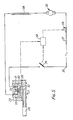
- FIG. 5 A typical pneumatically-operated switch is shown in Fig. 5. Clamped between a base plate 27 and an inverted cup-shaped housing 28 is a flexible diaphragm 29 that supports a cup 30 movable within the housing 28 against the action of a helical spring 31. Fixed to the base of the cup 30 is a shorting bar 32 which, with fixed contacts 33, 34 forms the secondary switch referred to above. The contacts 33, 34 are mounted in but insulated from the housing 28.
- the fixed contacts 33, 34 are in series electrical connection with a primary switch 35 actuated by the trigger 5, supply terminals 36, 37, the field winding 38 and the brushes and commutator 39 of the electric motor housed within the body 1.
- the input terminals 36, 37 are connected to the conductors of a supply cable 40 that extends from the main handle 4 as can be seen from Fig. 1.
- a user grasps the main handle 4 in one hand and the secondary handle 7 in the other.
- the trigger 5 is actuated so closing switch 35, the "lock-off" button 6 having been depressed to allow the trigger 5 to be actuated.
- the actuator member 16 is depressed thereby compressing part at least of the air sac 14 and increasing the air pressure therein to a value such that the diaphragm 29 is flexed upwardly so moving cup 30 upwardly (as seen in Fig. 5) causing the shorting bar 32 to bridge the fixed contacts 33, 34 and thereby complete the energising circuit of the driving motor.
- the motor will be de-energised because either the primary switch 35 will open or the secondary switch will open.
- the air sac 14 and the connecting tubes 20 and 26 are made of an electrically-insulating material, for example a plastics or rubber material and thereby isolate the user from the secondary switch. Only a light spring loading of the diaphragm is required thereby requiring only a little pressure to compress the air sac 14 to operate the secondary switch and in this manner user fatique is prevented.
- the secondary switch is operated pneumatically and the connecting tubes are flexible, the switch can readily be located in a position where it can easily be protected against ingress of moisture.
- the secondary switch is located in the body 1 which is "splash-proofed" or protected against the ingress of moisture.
- the pneumatic system is also of the "fail-safe" type because if a leak develops in the air sac or elsewhere in the pneumatic circuit, the secondary switch cannot be operated.
- the user will always operate the secondary switch irrespective of the exact point at which he grasps the handle.
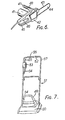
- Fig. 6 is a perspective view of a chain saw embodying the invention. Except as described below, the chain saw is of conventional form having a housing 41 accommodating an electric driving motor whose output shaft drives, via gearing contained in a gear case 42 joined to the housing 41, a cutter chain 43 supported in conventional manner on a cutter bar 44. Extending rearwardly from the gear case 42 is main handle 45 with a trigger 46 that actuates a primary switch (not shown) housed in the handle 45.
- actuator member 48 Projecting from the gear case 42 in a secondary handle 47 in whose upper surface is located an actuator member 48 of similar design to actuator member 16 described above.
- Member 48 is located un a channel in the handle 47 and the channel also houses an elongate air sac (not shown) joined by a connecting tube (not shown) to a diaphragm-operated switch (not shown) similar to that described above with reference to Fig. 5 and located in the motor housing 41.
- the diaphragm operated switch is the secondary switch and is series connected with the primary switch actuated by trigger 46.
- the actuator member 48 is, as can be seen from Fig. 6, co-extensive with the handle 47 and is, therefore, operated by the user regardless of the precise position of the user's hand on the handle.
- Fig. 7 is a perspective view of a lawn mower embodying the invention.
- the mower shown is of the air cushion supported type but it could be a cylinder mower or a rotary mower.
- Housing 49 accommodates the mower driving motor and is mounted upon a cutter cover 50 that accommodates the impeller and cutter bar of the mower, these latter components being driven by the motor.
- a handle 51 Extending from the cover 50 is a handle 51 by which a user guides the mower over a grassed surface.
- a housing 53 Mounted on the handle 51 adjacent a horizontal portion 52 thereto is a housing 53 incorporating an electric switch - the primary switch - that controls the application of electric power to the motor via a connecting cable 54.
- the primary switch is operated by a lever 55.
- an actuator member 56 similar to member 16 described above.
- the end of member 56 is spaced from the lever 55 by a distance sufficient to prevent a user operating both the lever 55 and the actuator member 56 by the same hand.
- the actuating member 56 may extend for a short distance down the vertical limb of the handle as indicated at 57.
- an elongate resilient air sac similar to sac 14 described above.
- the air sac is joined by a connector tube located within the handle to a secondary switch located in the housing 53 and in series connection with the primary switch with that housing.
- the safety arrangement according to the invention may be supplemented by a unit for controlling the flow of energy to the motor only if both switches are operated within a particular time, for example within fifteen seconds.
- the unit may be an electronic circuit incorporating a timer actuated when either the primary or secondary switch is closed and de-actuated when the secondary or primary switch is closed. Unless de-activated, the time will "time-out" after fifteen seconds and open the motor energising circuit.
- the unit is energised from the supply terminals and is shown schematically in dotted lines in Fig. 5.
- the circuit incorporating the timer is shown as rectangle 58 with inputs from primary switch 35 and the secondary switch and an output controlling the operation of a switch 59.
- a user may actuate the primary switch 35 before he compresses the air sac, or he may carry out both operations substantially simultaneously, or he may compress the air sac before he actuates the primary switch.
- the timer is actuated when the first component is operated and deactivated when the second component is actuated provided the latter takes place within the fifteen seconds. In the second case, the timer is not activated.
- switch 59 remains open.
Landscapes
- Life Sciences & Earth Sciences (AREA)
- Engineering & Computer Science (AREA)
- General Engineering & Computer Science (AREA)
- Mechanical Engineering (AREA)
- Environmental Sciences (AREA)
- Wood Science & Technology (AREA)
- Forests & Forestry (AREA)
- Harvester Elements (AREA)
- Portable Nailing Machines And Staplers (AREA)
- Scissors And Nippers (AREA)
- Finish Polishing, Edge Sharpening, And Grinding By Specific Grinding Devices (AREA)
Claims (11)
Priority Applications (1)
| Application Number | Priority Date | Filing Date | Title |
|---|---|---|---|
| AT81107265T ATE16847T1 (de) | 1980-09-15 | 1981-09-15 | Sicherheitseinrichtung fuer handmaschinen oder werkzeuge. |
Applications Claiming Priority (2)
| Application Number | Priority Date | Filing Date | Title |
|---|---|---|---|
| GB8029763 | 1980-09-15 | ||
| GB8029763 | 1980-09-15 |
Publications (3)
| Publication Number | Publication Date |
|---|---|
| EP0048019A2 EP0048019A2 (fr) | 1982-03-24 |
| EP0048019A3 EP0048019A3 (en) | 1983-01-12 |
| EP0048019B1 true EP0048019B1 (fr) | 1985-12-04 |
Family
ID=10516086
Family Applications (1)
| Application Number | Title | Priority Date | Filing Date |
|---|---|---|---|
| EP81107265A Expired EP0048019B1 (fr) | 1980-09-15 | 1981-09-15 | Dispositif de sécurité pour des outils à main ou des outils |
Country Status (4)
| Country | Link |
|---|---|
| US (1) | US4449062A (fr) |
| EP (1) | EP0048019B1 (fr) |
| AT (1) | ATE16847T1 (fr) |
| DE (1) | DE3173142D1 (fr) |
Families Citing this family (29)
| Publication number | Priority date | Publication date | Assignee | Title |
|---|---|---|---|---|
| DE3216446A1 (de) * | 1982-05-03 | 1983-11-03 | Fa. Andreas Stihl, 7050 Waiblingen | Sicherheitseinrichtung an einem tragbaren, motorisch angetriebenen handgeraet |
| DE3337146A1 (de) * | 1983-10-12 | 1985-04-25 | Icomag Trust Reg., Vaduz | Sicherheitsschalteinrichtung fuer elektrisch betriebene geraete, insbesondere fuer haushalt, werkstatt, garten o.dgl. |
| EP0267973B1 (fr) * | 1986-11-11 | 1992-02-12 | Black & Decker Inc. | Scie motorisée, en particulier scie entraînée par un moteur électrique |
| US4890007A (en) * | 1988-11-04 | 1989-12-26 | Vu Thuan D | Carpet mat switch |
| DE3929441C2 (de) * | 1989-09-05 | 1998-09-10 | Stihl Maschf Andreas | Handgeführtes Arbeitsgerät |
| US5150523A (en) * | 1991-07-11 | 1992-09-29 | Ryobi Motor Products Corporation | Deadman switch arrangement for a hedge trimmer |
| USD351096S (en) | 1992-04-06 | 1994-10-04 | Black & Decker Inc. | Hedge trimmer |
| DE9308698U1 (de) * | 1993-06-11 | 1994-10-27 | Dolmar GmbH, 22045 Hamburg | Handarbeitsgerät mit einem Antrieb |
| US5638945A (en) * | 1996-06-10 | 1997-06-17 | Ryobi North America, Inc. | Locking trigger mechanism for a portable power tool |
| JP3825136B2 (ja) * | 1997-05-14 | 2006-09-20 | 株式会社共立 | 手持ち式動力作業機 |
| JP3851717B2 (ja) * | 1997-10-17 | 2006-11-29 | 松下電器産業株式会社 | メンテナンス用副操作盤 |
| US6263979B1 (en) | 1998-07-24 | 2001-07-24 | The Black & Decker Corporation | Interchangeable implement system for power tools |
| US6249979B1 (en) * | 1998-08-13 | 2001-06-26 | Milwaukee Electric Tool Corporation | Orbital reciprocating saw |
| US6057518A (en) * | 1998-08-14 | 2000-05-02 | Black & Decker, Inc. | Lockout mechanism for power tool |
| US7836968B2 (en) * | 2006-03-24 | 2010-11-23 | The Stanley Works | Power tool with improved start actuator |
| US8008812B2 (en) | 2006-07-14 | 2011-08-30 | Aurora Office Equipment Co., Ltd. | Paper shredder control system responsive to touch-sensitive element |
| CN2915259Y (zh) | 2006-07-14 | 2007-06-27 | 上海震旦办公设备有限公司 | 碎纸机触碰安全装置 |
| CN201239643Y (zh) | 2008-08-06 | 2009-05-20 | 上海震旦办公设备有限公司 | 不择纸的全自动碎纸机 |
| CN201244502Y (zh) | 2008-08-19 | 2009-05-27 | 上海震旦办公设备有限公司 | 自动碎纸机可剃钉结构 |
| CN101543800A (zh) | 2009-05-07 | 2009-09-30 | 上海震旦办公设备有限公司 | 碎纸机防卡纸保护装置 |
| US8274004B2 (en) * | 2009-06-04 | 2012-09-25 | Selzer Donald F | Safety system and handle member therefor |
| JP5652241B2 (ja) * | 2011-02-18 | 2015-01-14 | 日立工機株式会社 | 携帯用作業機 |
| US8723468B2 (en) | 2011-04-28 | 2014-05-13 | Aurora Office Equipment Co., Ltd. | Cooled motor |
| JP5828384B2 (ja) * | 2011-08-03 | 2015-12-02 | 株式会社大成モナック | 背負式ヘッジトリマー |
| US8708260B2 (en) | 2011-08-08 | 2014-04-29 | Aurora Office Equipment Co., Ltd. | Depowered standby paper shredder and method |
| US10014128B2 (en) * | 2013-12-17 | 2018-07-03 | Robert Bosch Tool Corporation | Portable power tool with trigger switch, trigger release and lock-on mechanism combination |
| EP3031315B1 (fr) * | 2014-12-09 | 2021-09-01 | Robert Bosch GmbH | Dispositif de poignée pour outils de jardinage |
| JP6556536B2 (ja) | 2015-07-13 | 2019-08-07 | 株式会社マキタ | チェーンソー |
| JP7278169B2 (ja) * | 2019-08-07 | 2023-05-19 | 株式会社マキタ | 打撃工具 |
Family Cites Families (22)
| Publication number | Priority date | Publication date | Assignee | Title |
|---|---|---|---|---|
| US2366014A (en) * | 1941-12-16 | 1944-12-26 | Gen Electric | Safety switching arrangement for electrically heated appliances |
| CH373518A (de) * | 1959-11-07 | 1963-11-30 | Dent Bohren Hans Dr Med | Zahnbohrmaschine |
| US3268673A (en) * | 1963-05-09 | 1966-08-23 | Itt | Hydraulic pushbutton assembly |
| DE1295914B (de) * | 1964-05-19 | 1969-05-22 | Licentia Gmbh | Elektromotorisch angetriebene Heckenschere |
| US3459954A (en) * | 1965-04-10 | 1969-08-05 | Ero Sgorbani | Device for interrupting the flow of electrical current in motor vehicles |
| DE1507021C3 (de) * | 1965-07-05 | 1980-02-21 | Wolf-Geraete Gmbh, 5240 Betzdorf | Elektromotorisch angetriebene Heckenschere |
| FR1538909A (fr) * | 1967-09-28 | 1968-09-06 | Metabowerke Kg | Cisaille pour tailler les haies |
| DE6805182U (de) * | 1968-11-02 | 1969-03-06 | Closs Rauch & Schnitzler Kg | Heckenschere mit elektrischem antrieb |
| US3811284A (en) * | 1972-07-06 | 1974-05-21 | D Trussell | Control system |
| US3746938A (en) * | 1972-08-31 | 1973-07-17 | Tappan Co | Interlock circuit |
| US4205236A (en) * | 1975-03-20 | 1980-05-27 | Goof Sven Karl Lennart | Finger operated control system for hand-held appliances |
| US4003190A (en) * | 1975-08-07 | 1977-01-18 | Briggs & Stratton Corporation | Safety device for walk-behind rotary mowers |
| DE2617460A1 (de) * | 1976-04-21 | 1977-11-10 | Wolf Geraete Gmbh | Gartengeraet mit elektrisch angetriebenen werkzeugen |
| GB1541684A (en) * | 1976-04-27 | 1979-03-07 | Haigh Eng Co Ltd | Actuator assembly for an electric switch |
| DE2626201A1 (de) * | 1976-06-11 | 1977-12-22 | Stahlschmidt Kg | Sicherheits-bedienungsvorrichtung, insbesondere fuer elektromotorisch angetriebene rasenmaeher |
| US4105899A (en) * | 1977-01-12 | 1978-08-08 | Velosa Joseph M | Safety mat switch for machine tools and their like |
| US4161639A (en) * | 1977-07-01 | 1979-07-17 | Mtd Products Inc. | Handle safety switch |
| DE2839002A1 (de) * | 1978-09-07 | 1980-03-20 | Licentia Gmbh | Elektromotorisch angetriebene heckenschere |
| US4243970A (en) * | 1979-04-06 | 1981-01-06 | Hardee Patrick C | Open circuit alarm |
| US4266221A (en) * | 1979-09-20 | 1981-05-05 | Hawkins J C | Personnel alarm circuit for industrial machinery |
| DE3022852A1 (de) * | 1980-06-19 | 1982-01-07 | Metabowerke GmbH & Co, 7440 Nürtingen | Elektromotorisch angetriebenes handwerkzeug |
| DE3023033C2 (de) * | 1980-06-20 | 1987-03-26 | Metabowerke GmbH & Co, 7440 Nürtingen | Elektromotorisch angetriebenes Handwerkzeug |
-
1981
- 1981-09-15 DE DE8181107265T patent/DE3173142D1/de not_active Expired
- 1981-09-15 EP EP81107265A patent/EP0048019B1/fr not_active Expired
- 1981-09-15 US US06/302,699 patent/US4449062A/en not_active Expired - Lifetime
- 1981-09-15 AT AT81107265T patent/ATE16847T1/de not_active IP Right Cessation
Also Published As
| Publication number | Publication date |
|---|---|
| EP0048019A2 (fr) | 1982-03-24 |
| DE3173142D1 (en) | 1986-01-16 |
| EP0048019A3 (en) | 1983-01-12 |
| US4449062A (en) | 1984-05-15 |
| ATE16847T1 (de) | 1985-12-15 |
Similar Documents
| Publication | Publication Date | Title |
|---|---|---|
| EP0048019B1 (fr) | Dispositif de sécurité pour des outils à main ou des outils | |
| EP1836029B1 (fr) | Rasoirs | |
| EP2878191B1 (fr) | Outil motorisé à mouvement alternatif | |
| US4044532A (en) | Two-motion switch for cordless lawnmower | |
| EP2513941B1 (fr) | Outil électrique portatif comportant un dispositif d'indication d'activation | |
| EP0444909A2 (fr) | Outil à main motorisé avec un outil entraîné en rotation | |
| US5101567A (en) | Chain saw electric all-stop safety switch | |
| PL2243603T3 (pl) | Zespół maszynki do golenia na mokro i elektrycznego trymera | |
| US4528488A (en) | Warning device using power tool residual kinetic energy | |
| WO1999065633A8 (fr) | Scie a mouvement de va-et-vient animee par une perceuse | |
| US5223770A (en) | Portable handheld work apparatus having an electric drive motor | |
| EP0469757B1 (fr) | Outil motorisé | |
| EP1131994B1 (fr) | Coupeuse de végétation | |
| US6230598B1 (en) | Automatic cutting device | |
| US4559661A (en) | Paint scraper | |
| CN110125882B (zh) | 用于电驱动式园林工具的开关装置 | |
| JP3230936B2 (ja) | 手持ち式電動作業機 | |
| GB2139329A (en) | Improvements in or relating to hand-controlled electrically-powered appliances | |
| EP0692627A1 (fr) | Système de commande pour demarreur | |
| CN118716037A (zh) | 绿篱修剪机 | |
| CN116686528B (zh) | 工具机开关装置 | |
| KR100812711B1 (ko) | 유압식 전동가위장치 | |
| US4857681A (en) | Dead man-type electrical control device for power tools | |
| KR20090096013A (ko) | 휴대용 전동 전지가위 | |
| CN211671498U (zh) | 作业机械 |
Legal Events
| Date | Code | Title | Description |
|---|---|---|---|
| PUAI | Public reference made under article 153(3) epc to a published international application that has entered the european phase |
Free format text: ORIGINAL CODE: 0009012 |
|
| AK | Designated contracting states |
Designated state(s): AT BE CH DE FR GB IT LI LU NL SE |
|
| PUAL | Search report despatched |
Free format text: ORIGINAL CODE: 0009013 |
|
| AK | Designated contracting states |
Designated state(s): AT BE CH DE FR GB IT LI LU NL SE |
|
| 17P | Request for examination filed |
Effective date: 19830309 |
|
| GRAA | (expected) grant |
Free format text: ORIGINAL CODE: 0009210 |
|
| AK | Designated contracting states |
Designated state(s): AT BE CH DE FR GB IT LI LU NL SE |
|
| PG25 | Lapsed in a contracting state [announced via postgrant information from national office to epo] |
Ref country code: NL Effective date: 19851204 Ref country code: LI Effective date: 19851204 Ref country code: IT Free format text: LAPSE BECAUSE OF FAILURE TO SUBMIT A TRANSLATION OF THE DESCRIPTION OR TO PAY THE FEE WITHIN THE PRESCRIBED TIME-LIMIT;WARNING: LAPSES OF ITALIAN PATENTS WITH EFFECTIVE DATE BEFORE 2007 MAY HAVE OCCURRED AT ANY TIME BEFORE 2007. THE CORRECT EFFECTIVE DATE MAY BE DIFFERENT FROM THE ONE RECORDED. Effective date: 19851204 Ref country code: CH Effective date: 19851204 Ref country code: BE Effective date: 19851204 Ref country code: AT Effective date: 19851204 |
|
| REF | Corresponds to: |
Ref document number: 16847 Country of ref document: AT Date of ref document: 19851215 Kind code of ref document: T |
|
| REF | Corresponds to: |
Ref document number: 3173142 Country of ref document: DE Date of ref document: 19860116 |
|
| ET | Fr: translation filed | ||
| PG25 | Lapsed in a contracting state [announced via postgrant information from national office to epo] |
Ref country code: SE Effective date: 19860131 |
|
| REG | Reference to a national code |
Ref country code: CH Ref legal event code: PL |
|
| NLV1 | Nl: lapsed or annulled due to failure to fulfill the requirements of art. 29p and 29m of the patents act | ||
| PG25 | Lapsed in a contracting state [announced via postgrant information from national office to epo] |
Ref country code: LU Free format text: LAPSE BECAUSE OF NON-PAYMENT OF DUE FEES Effective date: 19860930 |
|
| PLBE | No opposition filed within time limit |
Free format text: ORIGINAL CODE: 0009261 |
|
| STAA | Information on the status of an ep patent application or granted ep patent |
Free format text: STATUS: NO OPPOSITION FILED WITHIN TIME LIMIT |
|
| 26N | No opposition filed | ||
| PGFP | Annual fee paid to national office [announced via postgrant information from national office to epo] |
Ref country code: FR Payment date: 19970820 Year of fee payment: 17 |
|
| PGFP | Annual fee paid to national office [announced via postgrant information from national office to epo] |
Ref country code: GB Payment date: 19970822 Year of fee payment: 17 Ref country code: DE Payment date: 19970822 Year of fee payment: 17 |
|
| PG25 | Lapsed in a contracting state [announced via postgrant information from national office to epo] |
Ref country code: GB Free format text: LAPSE BECAUSE OF NON-PAYMENT OF DUE FEES Effective date: 19980915 |
|
| GBPC | Gb: european patent ceased through non-payment of renewal fee |
Effective date: 19980915 |
|
| PG25 | Lapsed in a contracting state [announced via postgrant information from national office to epo] |
Ref country code: FR Free format text: LAPSE BECAUSE OF NON-PAYMENT OF DUE FEES Effective date: 19990531 |
|
| PG25 | Lapsed in a contracting state [announced via postgrant information from national office to epo] |
Ref country code: DE Free format text: LAPSE BECAUSE OF NON-PAYMENT OF DUE FEES Effective date: 19990701 |
|
| REG | Reference to a national code |
Ref country code: FR Ref legal event code: ST |