EP0048027A2 - Turbo-compound-Brennkraftmaschine - Google Patents
Turbo-compound-Brennkraftmaschine Download PDFInfo
- Publication number
- EP0048027A2 EP0048027A2 EP81107329A EP81107329A EP0048027A2 EP 0048027 A2 EP0048027 A2 EP 0048027A2 EP 81107329 A EP81107329 A EP 81107329A EP 81107329 A EP81107329 A EP 81107329A EP 0048027 A2 EP0048027 A2 EP 0048027A2
- Authority
- EP
- European Patent Office
- Prior art keywords
- turbo
- passage
- turbine
- engine
- charger
- Prior art date
- Legal status (The legal status is an assumption and is not a legal conclusion. Google has not performed a legal analysis and makes no representation as to the accuracy of the status listed.)
- Granted
Links
Images


Classifications
-
- F—MECHANICAL ENGINEERING; LIGHTING; HEATING; WEAPONS; BLASTING
- F02—COMBUSTION ENGINES; HOT-GAS OR COMBUSTION-PRODUCT ENGINE PLANTS
- F02B—INTERNAL-COMBUSTION PISTON ENGINES; COMBUSTION ENGINES IN GENERAL
- F02B41/00—Engines characterised by special means for improving conversion of heat or pressure energy into mechanical power
- F02B41/02—Engines with prolonged expansion
- F02B41/10—Engines with prolonged expansion in exhaust turbines
-
- F—MECHANICAL ENGINEERING; LIGHTING; HEATING; WEAPONS; BLASTING
- F02—COMBUSTION ENGINES; HOT-GAS OR COMBUSTION-PRODUCT ENGINE PLANTS
- F02B—INTERNAL-COMBUSTION PISTON ENGINES; COMBUSTION ENGINES IN GENERAL
- F02B37/00—Engines characterised by provision of pumps driven at least for part of the time by exhaust
- F02B37/005—Exhaust driven pumps being combined with an exhaust driven auxiliary apparatus, e.g. a ventilator
-
- F—MECHANICAL ENGINEERING; LIGHTING; HEATING; WEAPONS; BLASTING
- F02—COMBUSTION ENGINES; HOT-GAS OR COMBUSTION-PRODUCT ENGINE PLANTS
- F02B—INTERNAL-COMBUSTION PISTON ENGINES; COMBUSTION ENGINES IN GENERAL
- F02B37/00—Engines characterised by provision of pumps driven at least for part of the time by exhaust
- F02B37/02—Gas passages between engine outlet and pump drive, e.g. reservoirs
- F02B37/025—Multiple scrolls or multiple gas passages guiding the gas to the pump drive
-
- F—MECHANICAL ENGINEERING; LIGHTING; HEATING; WEAPONS; BLASTING
- F02—COMBUSTION ENGINES; HOT-GAS OR COMBUSTION-PRODUCT ENGINE PLANTS
- F02B—INTERNAL-COMBUSTION PISTON ENGINES; COMBUSTION ENGINES IN GENERAL
- F02B37/00—Engines characterised by provision of pumps driven at least for part of the time by exhaust
- F02B37/12—Control of the pumps
- F02B37/16—Control of the pumps by bypassing charging air
-
- F—MECHANICAL ENGINEERING; LIGHTING; HEATING; WEAPONS; BLASTING
- F02—COMBUSTION ENGINES; HOT-GAS OR COMBUSTION-PRODUCT ENGINE PLANTS
- F02B—INTERNAL-COMBUSTION PISTON ENGINES; COMBUSTION ENGINES IN GENERAL
- F02B37/00—Engines characterised by provision of pumps driven at least for part of the time by exhaust
- F02B37/12—Control of the pumps
- F02B37/18—Control of the pumps by bypassing exhaust from the inlet to the outlet of turbine or to the atmosphere
-
- Y—GENERAL TAGGING OF NEW TECHNOLOGICAL DEVELOPMENTS; GENERAL TAGGING OF CROSS-SECTIONAL TECHNOLOGIES SPANNING OVER SEVERAL SECTIONS OF THE IPC; TECHNICAL SUBJECTS COVERED BY FORMER USPC CROSS-REFERENCE ART COLLECTIONS [XRACs] AND DIGESTS
- Y02—TECHNOLOGIES OR APPLICATIONS FOR MITIGATION OR ADAPTATION AGAINST CLIMATE CHANGE
- Y02T—CLIMATE CHANGE MITIGATION TECHNOLOGIES RELATED TO TRANSPORTATION
- Y02T10/00—Road transport of goods or passengers
- Y02T10/10—Internal combustion engine [ICE] based vehicles
- Y02T10/12—Improving ICE efficiencies
Definitions
- the present invention relates generally to an internal combustion engine and more particularly to an internal combustion engine having a turbo-charger and an auxiliary turbine which is driven by the exhaust gases flowing from the turbo-charger and integrated with the crankshaft of the engine for increasing the power output thereof.
- an auxiliary turbine 1 has been geared to the crankshaft 2 of an internal combustion engine 3 (or auxiliary equipment such a oil pumps etc) and fed hot expanding exhaust gases from a turbine 4 of a turbo-charger 5 so as to utilize the surplus energy remaining in the exhaust gases and increase the power output of the engine 3, either by adding directly to the engine output through the crankshaft 2 or by reducing the amount of power that must be supplied by the engine to the various auxiliary units attached to the engine (e.g. air conditioning compressors or the like).
- an internal combustion engine 3 or auxiliary equipment such a oil pumps etc
- the present invention features an internal combustion engine having a turbo-charger and an auxiliary turbine integrated with the crankshaft of the engine, for increasing the power output of the engine wherein a combination of waste gates (a) by-pass exhaust gases from the combustion chamber around the turbine of the turbo-charger and direct the by-passed exhaust gases to the auxiliary turbine and (b) by-pass exhaust gases emitted from the turbo-charger turbine around the auxiliary turbine to prevent the build-up of excessive back pressure downstream of the turbo-charger turbine.
- This double waste gate control system is further combined with "double entry" (dual) scroll arrangement in which two seperate passages are formed, and which passages serve to seperately direct the exhaust gases bypassed around the turbo-charger turbine and the exhaust gases discharged from the turbine itself, against the blades of the auxiliary turbine.
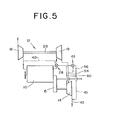
- an internal combustion engine 10 is equipped with both a turbo-charger 12 and an auxiliary turbine 14.
- the auxiliary turbine 14 is geared to the crankshaft 11 of the engine 10 through a combination of a reduction gear and an overrunning clutch (which allows the engine to outrun the auxiliary turbine without driving same) 15.
- the turbo-charger has a compressor 16 which is drivingly connected to a turbine 18 by a drive shaft 20.
- the turbine 18 is driven by the hot exhaust gases emitted from the combustion chamber 22 of the engine 10 and which are directed thereto through an exhaust passage 24.
- a first waste gate or by-pass 28 is provided in the exhaust passage 24.
- This waste gate takes the form of a valve 30 operated by a pressure differential responsive motor 32.
- This motor includes a diaphragm 34 which hermetically seperates an atmospheric chamber 36 and a pressure chamber 38.
- the pressure chamber 38 fluidly communicates with the induction passage 26 through a passage or conduit 40.
- a second waste gate or by-pass 42 is also provided downstream of the turbo-charger turbine 18 for relieving, via a by-pass passage 45, any excess back pressure which may develop between said turbine 18 and the auxiliary turbine 14, into an exhaust conduit 43 communicating with the discharge side of the auxiliary turbine 14.
- This second waste gate 42 like the first, includes a valve 44 which is operated by a pressure differential responsive motor 46.
- This motor also has a diaphragm 48 which hermetically divides a pressure chamber 50 and an atmospheric chamber 52. In this case the pressure chamber 52 is fluidly communicated with a transfer passage 54 interconnecting the turbine 18 and the auxiliary turbine 14 via a conduit or passage 56.
- the auxiliary turbine 14 is provided with a "double entry" (dual) scroll 58 which is adapted to seperately receive both the exhaust gases from the first waste gate via by-pass passage 60 and the exhaust gases from the turbo-charger turbine 18 through passage 54.
- the scroll is provided with a partition 62 which divides the scroll into two asymmetrical passages 64, 66 which respectively communicate with passages 60 and 54.
- the cross-section and configuration of each passage is different and so selected as to direct the respective flows passing therethrough, toward the blades 68 of the auxiliary turbine so as to impinge thereon with the optimal angle of incidence.
- the pulsations in each do not interfer with each other and thus do not induce any filling and emptying losses or the like.
- the first waste gate 28 is closed due to the lack of sufficient pressure in the pressure chamber 38 to overcome the combined bias of the atmospheric pressure and the spring 70 in the atmospheric chamber 36.
- the second wate gate 42 is also closed at this time, so that substantially all of the exhaust gases discharged from the combustion chamber 22 are directed through the turo-charger turbine 18 and transfer passage 54 via turbine 14 into the exhaust conduit 43.
- the back pressure developed downstream of the turbo-charger turbine 18 is relatively low, thus allowing for a high expansion rate across same, which induces an according high supercharging pressure in the induction passage 26 and in turn increases the torque output of the engine 10 under these conditions.
- the first waste gate When the supercharging pressure reaches a predetermine level (for example 300-1800 mmHg) the first waste gate is opened. viz., when the supercharging pressure (or compressor 16 discharge pressure) has reached a level sufficient to overcome the bias of the spring 70 and atmospheric pressure in the atmospheric chamber 36, a portion of the exhaust gases discharged from the engine is thus allowed to flow through the by-pass passage 60 into the scroll passage 64 and subsequently to the auxiliary turbine. The remaining portion of the exhaust gases of course continues to flow through the turbine 18, conduit 56 and passage 66 to the auxiliary turbine.
- a predetermine level for example 300-1800 mmHg
- the opening of the second waste gate 42 allows the excessive back pressure to be relieved into the exhaust conduit 43 via the passage 54, thus preventing an inevitable engine torque output reduction by reducing the back pressure acting on the turbo-charger turbine 18.
- the auxiliary turbine adds to the engine output via the supply of exhaust gases thereto through both of the passages 54 and 60.
Landscapes
- Engineering & Computer Science (AREA)
- Chemical & Material Sciences (AREA)
- Combustion & Propulsion (AREA)
- Mechanical Engineering (AREA)
- General Engineering & Computer Science (AREA)
- Supercharger (AREA)
Applications Claiming Priority (2)
| Application Number | Priority Date | Filing Date | Title |
|---|---|---|---|
| JP1980132519U JPS5754622U (de) | 1980-09-17 | 1980-09-17 | |
| JP132519/80U | 1980-09-17 |
Publications (3)
| Publication Number | Publication Date |
|---|---|
| EP0048027A2 true EP0048027A2 (de) | 1982-03-24 |
| EP0048027A3 EP0048027A3 (en) | 1982-09-08 |
| EP0048027B1 EP0048027B1 (de) | 1985-01-16 |
Family
ID=15083211
Family Applications (1)
| Application Number | Title | Priority Date | Filing Date |
|---|---|---|---|
| EP81107329A Expired EP0048027B1 (de) | 1980-09-17 | 1981-09-16 | Turbo-compound-Brennkraftmaschine |
Country Status (4)
| Country | Link |
|---|---|
| US (1) | US4391098A (de) |
| EP (1) | EP0048027B1 (de) |
| JP (1) | JPS5754622U (de) |
| DE (1) | DE3168328D1 (de) |
Cited By (5)
| Publication number | Priority date | Publication date | Assignee | Title |
|---|---|---|---|---|
| WO2007138325A3 (en) * | 2006-05-31 | 2008-01-17 | Cummins Turbo Tech Ltd | Turbocharger with dualwastegate |
| CN104234819A (zh) * | 2013-06-10 | 2014-12-24 | 福特环球技术公司 | 用于二元流涡轮控制的方法和系统 |
| EP3061941A1 (de) * | 2015-02-27 | 2016-08-31 | AVL Powertrain Engineering, Inc. | Turbo-compounding-motor-system |
| FR3044364A1 (fr) * | 2015-11-30 | 2017-06-02 | Valeo Systemes De Controle Moteur | Systeme moteur avec systeme de recuperation d'energie et circuit basse pression de recirculation des gaz brules |
| US10662903B2 (en) | 2015-02-27 | 2020-05-26 | Avl Powertrain Engineering, Inc. | Waste heat recovery and boost systems including variable drive mechanisms |
Families Citing this family (21)
| Publication number | Priority date | Publication date | Assignee | Title |
|---|---|---|---|---|
| US4557674A (en) * | 1983-06-30 | 1985-12-10 | Arnett Jr Robert D | Flow sensing speed control for pressure fluid motor |
| DE3335856C2 (de) * | 1983-10-03 | 1987-03-05 | BBC Aktiengesellschaft Brown, Boveri & Cie., Baden, Aargau | Abgasturboladersystem an einem aufgeladenem Verbrennungsmotor |
| US4694654A (en) * | 1983-10-29 | 1987-09-22 | Isuzu Motors Limited | Exhaust energy recovery and generator for use with an engine |
| CH658884A5 (fr) * | 1984-10-01 | 1986-12-15 | Cerac Inst Sa | Groupe moteur a combustion interne. |
| JPS6299634A (ja) * | 1985-10-24 | 1987-05-09 | Isuzu Motors Ltd | タ−ボコンパウンド内燃機関 |
| US4815282A (en) * | 1987-02-24 | 1989-03-28 | Teledyne Industries, Inc. | Turbocharged compund cycle ducted fan engine system |
| JPH0637852B2 (ja) * | 1989-07-17 | 1994-05-18 | いすゞ自動車株式会社 | 4サイクル断熱エンジン |
| US5119633A (en) * | 1990-09-25 | 1992-06-09 | Cummins Engine Company, Inc. | Power turbine bypass for improved compression braking |
| US5329770A (en) * | 1993-05-06 | 1994-07-19 | Ward Michael S | Exhaust gas turbine drive system for engine accessories |
| US5799489A (en) * | 1996-06-28 | 1998-09-01 | Hyundai Motor Company, Ltd. | Torque compensating apparatus and method for a turbo-charger |
| US7269950B2 (en) * | 2004-05-05 | 2007-09-18 | Precision Industries, Inc. | Staged turbocharger |
| US7644585B2 (en) * | 2004-08-31 | 2010-01-12 | The United States Of America As Represented By The Administrator Of The U.S. Environmental Protection Agency | Multi-stage turbocharging system with efficient bypass |
| GB2430708B (en) * | 2005-10-03 | 2010-09-22 | Ford Global Tech Llc | Turbo charging in a variable displacement engine |
| DE102008064521B4 (de) * | 2008-12-18 | 2021-05-20 | Dr. Ing. H.C. F. Porsche Aktiengesellschaft | Brennkraftmaschine mit Abgasturbolader |
| US8640459B2 (en) * | 2009-10-23 | 2014-02-04 | GM Global Technology Operations LLC | Turbocharger control systems and methods for improved transient performance |
| RU2573075C2 (ru) * | 2011-04-21 | 2016-01-20 | Мак Тракс, Инк. | Силовая установка с байпасом турбины и способ ее эксплуатации |
| US8813494B2 (en) * | 2011-09-07 | 2014-08-26 | General Electric Company | Method and system for a turbocharged engine |
| US8899040B2 (en) | 2011-09-29 | 2014-12-02 | Caterpillar Inc. | Compressor bypass |
| US20140331656A1 (en) * | 2013-05-10 | 2014-11-13 | Achates Power, Inc. | Air Handling Constructions With Turbo-Compounding For Opposed-Piston Engines |
| CN105464769B (zh) * | 2015-12-30 | 2017-11-17 | 东风商用车有限公司 | 一种双流道动力涡轮系统及其控制方法 |
| RU168499U1 (ru) * | 2016-06-23 | 2017-02-07 | Федеральное государственное унитарное предприятие "Центральный институт авиационного моторостроения имени П.И. Баранова" | Выносной вентиляторный модуль авиационной силовой установки |
Family Cites Families (7)
| Publication number | Priority date | Publication date | Assignee | Title |
|---|---|---|---|---|
| CH202931A (de) * | 1937-03-25 | 1939-02-15 | Maschf Augsburg Nuernberg Ag | Brennkraftmaschine mit Spülung und Aufladung, insbesondere für Höhenflug. |
| US2245163A (en) * | 1939-04-07 | 1941-06-10 | Gen Electric | Power plant for aircraft |
| US3007302A (en) * | 1958-09-30 | 1961-11-07 | Continental Aviat & Eng Corp | Compound turbine-diesel power plant |
| US3906729A (en) * | 1974-03-25 | 1975-09-23 | Caterpillar Tractor Co | Multiple turbocharger system |
| US4100742A (en) * | 1976-12-09 | 1978-07-18 | The United States Of America As Represented By The Secretary Of The Army | Turbocompound engine with turbocharger control |
| US4179892A (en) | 1977-12-27 | 1979-12-25 | Cummins Engine Company, Inc. | Internal combustion engine with exhaust gas recirculation |
| JPS5512012U (de) * | 1978-07-07 | 1980-01-25 |
-
1980
- 1980-09-17 JP JP1980132519U patent/JPS5754622U/ja active Pending
-
1981
- 1981-09-08 US US06/300,115 patent/US4391098A/en not_active Expired - Lifetime
- 1981-09-16 DE DE8181107329T patent/DE3168328D1/de not_active Expired
- 1981-09-16 EP EP81107329A patent/EP0048027B1/de not_active Expired
Cited By (10)
| Publication number | Priority date | Publication date | Assignee | Title |
|---|---|---|---|---|
| WO2007138325A3 (en) * | 2006-05-31 | 2008-01-17 | Cummins Turbo Tech Ltd | Turbocharger with dualwastegate |
| US8336309B2 (en) | 2006-05-31 | 2012-12-25 | Cummins Turbo Technologies Limited | Turbocharger with dual wastegate |
| CN104234819A (zh) * | 2013-06-10 | 2014-12-24 | 福特环球技术公司 | 用于二元流涡轮控制的方法和系统 |
| US9850811B2 (en) | 2013-06-10 | 2017-12-26 | Ford Global Technologies, Llc | Method and system for binary flow turbine control |
| CN104234819B (zh) * | 2013-06-10 | 2018-06-26 | 福特环球技术公司 | 用于二元流涡轮控制的方法和系统 |
| EP3061941A1 (de) * | 2015-02-27 | 2016-08-31 | AVL Powertrain Engineering, Inc. | Turbo-compounding-motor-system |
| US10072562B2 (en) | 2015-02-27 | 2018-09-11 | Avl Powertrain Engineering, Inc. | Engine turbo-compounding system |
| US10662903B2 (en) | 2015-02-27 | 2020-05-26 | Avl Powertrain Engineering, Inc. | Waste heat recovery and boost systems including variable drive mechanisms |
| FR3044364A1 (fr) * | 2015-11-30 | 2017-06-02 | Valeo Systemes De Controle Moteur | Systeme moteur avec systeme de recuperation d'energie et circuit basse pression de recirculation des gaz brules |
| WO2017093661A1 (fr) * | 2015-11-30 | 2017-06-08 | Valeo Systemes De Controle Moteur | Systeme moteur avec systeme de recuperation d'energie et circuit basse pression de recirculation des gaz brules |
Also Published As
| Publication number | Publication date |
|---|---|
| EP0048027B1 (de) | 1985-01-16 |
| DE3168328D1 (en) | 1985-02-28 |
| EP0048027A3 (en) | 1982-09-08 |
| US4391098A (en) | 1983-07-05 |
| JPS5754622U (de) | 1982-03-30 |
Similar Documents
| Publication | Publication Date | Title |
|---|---|---|
| US4391098A (en) | Turbo-compound internal combustion engine | |
| US5904045A (en) | Hydropneumatic engine supercharger system | |
| US4083188A (en) | Engine turbocharger system | |
| EP2494173B1 (de) | Strategie zur steuerung eines motors | |
| US4389845A (en) | Turbine casing for turbochargers | |
| US5121607A (en) | Energy recovery system for large motor vehicles | |
| US6694735B2 (en) | Internal combustion engine with an exhaust turbocharger and an exhaust-gas recirculation device | |
| US4586337A (en) | Turbocompound system | |
| US5241817A (en) | Screw engine with regenerative braking | |
| US4339922A (en) | Dual turbine turbo-supercharger | |
| US4478043A (en) | Method for controlling the operation of an hydraulic assist turbocharger | |
| US3559397A (en) | Turbo supercharger control mechanism | |
| KR19990036017A (ko) | 모터보조 가변기하학 터보차저 시스템 | |
| US5142867A (en) | Compound turbo-drive for an internal-combustion engine | |
| GB2034815A (en) | Supercharge internal-combustion engine | |
| US5113658A (en) | Hydraulic assist turbocharger system | |
| GB2038940A (en) | Exhaust By-pass Valve Apparatus for Double Entry Type I.C. Engine Turbocharger | |
| US20120152214A1 (en) | Turbocharger system | |
| US3355878A (en) | Turbocompressor system | |
| US10344763B2 (en) | Disc turbo charger | |
| US20040055299A1 (en) | Method and device for operating an exhaust gas turbocharger | |
| US3143849A (en) | Internal combustion engines | |
| GB2088964A (en) | Dual Turbine Turbo Charger | |
| JPS60116821A (ja) | 排気タ−ビン過給機 | |
| WO1980000169A1 (en) | A vehicle combustion engine of the compound type |
Legal Events
| Date | Code | Title | Description |
|---|---|---|---|
| PUAI | Public reference made under article 153(3) epc to a published international application that has entered the european phase |
Free format text: ORIGINAL CODE: 0009012 |
|
| AK | Designated contracting states |
Designated state(s): DE FR GB |
|
| PUAL | Search report despatched |
Free format text: ORIGINAL CODE: 0009013 |
|
| AK | Designated contracting states |
Designated state(s): DE FR GB |
|
| 17P | Request for examination filed |
Effective date: 19820909 |
|
| GRAA | (expected) grant |
Free format text: ORIGINAL CODE: 0009210 |
|
| AK | Designated contracting states |
Designated state(s): DE FR GB |
|
| REF | Corresponds to: |
Ref document number: 3168328 Country of ref document: DE Date of ref document: 19850228 |
|
| ET | Fr: translation filed | ||
| RAP2 | Party data changed (patent owner data changed or rights of a patent transferred) |
Owner name: NISSAN MOTOR CO., LTD. |
|
| PLBI | Opposition filed |
Free format text: ORIGINAL CODE: 0009260 |
|
| 26 | Opposition filed |
Opponent name: DAIMLER-BENZ AKTIENGESELLSCHAFT Effective date: 19851016 |
|
| RAP2 | Party data changed (patent owner data changed or rights of a patent transferred) |
Owner name: DAIMLER BENZ AKTIENGESELLSCHAFT Owner name: NISSAN MOTOR CO., LTD. |
|
| RAP2 | Party data changed (patent owner data changed or rights of a patent transferred) |
Owner name: NISSAN MOTOR CO., LTD. |
|
| RAP2 | Party data changed (patent owner data changed or rights of a patent transferred) |
Owner name: DAIMLER BENZ AKTIENGESELLSCHAFT Owner name: NISSAN MOTOR CO., LTD. |
|
| RAP2 | Party data changed (patent owner data changed or rights of a patent transferred) |
Owner name: DAIMLER BENZ AKTIENGESELLSCHAFT Owner name: NISSAN MOTOR CO., LTD. |
|
| REG | Reference to a national code |
Ref country code: GB Ref legal event code: 732 |
|
| REG | Reference to a national code |
Ref country code: FR Ref legal event code: TP |
|
| PLBM | Termination of opposition procedure: date of legal effect published |
Free format text: ORIGINAL CODE: 0009276 |
|
| STAA | Information on the status of an ep patent application or granted ep patent |
Free format text: STATUS: OPPOSITION PROCEDURE CLOSED |
|
| 27C | Opposition proceedings terminated |
Effective date: 19870713 |
|
| REG | Reference to a national code |
Ref country code: FR Ref legal event code: TP |
|
| PGFP | Annual fee paid to national office [announced via postgrant information from national office to epo] |
Ref country code: GB Payment date: 19950822 Year of fee payment: 15 |
|
| PGFP | Annual fee paid to national office [announced via postgrant information from national office to epo] |
Ref country code: FR Payment date: 19950918 Year of fee payment: 15 |
|
| PGFP | Annual fee paid to national office [announced via postgrant information from national office to epo] |
Ref country code: DE Payment date: 19951120 Year of fee payment: 15 |
|
| PG25 | Lapsed in a contracting state [announced via postgrant information from national office to epo] |
Ref country code: GB Effective date: 19960916 |
|
| PG25 | Lapsed in a contracting state [announced via postgrant information from national office to epo] |
Ref country code: FR Effective date: 19960930 |
|
| GBPC | Gb: european patent ceased through non-payment of renewal fee |
Effective date: 19960916 |
|
| PG25 | Lapsed in a contracting state [announced via postgrant information from national office to epo] |
Ref country code: DE Effective date: 19970603 |
|
| REG | Reference to a national code |
Ref country code: FR Ref legal event code: ST |
|
| REG | Reference to a national code |
Ref country code: FR Ref legal event code: ST |