EP0048042A2 - Sicherheitsvorrichtung für Schalter mit Federantrieb, die fahrbar in einer Zelle sind - Google Patents
Sicherheitsvorrichtung für Schalter mit Federantrieb, die fahrbar in einer Zelle sind Download PDFInfo
- Publication number
- EP0048042A2 EP0048042A2 EP81200925A EP81200925A EP0048042A2 EP 0048042 A2 EP0048042 A2 EP 0048042A2 EP 81200925 A EP81200925 A EP 81200925A EP 81200925 A EP81200925 A EP 81200925A EP 0048042 A2 EP0048042 A2 EP 0048042A2
- Authority
- EP
- European Patent Office
- Prior art keywords
- breaker
- lever
- projection
- springs
- movement
- Prior art date
- Legal status (The legal status is an assumption and is not a legal conclusion. Google has not performed a legal analysis and makes no representation as to the accuracy of the status listed.)
- Granted
Links
- 230000000717 retained effect Effects 0.000 description 4
- 238000012423 maintenance Methods 0.000 description 1
- 238000012986 modification Methods 0.000 description 1
- 230000004048 modification Effects 0.000 description 1
Images


Classifications
-
- H—ELECTRICITY
- H02—GENERATION; CONVERSION OR DISTRIBUTION OF ELECTRIC POWER
- H02B—BOARDS, SUBSTATIONS OR SWITCHING ARRANGEMENTS FOR THE SUPPLY OR DISTRIBUTION OF ELECTRIC POWER
- H02B11/00—Switchgear having carriage withdrawable for isolation
-
- H—ELECTRICITY
- H02—GENERATION; CONVERSION OR DISTRIBUTION OF ELECTRIC POWER
- H02B—BOARDS, SUBSTATIONS OR SWITCHING ARRANGEMENTS FOR THE SUPPLY OR DISTRIBUTION OF ELECTRIC POWER
- H02B11/00—Switchgear having carriage withdrawable for isolation
- H02B11/12—Switchgear having carriage withdrawable for isolation with isolation by horizontal withdrawal
- H02B11/127—Withdrawal mechanism
- H02B11/133—Withdrawal mechanism with interlock
Definitions
- This invention relates to a spring-controlled electric circuit breaker arranged in a housing cubicle, in which it can be moved and from which it can also be completely withdrawn.
- the invention relates to a safety device for such a circuit breaker able to be moved in its compartment in the housing cubicle, in which it can assume an inserted position or an isolated position.
- Said lever incorporated in the breaker is operationally connected to the mobile breaker contacts in such a manner that it assumes a position in which it retains said member in its position of greater projection when the breaker contacts are closed, and assumes a second- position in which it enables said member to be moved into its position of lesser projection when the contacts are open.
- electric circuit breakers of this type are provided with closure springs which are always kept in their loaded state by suitable motor means, in order to cause the mobile contacts to trip into their closed position at the required moment.
- closure springs become unloaded by virtue of the closure of the contacts, but immediately afterwards the motor means reload them so that they are ready for a subsequent operation.
- Suitable locking means keep the closure springs in the loaded state, and it is by acting on these means that the springs are unloaded, with consequent closure of the contacts. Said locking means are operated generally mechanically.
- the object of the present invention is to obviate this danger by means of a safety device which automatically unloads the closure springs before the breaker is moved from its inserted position to its isolated position and from this latter to its withdrawn position.
- the device according to the present invention ensures that each time the breaker is moved from its inserted or isolated position, its closure springs are automatically unloaded.
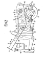
- the reference numeral 10 indicates a part of the circuit breaker casing.
- a shaft 11 carries a freely rotatable lever 12 which by means of a tie bar 13 is connected to the mobile contact (not shown) of the breaker.
- a lever 15 pivoted at 16 is engaged with the lever 12 by means of a slotted link connection 14, and its free end 17 is able to cooperate with a pin l8 mounted so that it can move along its axis in the breaker casing 10.
- the pin l8 projects lowerly from the casing 10 and can assume a position of greater projection ( Figures 1 and 2) and a position of lesser projection ( Figure 3). This latter position can be assumed by the pin 18 only if the lever 15 is rotated clockwise about its pivot 16, i.e. if the lever 12 is rotated anticlockwise about the shaft 11, this latter rotation taking place when the mobile contacts are moved from their closed position (Figure 1) into their open position ( Figures 2 and 3).
- the shaft 11 carries a freely rotatable second lever 19, which at its free end carries a U-shaped pusher 20 pivoted at 21 to the lever 19.
- An arm of the pusher 20 can act against a roller 22 carried by the lever 12, whereas on the other arm of the pusher 20 there can act a lever 23 which possesses a surface 24 against which said second arm of the pusher 20 abuts.
- the cam 26 is arranged to act on a roller 28 carried by the lever 19.
- the shaft 25 also rigidly carries two discs 29, between which there is eccentrically mounted a roller 30 against which a pusher 31 pivoted at 32 to the breaker casing can abut.
- a further pusher 34 is mounted freely rotatable about the shaft 25, and can abut by means of one end against the roller 28 carried by the lever 19, its other end being connected by a telescopic rod 35 to the lever 12.
- a switch 39 operable by the pin l8 is mounted on the casing 10, said switch being connected into the circuit of the motor means (not shown) which load the closure spring 27 by acting on the shaft 25.
- the motor means When the pin 18 is in its position of greater projection ( Figures 1 and 2) it keeps the switch 39 closed, the switch being opened when the pin 18 is in its position of lesser projection ( Figure 3).
- the motor means When in this latter state, the motor means are unable to reload the closure spring.
- the pin l8 must be released in order to enable it to rise. This can be done only by intentionally opening the breaker contacts. To do this, the lever 23 must be moved in the direction of the arrow indicated in Figure 1.
- the controls for this action are normally provided in the breaker and are not shown. The consequence of this action is a rotation of the pusher 20 about its pivot 21, so that that arm thereof which abuts against the roller 22 carried by the lever 12 frees this roller and thus releases the lever 12 from the lever 19. In this manner, the opening springs (not shown) which act on the mobile contacts are able to operate and open the contacts.
- the lever 12 which is no longer retained by the pusher 20 is lowered by means of the tie bar 13.
- the rotation of the lever 12 about the shaft 11 causes an analogous rotation of the pusher 34 about the shaft 25 by way of the telescopic rod 35, so that said pusher 34 is freed from the roller 28 so that it releases the lever 19.
- the lever 19 now rotates anticlockwise about the shaft 11, dragging with it the U pusher 20.
- the pusher 20 is guided by the surface 24 of the lever 23.
- the lowering of the lever 19 terminates when the roller 28 carried by it reaches the lowest point of the contour of the cam 26, and the lowering movement of the lever 12 is induced by the opening movement of the mobile contacts.
- the circuit breaker can now be moved from the inserted position into the isolated position, and can also be completely extracted from ' its compartment in the housing cubicle.
- the device according to the invention ensures in a simple and reliable manner that the closure springs are unloaded after intentional opening of the contacts, before moving the circuit breaker from its inserted or isolated position.
- the device can undergo various modifications without leaving the scope of the inventive idea.
- the telescopic rod 33 instead of being connected to the lever 23, the telescopic rod 33 can be connected to the bell crank lever 36, obviously by suitably adjusting its loadless stroke.
Landscapes
- Engineering & Computer Science (AREA)
- Power Engineering (AREA)
- Breakers (AREA)
Priority Applications (1)
| Application Number | Priority Date | Filing Date | Title |
|---|---|---|---|
| AT81200925T ATE8550T1 (de) | 1980-09-17 | 1981-08-20 | Sicherheitsvorrichtung fuer schalter mit federantrieb, die fahrbar in einer zelle sind. |
Applications Claiming Priority (2)
| Application Number | Priority Date | Filing Date | Title |
|---|---|---|---|
| IT2471880 | 1980-09-17 | ||
| IT2471880A IT1209262B (it) | 1980-09-17 | 1980-09-17 | Dispositivo di sicurezza per interruttori elettrici con comando a molle traslabili in un armadio di custodia. |
Publications (3)
| Publication Number | Publication Date |
|---|---|
| EP0048042A2 true EP0048042A2 (de) | 1982-03-24 |
| EP0048042A3 EP0048042A3 (en) | 1982-08-04 |
| EP0048042B1 EP0048042B1 (de) | 1984-07-18 |
Family
ID=11214500
Family Applications (1)
| Application Number | Title | Priority Date | Filing Date |
|---|---|---|---|
| EP19810200925 Expired EP0048042B1 (de) | 1980-09-17 | 1981-08-20 | Sicherheitsvorrichtung für Schalter mit Federantrieb, die fahrbar in einer Zelle sind |
Country Status (8)
| Country | Link |
|---|---|
| EP (1) | EP0048042B1 (de) |
| AR (1) | AR227205A1 (de) |
| AT (1) | ATE8550T1 (de) |
| BR (1) | BR8105939A (de) |
| DE (1) | DE3164880D1 (de) |
| IT (1) | IT1209262B (de) |
| MX (1) | MX151697A (de) |
| NZ (1) | NZ198376A (de) |
Cited By (6)
| Publication number | Priority date | Publication date | Assignee | Title |
|---|---|---|---|---|
| FR2581805A1 (fr) * | 1985-05-07 | 1986-11-14 | Merlin Gerin | Disjoncteur debrochable multipolaire equipe d'un dispositif de desarmement et de declenchement automatique lors de l'extraction |
| EP0951122A1 (de) * | 1998-04-17 | 1999-10-20 | Schneider Electric Industries SA | Steuergerät für die Entladung und Entkupplung einer Energieakkumulators während das Trennen einer trennbaren Schalters |
| DE102004021455B4 (de) * | 2003-05-16 | 2005-10-27 | Siemens Ag | Niederspannungs-Leistungsschalter |
| EP1968091A3 (de) * | 2007-03-08 | 2010-08-18 | LS Industrial Systems Co., Ltd | Automatische Entladevorrichtung für eine Verschlussfeder in einem Luftleistungsschalter und Luftleistungsschalter damit |
| EP2884606A1 (de) * | 2013-12-16 | 2015-06-17 | LSIS Co., Ltd. | Einschub- Leistungsschalter |
| US10199182B1 (en) | 2017-10-31 | 2019-02-05 | Siemens Aktiengesellschaft | Switch, in particular low-voltage circuit breaker, in plug-in technology with automatic unloading of the force store during withdrawal |
Family Cites Families (3)
| Publication number | Priority date | Publication date | Assignee | Title |
|---|---|---|---|---|
| FR1282775A (fr) * | 1960-01-18 | 1962-01-27 | Westinghouse Electric Corp | Mécanisme de manceuvre pour disjoncteurs |
| US3072763A (en) * | 1960-02-15 | 1963-01-08 | Allis Chalmers Mfg Co | Spring actuated contact opening and closing mechanism |
| IT1132041B (it) * | 1980-07-31 | 1986-06-25 | Ansaldo Sa | Dispositivo per la translazione di un interruttore elettrico nel suo armadio di custodia |
-
1980
- 1980-09-17 IT IT2471880A patent/IT1209262B/it active
-
1981
- 1981-08-20 DE DE8181200925T patent/DE3164880D1/de not_active Expired
- 1981-08-20 AT AT81200925T patent/ATE8550T1/de not_active IP Right Cessation
- 1981-08-20 EP EP19810200925 patent/EP0048042B1/de not_active Expired
- 1981-09-08 MX MX189088A patent/MX151697A/es unknown
- 1981-09-15 AR AR28676981A patent/AR227205A1/es active
- 1981-09-16 NZ NZ198376A patent/NZ198376A/en unknown
- 1981-09-16 BR BR8105939A patent/BR8105939A/pt unknown
Cited By (11)
| Publication number | Priority date | Publication date | Assignee | Title |
|---|---|---|---|---|
| FR2581805A1 (fr) * | 1985-05-07 | 1986-11-14 | Merlin Gerin | Disjoncteur debrochable multipolaire equipe d'un dispositif de desarmement et de declenchement automatique lors de l'extraction |
| EP0951122A1 (de) * | 1998-04-17 | 1999-10-20 | Schneider Electric Industries SA | Steuergerät für die Entladung und Entkupplung einer Energieakkumulators während das Trennen einer trennbaren Schalters |
| FR2777696A1 (fr) * | 1998-04-17 | 1999-10-22 | Schneider Electric Ind Sa | Dispositif de commande de la decharge et du debrayage d'un accumulateur d'energie lors de l'extraction d'un disjoncteur debrochable |
| US6177641B1 (en) | 1998-04-17 | 2001-01-23 | Schneider Electric Sa | Plug-in circuit breaker discharge and disengagement energy storage control device used during extraction of breaker |
| DE102004021455B4 (de) * | 2003-05-16 | 2005-10-27 | Siemens Ag | Niederspannungs-Leistungsschalter |
| US7129430B2 (en) | 2003-05-16 | 2006-10-31 | Siemens Aktiengesellschaft | Low-voltage circuit breaker |
| EP1968091A3 (de) * | 2007-03-08 | 2010-08-18 | LS Industrial Systems Co., Ltd | Automatische Entladevorrichtung für eine Verschlussfeder in einem Luftleistungsschalter und Luftleistungsschalter damit |
| US7977595B2 (en) | 2007-03-08 | 2011-07-12 | Ls Industrial Systems Co., Ltd. | Automatic discharging apparatus for closing spring in air circuit breaker and air circuit breaker having the same |
| EP2884606A1 (de) * | 2013-12-16 | 2015-06-17 | LSIS Co., Ltd. | Einschub- Leistungsschalter |
| US9425590B2 (en) | 2013-12-16 | 2016-08-23 | Lsis Co., Ltd. | Withdrawable-type circuit breaker |
| US10199182B1 (en) | 2017-10-31 | 2019-02-05 | Siemens Aktiengesellschaft | Switch, in particular low-voltage circuit breaker, in plug-in technology with automatic unloading of the force store during withdrawal |
Also Published As
| Publication number | Publication date |
|---|---|
| ATE8550T1 (de) | 1984-08-15 |
| EP0048042B1 (de) | 1984-07-18 |
| IT8024718A0 (it) | 1980-09-17 |
| BR8105939A (pt) | 1982-06-08 |
| EP0048042A3 (en) | 1982-08-04 |
| IT1209262B (it) | 1989-07-16 |
| DE3164880D1 (en) | 1984-08-23 |
| NZ198376A (en) | 1985-07-12 |
| MX151697A (es) | 1985-02-01 |
| AR227205A1 (es) | 1982-09-30 |
Similar Documents
| Publication | Publication Date | Title |
|---|---|---|
| US4286242A (en) | Mechanical interlock for low voltage circuit breakers | |
| JPH11502669A (ja) | 安全スイッチ | |
| WO1995018457A1 (en) | Safety switch assemblies | |
| EP0048042B1 (de) | Sicherheitsvorrichtung für Schalter mit Federantrieb, die fahrbar in einer Zelle sind | |
| GB2180995A (en) | Latching resetting and lockout of a circuit interrupter switch | |
| GB1222456A (en) | A current-limiting circuit breaker | |
| US5012214A (en) | Lock mechanism for a limiting contact maker | |
| US5293521A (en) | Protective relay switch having trap door | |
| EP1575074B1 (de) | Schaltermechanismus | |
| US5339060A (en) | Protective switch | |
| US3769477A (en) | Switch operating mechanism | |
| US5014025A (en) | Actuator-accessory reset arrangement for molded case circuit interrupter or electric switch | |
| US6307455B1 (en) | Control mechanism for a circuit breaker | |
| GB819697A (en) | Improvements in operating mechanism for an electric circuit breaker | |
| EA000520B1 (ru) | Управляющий механизм прерывателя электрической цепи | |
| US7129430B2 (en) | Low-voltage circuit breaker | |
| US4845324A (en) | Interrupter operating mechanism | |
| US4739136A (en) | Control device of a high voltage circuit breaker equipped with closing resistors | |
| US4238750A (en) | Mechanical trip device for a circuit breaker | |
| KR100195425B1 (ko) | 연결분리 및 인터럽터 링키지의 조정을 위한 인터럽터 스위치 | |
| GB1080983A (en) | Improvements in or relating to electric switchgear | |
| KR100323738B1 (ko) | 기중차단기의 안전장치 | |
| EP1535791B1 (de) | Vorrichtung zur Betätigung von Lasttrennschaltern für Stromversorgungsleitungen, insbesondere für Bahnstromversorgung | |
| US1287545A (en) | Electric switch. | |
| US2843703A (en) | Fuse protective system |
Legal Events
| Date | Code | Title | Description |
|---|---|---|---|
| PUAI | Public reference made under article 153(3) epc to a published international application that has entered the european phase |
Free format text: ORIGINAL CODE: 0009012 |
|
| AK | Designated contracting states |
Designated state(s): AT BE CH DE FR GB LU NL SE |
|
| PUAL | Search report despatched |
Free format text: ORIGINAL CODE: 0009013 |
|
| AK | Designated contracting states |
Designated state(s): AT BE CH DE FR GB LU NL SE |
|
| 17P | Request for examination filed |
Effective date: 19820712 |
|
| GRAA | (expected) grant |
Free format text: ORIGINAL CODE: 0009210 |
|
| AK | Designated contracting states |
Designated state(s): AT BE CH DE FR GB LI LU NL SE |
|
| REF | Corresponds to: |
Ref document number: 8550 Country of ref document: AT Date of ref document: 19840815 Kind code of ref document: T |
|
| REF | Corresponds to: |
Ref document number: 3164880 Country of ref document: DE Date of ref document: 19840823 |
|
| PG25 | Lapsed in a contracting state [announced via postgrant information from national office to epo] |
Ref country code: LU Free format text: LAPSE BECAUSE OF NON-PAYMENT OF DUE FEES Effective date: 19840831 |
|
| ET | Fr: translation filed | ||
| PGFP | Annual fee paid to national office [announced via postgrant information from national office to epo] |
Ref country code: DE Payment date: 19840928 Year of fee payment: 4 Ref country code: CH Payment date: 19840928 Year of fee payment: 4 |
|
| PGFP | Annual fee paid to national office [announced via postgrant information from national office to epo] |
Ref country code: SE Payment date: 19840930 Year of fee payment: 4 Ref country code: BE Payment date: 19840930 Year of fee payment: 4 |
|
| PGFP | Annual fee paid to national office [announced via postgrant information from national office to epo] |
Ref country code: FR Payment date: 19841030 Year of fee payment: 4 |
|
| PLBE | No opposition filed within time limit |
Free format text: ORIGINAL CODE: 0009261 |
|
| STAA | Information on the status of an ep patent application or granted ep patent |
Free format text: STATUS: NO OPPOSITION FILED WITHIN TIME LIMIT |
|
| 26N | No opposition filed | ||
| PGFP | Annual fee paid to national office [announced via postgrant information from national office to epo] |
Ref country code: AT Payment date: 19850814 Year of fee payment: 5 |
|
| PGFP | Annual fee paid to national office [announced via postgrant information from national office to epo] |
Ref country code: NL Payment date: 19850831 Year of fee payment: 5 |
|
| PG25 | Lapsed in a contracting state [announced via postgrant information from national office to epo] |
Ref country code: AT Effective date: 19860820 |
|
| PG25 | Lapsed in a contracting state [announced via postgrant information from national office to epo] |
Ref country code: SE Effective date: 19860821 |
|
| PG25 | Lapsed in a contracting state [announced via postgrant information from national office to epo] |
Ref country code: LI Effective date: 19860831 Ref country code: CH Effective date: 19860831 |
|
| BERE | Be: lapsed |
Owner name: ANSALDO S.P.A. Effective date: 19860831 |
|
| PG25 | Lapsed in a contracting state [announced via postgrant information from national office to epo] |
Ref country code: NL Effective date: 19870301 |
|
| NLV4 | Nl: lapsed or anulled due to non-payment of the annual fee | ||
| GBPC | Gb: european patent ceased through non-payment of renewal fee | ||
| PG25 | Lapsed in a contracting state [announced via postgrant information from national office to epo] |
Ref country code: FR Free format text: LAPSE BECAUSE OF NON-PAYMENT OF DUE FEES Effective date: 19870430 |
|
| REG | Reference to a national code |
Ref country code: CH Ref legal event code: PL |
|
| PG25 | Lapsed in a contracting state [announced via postgrant information from national office to epo] |
Ref country code: DE Effective date: 19870501 |
|
| REG | Reference to a national code |
Ref country code: FR Ref legal event code: ST |
|
| PG25 | Lapsed in a contracting state [announced via postgrant information from national office to epo] |
Ref country code: GB Effective date: 19881118 |
|
| PG25 | Lapsed in a contracting state [announced via postgrant information from national office to epo] |
Ref country code: BE Effective date: 19890831 |
|
| EUG | Se: european patent has lapsed |
Ref document number: 81200925.6 Effective date: 19870812 |