EP0048048A1 - Wärmetauscher mit mehreren senkrechten Röhren für den Aufwärtstransport eines ersten Wärmetauschermediums - Google Patents
Wärmetauscher mit mehreren senkrechten Röhren für den Aufwärtstransport eines ersten Wärmetauschermediums Download PDFInfo
- Publication number
- EP0048048A1 EP0048048A1 EP81200947A EP81200947A EP0048048A1 EP 0048048 A1 EP0048048 A1 EP 0048048A1 EP 81200947 A EP81200947 A EP 81200947A EP 81200947 A EP81200947 A EP 81200947A EP 0048048 A1 EP0048048 A1 EP 0048048A1
- Authority
- EP
- European Patent Office
- Prior art keywords
- pipes
- medium
- openings
- stabilisation
- flow
- Prior art date
- Legal status (The legal status is an assumption and is not a legal conclusion. Google has not performed a legal analysis and makes no representation as to the accuracy of the status listed.)
- Granted
Links
- 230000006641 stabilisation Effects 0.000 claims abstract description 29
- 239000011236 particulate material Substances 0.000 claims abstract description 7
- 238000011105 stabilization Methods 0.000 abstract 3
- 230000000903 blocking effect Effects 0.000 abstract 1
- 238000010276 construction Methods 0.000 description 3
- 238000000034 method Methods 0.000 description 3
- 239000002245 particle Substances 0.000 description 3
- 239000007787 solid Substances 0.000 description 3
- 238000005192 partition Methods 0.000 description 2
- 230000015556 catabolic process Effects 0.000 description 1
- 239000012141 concentrate Substances 0.000 description 1
- 238000009434 installation Methods 0.000 description 1
- 239000000463 material Substances 0.000 description 1
- 238000012216 screening Methods 0.000 description 1
- 238000005406 washing Methods 0.000 description 1
- XLYOFNOQVPJJNP-UHFFFAOYSA-N water Substances O XLYOFNOQVPJJNP-UHFFFAOYSA-N 0.000 description 1
Images


Classifications
-
- F—MECHANICAL ENGINEERING; LIGHTING; HEATING; WEAPONS; BLASTING
- F28—HEAT EXCHANGE IN GENERAL
- F28D—HEAT-EXCHANGE APPARATUS, NOT PROVIDED FOR IN ANOTHER SUBCLASS, IN WHICH THE HEAT-EXCHANGE MEDIA DO NOT COME INTO DIRECT CONTACT
- F28D13/00—Heat-exchange apparatus using a fluidised bed
-
- B—PERFORMING OPERATIONS; TRANSPORTING
- B01—PHYSICAL OR CHEMICAL PROCESSES OR APPARATUS IN GENERAL
- B01J—CHEMICAL OR PHYSICAL PROCESSES, e.g. CATALYSIS OR COLLOID CHEMISTRY; THEIR RELEVANT APPARATUS
- B01J8/00—Chemical or physical processes in general, conducted in the presence of fluids and solid particles; Apparatus for such processes
- B01J8/18—Chemical or physical processes in general, conducted in the presence of fluids and solid particles; Apparatus for such processes with fluidised particles
- B01J8/1836—Heating and cooling the reactor
-
- F—MECHANICAL ENGINEERING; LIGHTING; HEATING; WEAPONS; BLASTING
- F28—HEAT EXCHANGE IN GENERAL
- F28F—DETAILS OF HEAT-EXCHANGE AND HEAT-TRANSFER APPARATUS, OF GENERAL APPLICATION
- F28F19/00—Preventing the formation of deposits or corrosion, e.g. by using filters or scrapers
- F28F19/01—Preventing the formation of deposits or corrosion, e.g. by using filters or scrapers by using means for separating solid materials from heat-exchange fluids, e.g. filters
Definitions
- the invention relates to a heat exchanger having a plurality of vertical pipes for upward passage of a first heat-exchanging medium, at least one compartment for passage of a second heat-exchanging medium through which said pipes extend, a lower chamber through which said first medium passes and into which said pipes open for admission to the pipes of said first medium and a flow distribution element adapted to distribute the flow of the first medium in the lower chamber to the pipes.
- a fluidisable particulate material is present which, in operation of the heat exchanger, is maintained in a fluidised state in the pipes by the flow of the first medium.
- the pipes have inlet elements extending downwardly into said lower chamber with their lowermost ends open. Stabilisation openings are provided from the lower chamber into the inlet elements above the lowermost ends of the elements.
- a heat exchanger of the kind described above is disclosed in published Dutch patent application no. 7703939 (GB 1,592,232).
- the first heat exchanging medium is conducted through a mass of fluidised particulate material in a number of vertical pipes
- particular care must always be taken as to the stability of the process. If preferred flows occur through one or a few of the pipes the fluidised material will expand in these pipes and move over to the other pipes via a common upper box into which all the pipes open. The mass of fluidised particles will then collapse in these other pipes so that the flow of the first heat exchanging medium will be concentrated entirely in the pipe or pipes of preferred flow. This leads to the heat exchanger operating only partially and less than optimally, and increases the likelihood of the pipe walls being dirtied.
- the object of the invention is to prevent or minimize destabilisation caused by such blockages.
- the blockage is caused when solids are formed and deposited elsewhere in the system, particularly at the top of the heat exchanger.
- the solids may, for example, consist of boiler fur or scale which first forms against a wall and then is released from it in the form of lumps or flakes. This release may be caused by temperature variations in the installation, when the boiler fur lumps or flakes fall from the wall into the fluidised bed and usually remain floating in it.
- such lumps may temporarily move downwards and end up in the lower chamber, where they may remain floating around the inlet elements. In the course of time this may lead to collection at one or more of the stabilisation openings, with the final result that it is clogged.
- stabilisation openings are generally very much smaller than the main inlet openings in the inlet elements, a disproportionately large part of the flow of the first medium has been found to pass through the stabilisation openings.
- the blockage of an opening of this kind also has direct consequences on the speed of flow in the pipe concerned and therefore on the degree of expansion in the particulate material in that pipe, leading in turn to instability.
- the present invention consists in that the stabilisation openings are separated ouside the inlet elements, from the lowest inlet openings of these inlet elements by at least one screen which allows flow of the first medium to the stabilisation openings.
- the apertures of the screen should preferably be smaller than the longitudinal dimensions of the stabilisation openings.
- the screen prevents solids arriving in the lower chamber from reaching the neighbourhood of the stabilisation openings, unless their dimensions are so small that they can pass through the screen. In that case, however, they will also pass through the stabilisation openings without dirtying them and alowing them to clog.
- the area of the screen will usually be appreciably larger than the total area of the stabilisation openings.
- the risk of the screen silting up is therefore substantially less than for the stabilisation openings themselves. Nonetheless this risk can be still further reduced by increasing the surface area of the screen.
- It may, for example, have the shape of a basket enclosing the stabilisation openings.
- Another possibility is for the screen to have a box shape, with top, bottom and sides around the stabilisation openings.
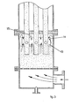
- This heat exchanger has a compartment 1 through which a second heat exchanging medium flows.
- the supply and discharge openings for this are not shown in the figure.
- the compartment 1 is separated by a partition 2 from a lower chamber or box 3 into which a number of vertical pipes 4 open.
- the pipes 4 extend vertically upwardly through the compartment 1.
- the lower box 3 is in direct connection via a perforated base plate 5 with a distribution box 6, into which a supply opening 7 opens out.
- the plate 5 acts as a distribution element which achieves a more uniform flow of the first medium to the pipes 4.
- a discharge opening 8 is also shown; this is closed off under normal operation but can be used for washing the apparatus through.
- the lower box 3 and the pipes 4 contain a mass of particulate material 9 which is fluidised when the first heat exchanging medium flows upwards from the supply opening 7 through the distribution box 6, the base plate 5, the chest beneath 9 and the pipes 4.
- the perforations in the base plate 5 are dimensioned so that the fluidisable particles cannot pass into the distribution box 6 and in operation the speed of the flow of the first heat exchanging medium is set sufficiently high that these particles remain in the fluidised state both in the lower box 3 and in the pipes 4.
- these are equipped with inlet pieces or extensions 10 which extend downwardly into the fluidised mass 9 in the lower chamber to the open lower ends 12.
- Stabilisation openings 11 are provided in the walls of the inlet pieces. A leakage flow of the first heat exchanging medium through the stabilisation openings equalises the level of the granular mass in the lower box, which produces a more regular flow in each of the pipes.
- a screen 13 e.g. a wire gauze
- This screen extends the full width of the lower box 3 and thus separates the openings 11 from the ends 12 of the pipes (outside the pipes 4). Flakes of boiler fur or other coarse dirt are held back by this screen 13 and cannot block the stabilisation openings 11.
- FIG. 2 A slightly different construction is shown in Fig. 2. Apart from the screen 13, this construction corresponds entirely to that of Fig. 1. Instead of a flat horizontal screen 13, a screen in the shape of a basket is fitted, consisting of a base 13 which does not extend across the entire transverse area of the lower box 3 but at its edge is joined to a skirt 14 which is fastened at its top edge to the partition 2. The screen area is thereby appreciably enlarged so that, as indicated by the arrows, the first heat-exchanging medium can spread over a larger area when passing through the screen. The likelihood of this screen being fouled and silting up is therefore appreciably reduced.
- FIG. 3 yet another embodiment in accordance with the invention is shown in Fig. 3. Again, this is the same as that of Figs. 1 and 2 except for the screen 13, which here has a box-shape, enclosing all the stabilisation openings 11.
- this screen has a base 13 below the level of the openings 11, a side wall 14 extending around the openings 11 and a horizontal top 15 above the level of the openings 11. Not only does this construction further enlarge the screening area but also the screen need now not be fastened to the wall 2. It may now be slid over the pipes 4 as a separate element, and fixed to them.
Landscapes
- Engineering & Computer Science (AREA)
- Chemical & Material Sciences (AREA)
- Physics & Mathematics (AREA)
- Thermal Sciences (AREA)
- Mechanical Engineering (AREA)
- General Engineering & Computer Science (AREA)
- Combustion & Propulsion (AREA)
- Organic Chemistry (AREA)
- Chemical Kinetics & Catalysis (AREA)
- Heat-Exchange Devices With Radiators And Conduit Assemblies (AREA)
- Catching Or Destruction (AREA)
- Basic Packing Technique (AREA)
- Pinball Game Machines (AREA)
Priority Applications (1)
| Application Number | Priority Date | Filing Date | Title |
|---|---|---|---|
| AT81200947T ATE3331T1 (de) | 1980-09-05 | 1981-08-27 | Waermetauscher mit mehreren senkrechten roehren fuer den aufwaertstransport eines ersten waermetauschermediums. |
Applications Claiming Priority (2)
| Application Number | Priority Date | Filing Date | Title |
|---|---|---|---|
| NL8005022 | 1980-09-05 | ||
| NLAANVRAGE8005022,A NL188598C (nl) | 1980-09-05 | 1980-09-05 | Warmtewisselaar van het type omvattende een bundel vertikale pijpen voor opwaarts transport van een eerste een fluidiseerbare korrelmassa doorstromend warmtewisselend medium. |
Publications (2)
| Publication Number | Publication Date |
|---|---|
| EP0048048A1 true EP0048048A1 (de) | 1982-03-24 |
| EP0048048B1 EP0048048B1 (de) | 1983-05-11 |
Family
ID=19835829
Family Applications (1)
| Application Number | Title | Priority Date | Filing Date |
|---|---|---|---|
| EP81200947A Expired EP0048048B1 (de) | 1980-09-05 | 1981-08-27 | Wärmetauscher mit mehreren senkrechten Röhren für den Aufwärtstransport eines ersten Wärmetauschermediums |
Country Status (10)
| Country | Link |
|---|---|
| US (1) | US4401152A (de) |
| EP (1) | EP0048048B1 (de) |
| JP (1) | JPS5933829B2 (de) |
| AT (1) | ATE3331T1 (de) |
| CA (1) | CA1162911A (de) |
| DE (1) | DE3160273D1 (de) |
| ES (1) | ES505195A0 (de) |
| FI (1) | FI69924C (de) |
| IL (1) | IL63650A (de) |
| NL (1) | NL188598C (de) |
Cited By (1)
| Publication number | Priority date | Publication date | Assignee | Title |
|---|---|---|---|---|
| EP0065332A1 (de) * | 1981-05-12 | 1982-11-24 | Esmil B.V. | Vorrichtung und Verfahren zur Konzentration einer Flüssigkeit durch Verdampfung |
Families Citing this family (1)
| Publication number | Priority date | Publication date | Assignee | Title |
|---|---|---|---|---|
| US4554963A (en) * | 1983-08-19 | 1985-11-26 | Baker International Corporation | Method and apparatus for a fluidized bed heat exchanger |
Citations (6)
| Publication number | Priority date | Publication date | Assignee | Title |
|---|---|---|---|---|
| FR1179572A (fr) * | 1957-07-11 | 1959-05-26 | Pechiney | Procédé et appareil pour le chauffage et le refroidissement des poudres |
| US2919118A (en) * | 1954-11-05 | 1959-12-29 | Combustion Eng | Air heater |
| DE1169420B (de) * | 1960-07-11 | 1964-05-06 | Universal Oil Prod Co | Hochtemperaturreaktor |
| US3441139A (en) * | 1966-09-16 | 1969-04-29 | Maurice D Mccormick | Motor coolant filter |
| FR2253196A1 (de) * | 1973-11-30 | 1975-06-27 | Pieper Gustav | |
| DE2613835A1 (de) * | 1975-04-01 | 1976-10-14 | Tokyo Shibaura Electric Co | Kuehlwasser verwendender waermeaustauscher |
Family Cites Families (1)
| Publication number | Priority date | Publication date | Assignee | Title |
|---|---|---|---|---|
| US4300625A (en) * | 1975-01-21 | 1981-11-17 | Mikhailov Gerold M | Preventing deposition on the inner surfaces of heat exchange apparatus |
-
1980
- 1980-09-05 NL NLAANVRAGE8005022,A patent/NL188598C/xx not_active IP Right Cessation
-
1981
- 1981-08-18 US US06/294,022 patent/US4401152A/en not_active Expired - Lifetime
- 1981-08-24 IL IL63650A patent/IL63650A/xx unknown
- 1981-08-24 CA CA000384493A patent/CA1162911A/en not_active Expired
- 1981-08-27 DE DE8181200947T patent/DE3160273D1/de not_active Expired
- 1981-08-27 AT AT81200947T patent/ATE3331T1/de not_active IP Right Cessation
- 1981-08-27 EP EP81200947A patent/EP0048048B1/de not_active Expired
- 1981-09-01 FI FI812700A patent/FI69924C/fi not_active IP Right Cessation
- 1981-09-03 JP JP56137861A patent/JPS5933829B2/ja not_active Expired
- 1981-09-04 ES ES505195A patent/ES505195A0/es active Granted
Patent Citations (6)
| Publication number | Priority date | Publication date | Assignee | Title |
|---|---|---|---|---|
| US2919118A (en) * | 1954-11-05 | 1959-12-29 | Combustion Eng | Air heater |
| FR1179572A (fr) * | 1957-07-11 | 1959-05-26 | Pechiney | Procédé et appareil pour le chauffage et le refroidissement des poudres |
| DE1169420B (de) * | 1960-07-11 | 1964-05-06 | Universal Oil Prod Co | Hochtemperaturreaktor |
| US3441139A (en) * | 1966-09-16 | 1969-04-29 | Maurice D Mccormick | Motor coolant filter |
| FR2253196A1 (de) * | 1973-11-30 | 1975-06-27 | Pieper Gustav | |
| DE2613835A1 (de) * | 1975-04-01 | 1976-10-14 | Tokyo Shibaura Electric Co | Kuehlwasser verwendender waermeaustauscher |
Cited By (1)
| Publication number | Priority date | Publication date | Assignee | Title |
|---|---|---|---|---|
| EP0065332A1 (de) * | 1981-05-12 | 1982-11-24 | Esmil B.V. | Vorrichtung und Verfahren zur Konzentration einer Flüssigkeit durch Verdampfung |
Also Published As
| Publication number | Publication date |
|---|---|
| ATE3331T1 (de) | 1983-05-15 |
| NL188598C (nl) | 1992-08-03 |
| NL188598B (nl) | 1992-03-02 |
| FI69924C (fi) | 1986-05-26 |
| IL63650A0 (en) | 1981-11-30 |
| FI812700L (fi) | 1982-03-06 |
| US4401152A (en) | 1983-08-30 |
| CA1162911A (en) | 1984-02-28 |
| EP0048048B1 (de) | 1983-05-11 |
| JPS5777899A (en) | 1982-05-15 |
| NL8005022A (nl) | 1982-04-01 |
| FI69924B (fi) | 1985-12-31 |
| DE3160273D1 (en) | 1983-06-16 |
| ES8206830A1 (es) | 1982-08-16 |
| ES505195A0 (es) | 1982-08-16 |
| JPS5933829B2 (ja) | 1984-08-18 |
| IL63650A (en) | 1984-05-31 |
Similar Documents
| Publication | Publication Date | Title |
|---|---|---|
| EP0132873B1 (de) | Vorrichtung zur Durchführung von physischen und/oder chemischen Verfahren, insbesondere ein kontinuierlicher Wärmetauscher | |
| FI68461B (fi) | Vaermevaexlare | |
| EP0437028B2 (de) | Teilchenabscheider nach dem Aufprallprinzip | |
| JPS6316966B2 (de) | ||
| US3253650A (en) | Heat-exchange apparatus | |
| US2888140A (en) | Filter baffles | |
| JPS61249511A (ja) | 粒状材床ろ過器の水回収装置 | |
| EP0048048B1 (de) | Wärmetauscher mit mehreren senkrechten Röhren für den Aufwärtstransport eines ersten Wärmetauschermediums | |
| EP0070591B1 (de) | Apparat für das in Kontakt bringen eines Fluidums mit einem körnigen Feststoffmaterial | |
| JPH08501868A (ja) | 格子要素 | |
| US2626129A (en) | Liquid distributor for cooling apparatus | |
| US4304753A (en) | Apparatus for performing physical and/or chemical processes involving at least one liquid, e.g., a heat exchanger | |
| SE501362C2 (sv) | Sätt och anordning att optimera flödet genom ett granulärt bäddfilter | |
| US6109342A (en) | Apparatus for carrying out a physical and/or chemical process, such as a heat exchanger | |
| RU2117226C1 (ru) | Установка для сушки сыпучих материалов, преимущественно зерна | |
| US7141219B1 (en) | Apparatus for carrying out a physical and/or chemical process, such as heat exchanger | |
| CA1329338C (en) | Fluidized bed heat exchanger and method of operating same |
Legal Events
| Date | Code | Title | Description |
|---|---|---|---|
| PUAI | Public reference made under article 153(3) epc to a published international application that has entered the european phase |
Free format text: ORIGINAL CODE: 0009012 |
|
| 17P | Request for examination filed |
Effective date: 19810827 |
|
| AK | Designated contracting states |
Designated state(s): AT BE CH DE FR GB IT LI SE |
|
| ITF | It: translation for a ep patent filed | ||
| GRAA | (expected) grant |
Free format text: ORIGINAL CODE: 0009210 |
|
| AK | Designated contracting states |
Designated state(s): AT BE CH DE FR GB IT LI SE |
|
| REF | Corresponds to: |
Ref document number: 3331 Country of ref document: AT Date of ref document: 19830515 Kind code of ref document: T |
|
| REF | Corresponds to: |
Ref document number: 3160273 Country of ref document: DE Date of ref document: 19830616 |
|
| ET | Fr: translation filed | ||
| PLBE | No opposition filed within time limit |
Free format text: ORIGINAL CODE: 0009261 |
|
| STAA | Information on the status of an ep patent application or granted ep patent |
Free format text: STATUS: NO OPPOSITION FILED WITHIN TIME LIMIT |
|
| 26N | No opposition filed | ||
| PGFP | Annual fee paid to national office [announced via postgrant information from national office to epo] |
Ref country code: AT Payment date: 19900709 Year of fee payment: 10 |
|
| PGFP | Annual fee paid to national office [announced via postgrant information from national office to epo] |
Ref country code: GB Payment date: 19900711 Year of fee payment: 10 Ref country code: FR Payment date: 19900711 Year of fee payment: 10 |
|
| PGFP | Annual fee paid to national office [announced via postgrant information from national office to epo] |
Ref country code: SE Payment date: 19900716 Year of fee payment: 10 |
|
| PGFP | Annual fee paid to national office [announced via postgrant information from national office to epo] |
Ref country code: BE Payment date: 19900720 Year of fee payment: 10 |
|
| PGFP | Annual fee paid to national office [announced via postgrant information from national office to epo] |
Ref country code: CH Payment date: 19900723 Year of fee payment: 10 |
|
| PGFP | Annual fee paid to national office [announced via postgrant information from national office to epo] |
Ref country code: DE Payment date: 19900730 Year of fee payment: 10 |
|
| ITTA | It: last paid annual fee | ||
| PG25 | Lapsed in a contracting state [announced via postgrant information from national office to epo] |
Ref country code: GB Effective date: 19910827 Ref country code: AT Effective date: 19910827 |
|
| PG25 | Lapsed in a contracting state [announced via postgrant information from national office to epo] |
Ref country code: SE Effective date: 19910828 |
|
| PG25 | Lapsed in a contracting state [announced via postgrant information from national office to epo] |
Ref country code: LI Effective date: 19910831 Ref country code: CH Effective date: 19910831 Ref country code: BE Effective date: 19910831 |
|
| BERE | Be: lapsed |
Owner name: ESMIL B.V. Effective date: 19910831 |
|
| GBPC | Gb: european patent ceased through non-payment of renewal fee | ||
| PG25 | Lapsed in a contracting state [announced via postgrant information from national office to epo] |
Ref country code: FR Effective date: 19920430 |
|
| REG | Reference to a national code |
Ref country code: CH Ref legal event code: PL |
|
| REG | Reference to a national code |
Ref country code: FR Ref legal event code: ST |
|
| PG25 | Lapsed in a contracting state [announced via postgrant information from national office to epo] |
Ref country code: DE Effective date: 19920801 |
|
| EUG | Se: european patent has lapsed |
Ref document number: 81200947.0 Effective date: 19920306 |