EP0048052B2 - Procédé pour couper un film en polymère et dispositif pour couper des bandes - Google Patents
Procédé pour couper un film en polymère et dispositif pour couper des bandes Download PDFInfo
- Publication number
- EP0048052B2 EP0048052B2 EP81200972A EP81200972A EP0048052B2 EP 0048052 B2 EP0048052 B2 EP 0048052B2 EP 81200972 A EP81200972 A EP 81200972A EP 81200972 A EP81200972 A EP 81200972A EP 0048052 B2 EP0048052 B2 EP 0048052B2
- Authority
- EP
- European Patent Office
- Prior art keywords
- cutting
- disc
- indexing
- film
- blade
- Prior art date
- Legal status (The legal status is an assumption and is not a legal conclusion. Google has not performed a legal analysis and makes no representation as to the accuracy of the status listed.)
- Expired - Lifetime
Links
Images

Classifications
-
- B—PERFORMING OPERATIONS; TRANSPORTING
- B26—HAND CUTTING TOOLS; CUTTING; SEVERING
- B26D—CUTTING; DETAILS COMMON TO MACHINES FOR PERFORATING, PUNCHING, CUTTING-OUT, STAMPING-OUT OR SEVERING
- B26D7/00—Details of apparatus for cutting, cutting-out, stamping-out, punching, perforating, or severing by means other than cutting
- B26D7/20—Cutting beds
-
- B—PERFORMING OPERATIONS; TRANSPORTING
- B26—HAND CUTTING TOOLS; CUTTING; SEVERING
- B26D—CUTTING; DETAILS COMMON TO MACHINES FOR PERFORATING, PUNCHING, CUTTING-OUT, STAMPING-OUT OR SEVERING
- B26D1/00—Cutting through work characterised by the nature or movement of the cutting member or particular materials not otherwise provided for; Apparatus or machines therefor; Cutting members therefor
- B26D1/0006—Cutting members therefor
-
- B—PERFORMING OPERATIONS; TRANSPORTING
- B26—HAND CUTTING TOOLS; CUTTING; SEVERING
- B26D—CUTTING; DETAILS COMMON TO MACHINES FOR PERFORATING, PUNCHING, CUTTING-OUT, STAMPING-OUT OR SEVERING
- B26D1/00—Cutting through work characterised by the nature or movement of the cutting member or particular materials not otherwise provided for; Apparatus or machines therefor; Cutting members therefor
- B26D1/01—Cutting through work characterised by the nature or movement of the cutting member or particular materials not otherwise provided for; Apparatus or machines therefor; Cutting members therefor involving a cutting member which does not travel with the work
- B26D1/02—Cutting through work characterised by the nature or movement of the cutting member or particular materials not otherwise provided for; Apparatus or machines therefor; Cutting members therefor involving a cutting member which does not travel with the work having a stationary cutting member
- B26D1/025—Cutting through work characterised by the nature or movement of the cutting member or particular materials not otherwise provided for; Apparatus or machines therefor; Cutting members therefor involving a cutting member which does not travel with the work having a stationary cutting member for thin material, e.g. for sheets, strips or the like
-
- B—PERFORMING OPERATIONS; TRANSPORTING
- B26—HAND CUTTING TOOLS; CUTTING; SEVERING
- B26D—CUTTING; DETAILS COMMON TO MACHINES FOR PERFORATING, PUNCHING, CUTTING-OUT, STAMPING-OUT OR SEVERING
- B26D1/00—Cutting through work characterised by the nature or movement of the cutting member or particular materials not otherwise provided for; Apparatus or machines therefor; Cutting members therefor
- B26D1/0006—Cutting members therefor
- B26D2001/006—Cutting members therefor the cutting blade having a special shape, e.g. a special outline, serrations
-
- B—PERFORMING OPERATIONS; TRANSPORTING
- B26—HAND CUTTING TOOLS; CUTTING; SEVERING
- B26D—CUTTING; DETAILS COMMON TO MACHINES FOR PERFORATING, PUNCHING, CUTTING-OUT, STAMPING-OUT OR SEVERING
- B26D5/00—Arrangements for operating and controlling machines or devices for cutting, cutting-out, stamping-out, punching, perforating, or severing by means other than cutting
- B26D5/02—Means for moving the cutting member into its operative position for cutting
-
- B—PERFORMING OPERATIONS; TRANSPORTING
- B26—HAND CUTTING TOOLS; CUTTING; SEVERING
- B26D—CUTTING; DETAILS COMMON TO MACHINES FOR PERFORATING, PUNCHING, CUTTING-OUT, STAMPING-OUT OR SEVERING
- B26D7/00—Details of apparatus for cutting, cutting-out, stamping-out, punching, perforating, or severing by means other than cutting
- B26D7/08—Means for treating work or cutting member to facilitate cutting
-
- Y—GENERAL TAGGING OF NEW TECHNOLOGICAL DEVELOPMENTS; GENERAL TAGGING OF CROSS-SECTIONAL TECHNOLOGIES SPANNING OVER SEVERAL SECTIONS OF THE IPC; TECHNICAL SUBJECTS COVERED BY FORMER USPC CROSS-REFERENCE ART COLLECTIONS [XRACs] AND DIGESTS
- Y10—TECHNICAL SUBJECTS COVERED BY FORMER USPC
- Y10S—TECHNICAL SUBJECTS COVERED BY FORMER USPC CROSS-REFERENCE ART COLLECTIONS [XRACs] AND DIGESTS
- Y10S83/00—Cutting
- Y10S83/929—Particular nature of work or product
- Y10S83/949—Continuous or wound supply
-
- Y—GENERAL TAGGING OF NEW TECHNOLOGICAL DEVELOPMENTS; GENERAL TAGGING OF CROSS-SECTIONAL TECHNOLOGIES SPANNING OVER SEVERAL SECTIONS OF THE IPC; TECHNICAL SUBJECTS COVERED BY FORMER USPC CROSS-REFERENCE ART COLLECTIONS [XRACs] AND DIGESTS
- Y10—TECHNICAL SUBJECTS COVERED BY FORMER USPC
- Y10S—TECHNICAL SUBJECTS COVERED BY FORMER USPC CROSS-REFERENCE ART COLLECTIONS [XRACs] AND DIGESTS
- Y10S83/00—Cutting
- Y10S83/955—Cutter edge shiftable to present different portion of edge
-
- Y—GENERAL TAGGING OF NEW TECHNOLOGICAL DEVELOPMENTS; GENERAL TAGGING OF CROSS-SECTIONAL TECHNOLOGIES SPANNING OVER SEVERAL SECTIONS OF THE IPC; TECHNICAL SUBJECTS COVERED BY FORMER USPC CROSS-REFERENCE ART COLLECTIONS [XRACs] AND DIGESTS
- Y10—TECHNICAL SUBJECTS COVERED BY FORMER USPC
- Y10T—TECHNICAL SUBJECTS COVERED BY FORMER US CLASSIFICATION
- Y10T83/00—Cutting
- Y10T83/647—With means to convey work relative to tool station
- Y10T83/6584—Cut made parallel to direction of and during work movement
- Y10T83/66—With means to press work to tool
-
- Y—GENERAL TAGGING OF NEW TECHNOLOGICAL DEVELOPMENTS; GENERAL TAGGING OF CROSS-SECTIONAL TECHNOLOGIES SPANNING OVER SEVERAL SECTIONS OF THE IPC; TECHNICAL SUBJECTS COVERED BY FORMER USPC CROSS-REFERENCE ART COLLECTIONS [XRACs] AND DIGESTS
- Y10—TECHNICAL SUBJECTS COVERED BY FORMER USPC
- Y10T—TECHNICAL SUBJECTS COVERED BY FORMER US CLASSIFICATION
- Y10T83/00—Cutting
- Y10T83/647—With means to convey work relative to tool station
- Y10T83/6584—Cut made parallel to direction of and during work movement
- Y10T83/6603—Tool shiftable relative to work-conveying means
-
- Y—GENERAL TAGGING OF NEW TECHNOLOGICAL DEVELOPMENTS; GENERAL TAGGING OF CROSS-SECTIONAL TECHNOLOGIES SPANNING OVER SEVERAL SECTIONS OF THE IPC; TECHNICAL SUBJECTS COVERED BY FORMER USPC CROSS-REFERENCE ART COLLECTIONS [XRACs] AND DIGESTS
- Y10—TECHNICAL SUBJECTS COVERED BY FORMER USPC
- Y10T—TECHNICAL SUBJECTS COVERED BY FORMER US CLASSIFICATION
- Y10T83/00—Cutting
- Y10T83/929—Tool or tool with support
- Y10T83/9493—Stationary cutter
Definitions
- This invention relates to a method of slit-cutting polymer films and to a device for carrying out the method.
- Various machines used for continuous production or processing of polymer films may require a continuous cutting operation to be performed at the moving polymer web, generally at a marginal area thereof and in longitudinal direction (parallel to machine direction), e.g. for continuously opening a blown polymer film hose at its sides so as to produce two separate polymer webs that can be wound up separately.
- a wider polymer web may require division into a number of parallel strips, or a web may require longitudinal side portions to be cut away, e.g. after coating, etc.
- Any such operation requires prolonged cutting of polymer films, generally at relatively high speeds, and dulling of the cutting edge must be prevented or controlled if undesired tearing or rupturing of the polymer film is to be prevented.
- press cutting or shear cutting devices comprising rotatable circular knives which, in press cutting, are pressed onto a counter-roller having an extremely hard surface or, in shear cutting, cooperate with a second rotatable circular knife to form a shear edge; in either case, the circular knives used must be of a rugged construction, i.e. have a substantial thicknes of several millimeters to support the stresses of coacting with the support roller or the second knife.
- the invention aims at preserving the advantages of the extremely sharp edge provided by such throw-away blades while minimizing or avoiding the problems caused by knife-dulling in prolonged continuous operation (e.g. 100 hours or more), notably when cutting polymer films that contain highly abrasive components, such as antiblocking agents.
- Preferred embodiments of the inventive method have the features of claims (2-3) the device for carrying out the method according to the invention is defined in claim 4 and preferred embodiments of the device have the features of claims (5-10).
- Blades or knives in the form of steel sheet discs having the features (a), (b) and (c) of claim 5 are believed to be novel per se and will be termed "indexing blade" herein; the indexing drive preferably includes a conventional step-motor.
- the step size can be defined in terms of angular degrees of a circle that encompasses 360°.
- the minimum length of the incremental cutting edge portions required in steps (B) and (C) of the inventive method is the thickness or gauge of the polymer film (10 to 500 pm).
- a moving web of polymer film may deviate somewhat from its theoretical plane of travel so that the location of the film-cutting position (or first point of contact between polymer film and cutting edge) may deviate somewhat from its theoretical position; the length of each incremental portion of the cutting edge will, typically, be in the range of from about 0.5 to 5 mm, preferably about 1 to 4 mm.
- each indexing step will involve changing of the angular position of the disc (viewed normally to the disc plane and with 360° for full turn) by shifting the angular position of the disc in steps of from about 1 ° to about 10°; typically, the disc thus provides from about 30 to about 300 discrete portions of the cutting edge that can be used in succession in the cutting position until the blade is exhausted.
- length of cutting operation could be quantified in terms of the geometrical length of the polymer film that has been cut; in practice, the length of the cutting time period is more convenient, notably as the speed of the web is frequently defined by a producing or processing plant where continuous cutting is required.
- length of cutting operation expressed in terms of "period of cutting time”
- an incremental cutting edge portion of an indexing blade of the device according to the invention having a Rockwell hardness C of at least 50 will have a cutting life in continuous operation in the order of, for example, from 100 to 2000 minutes with typical web speeds (10 to 150 meters/minute, e.g. 20 to 80 meters/minute) at film gauges in the 50 to 500 f..lm range and with various polymers containing abrasive additives.
- a typical indexing blade of the device according to the invention will have a cutting life in the range of days to weeks and some simple tests will be sufficient to establish optimized use periods for the incremental portions and the indexing blade.
- the length of the cutting operations is monitored, e.g. on a time basis or on the basis of the cut web length, for generating signals that can be used to automatically control the indexing "frequency", i.e. the operational distance between the subsequent changes of the angular blade position.
- indexing frequencies are given for illustration, the virtual infinity of variations in the polymer material-plus-additives systems may make it advisable to optimize the indexing frequency.
- indexing periods of below 50 minutes (between two subsequent shifts) will be the exception, while periods well above 1000 minutes have been found to be operable in many instances.
- the indexing drive e.g. step-motor
- the indexing drive is geared to produce or trigger such signal.
- a blade support member for easy blade exchange may be provided on the indexing drive, e.g. a magnetic plate and positioning means on the support member and/or the blade; preferably, the blade is provided with at least one perforation for cooperating with at least one corresponding protuberance, e.g. a pin or the like, on the blade support.
- the indexing blade must be refrained from rotating, such positioning means can serve as a lock for preventing blade rotation.
- the continuous cutting edge of indexing blades of the device according to the invention should be substantially as sharp as the cutting edge of conventional razor blades of comparable thickness.
- the term "provided with a razor-type edge" provides for a clear definition in the subject context and providing steel sheet in the required thickness range with a razor edge is known per se.
- novel indexing blades of the device according to the invention can be manufactured by conventional grinding and honing techniques but starting from circular or polygonal pieces of steel sheet meeting the required thickness and shape parameters, and further providing a finished hardness of at least about 50 RHC, e.g. 55 to 58 RHC.
- blade thickness and blade diameter preferably are correlated to avoid blade fluttering when used with a polymer film of a given thickness; for that reason, a blade thickness range of from 20 to 500 f..lm, more preferably of from 30 to 300 ⁇ m, and particularly of from 50 to 200 ⁇ m, is preferably combined with a diameter range of from about 20 to 60 mm.
- a diameter:thickness ratio of the indexing blades in the range of from about 100:1 to 3000:1 is suitable.
- Disc diameters below about 20 mm have the disadvantage of providing relatively few incremental cutting positions and diameters below 10 mm are not suitable for that purpose.
- an increased fluttering tendency may occur; this may be compensated by increasing the thickness within the limits given.
- the disc thickness-primarily geared to minimize film spreading upon and immediately after cutting- may have an impact upon blade fluttering in the sense that lower blade thicknesses tend to increase the flutting tendency. For that reason, a blade thickness in the lowest part (10 to 30 ⁇ m) of the range given is not preferred and a minimum blade thickness of at least 50pm is a more preferred lower limit. At the uppermost part (300 to 500 ⁇ m) of the blade thickness range fluttering is avoided but the blade may be too thick so that blade thicknesses in this uppermost region are not generally preferred and a preferred upper limit of blade thickness is 300 ⁇ m and even a blade thickness of below 200 ⁇ m will be suitable for most purposes of the invention, notably in the preferred diameter range.
- Blade fluttering may, of course, depend upon the speed of the motion of the film.
- margin cutting or web division in longitudinal or machine direction typical web speeds are in the range given above (10 to 150 m/min).
- polymer film is used herein to encompass webs or web portions of polymer films and comparable organic materials; generally, this implies a generally “flat” structure as is typical for moving webs of films in the plastics industry; this includes laminates in the thickness range given.
- polymer films or webs for use in the inventive method include single-layer webs and multi-layer webs provided that the total web thickness does not substantially exceed the 500 ⁇ m upper thickness limit.
- Webs in the form of tubular extrudates preferably are cut, after local spreading of mutually superimposed web layers if required, in single-layer mode; generally, the single-layer mode is preferred even though the "single layer" may be a laminate.
- the lower limit of the film thickness range (10 wm) is due mainly to practical reasons, such as lack of cohe- siveness and self-supporting strength of extremely thin films.
- Polymer includes homopolymers, copolymers, polymer mixtures and polymer compositions containing non-polymeric constituents, e.g. additives, dyes, plasticizers, etc.
- suitable polymers are polyolefins (e.g. polyethylene, polypropylene) including copolymers of such olefins (e.g. copolymers of ethylene and acrylic acid or vinyl chloride) and the so-called ionomers; polyhaloalkylenes, polyesters, polyamides; polyacrylates, polymethacrylates, polystyrene and styrene-based copolymers, polyvinylidene chloride, polyvinylidene fluorides.
- polyolefins e.g. polyethylene, polypropylene
- copolymers of such olefins e.g. copolymers of ethylene and acrylic acid or vinyl chloride
- ionomers e.g. copolymers of such
- the optimum upper limit of film thickness may be substantially below 500 ⁇ m.
- films of hard PVC shore A hardness of 90 or more
- films of hard PVC can be cut best when having a thickness of about 50 ⁇ m.
- polymer films suitable for use in the inventive method have a shore hardness (A, C or D) of up to about 90 or less and a ball-pressure hardness (German Industrial Standards DIN, in kg/cm 2 ) of up to about 1000 or less.
- Most thermoplastic polymers are suitable but films of regenerated cellulose, of chemically modified cellulose and of partially cross-linked polymers and the like are suitable as well as long as the films made thereof have a sufficient flexibility for processing as webs and have a hardness in the range just cited.
- Additives including abrasive types such as anti-blocking agents can be incorporated into the films; in fact, problems of continuously cutting such films with conventional cutting devices operating in the press-cutting, shear-cutting or rotation-cutting mode can be avoided entirely according to the invention by simply adapting the indexing frequency so that web ruptures, irregular edges and the like disadvantages of blade dulling do not occur.
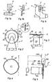
- the prior art cutting device 10 of Figure 1a comprises a circular knife 101 (shown in front view, upper portion broken away) rotatingly supported by a shaft (not shown) and in pressing engagement with an extremely hard rotating anvil or counter roller 102 (only a fragment being shown in section).
- the plane of the film that is cut is indicated as F in all Figures, that plane being assumed to extend normal to the plane of drawing, at least at the cutting point.
- a conventional shear-type cutter 11 is illustrated in Figure 1 b comprising an upper rotating circular knife 111 (fragment shown) that cooperates with a lower rotating circular knife 112 (fragment shown) to form an endless shearing edge.
- This is an example of the shear-cutting mode and, again, the knife edge angle a would be substantially greater than 10°.
- Figure 1c illustrates, for purposes of comparison, a cutting device 12 using a conventional razor blade 121.
- Such blades are known to have many uses other than for shaving and various devices for cutting with such blades are conventional; thus, Figure 1c is intended to show the result of using such blades for continuous cutting of polymer films.
- razor blade 121 can be arranged on a magnetic support 123 that holds blade 121 in cutting position and provides for easy replacement of used blades.
- a film-guiding means including, if desired, a spread 141 and a guide member 142 cooperates with blade 121.
- FIG. 1c Operation of device 12 in Figure 1c illustrates the slit cutting mode; physical contact between blade 121 and guide member 142 should be avoided as blade 121 has the thickness of a conventional razor blade, i.e. in the range of from about 40 to 100 f..lm, and is much too flexible for co-acting effectively with an anvil, counter-knife or the like counter-members used in press-cutting and shear-cutting.
- film guide means are preferred for slit cutting operation, notably when using this cutting mode for one-sided or two-sided splitting of tubular films produced by blow-extrusion methods of the type disclosed, for example, in U.S. Patent No. 2,668,323 to Johnson.
- razor blade 121 of the device shown in Fig. 1 c it is apparent that, as such blade has two parallel cutting edges, the practically feasible way of exchanging a blunted cutting edge of blade 121 is to reverse blade 121. Thereafter, a fresh blade is needed.
- each cutting edge of blade 121 might be used in incremental portions by manual displacement but with little or no positional control; in practice, this is impossible, however.
- the device 2 shown diagrammatically in a side-view in Figure 2 comprises an indexing blade in the form of a circular steel sheet disc 20 having a diameter of 45 mm and provided at its periphery 21 with a continuous or endless cutting edge 22.
- An enlarged portion of the peripheral part of disc 20 is shown in section in the circle connected with Figure 2: steel sheet disc 20 having a substantially uniform thickness of about 200 f..lm and a Rockwell hardness C in the range of from 50 to 58 presents a razor-sharp edge formed by two converging edge surfaces 22, 221 obtained, e.g. by grinding and honing.
- Surfaces 22, 221 are shown to be "planar", i.e. presenting a linear taper, but could be slightly curved, i.e. form a cutting edge with a concave taper or a convex taper as can be obtained by grinding and honing techniques conventionally used in production of razor blades.
- the angle a enclosed by surfaces 22, 221 in a linear taper will generally be below 10°, e.g. 8 to 9°.
- the radial length of surfaces 22, 221 will be about 4 to 6 times greater than the thickness of disc 20, regardless of the type of taper.
- steel sheet disc 20 is rigidly connected with a step-switching drive 25 (indicated in Figure 2 diagrammatically as a circle and also referred to as "actuator” herein) preferably, a stepping motor.
- a step-switching drive 25 (indicated in Figure 2 diagrammatically as a circle and also referred to as "actuator” herein) preferably, a stepping motor.
- Such motors are conventional in the step-switching art and provide for a predetermined angular displacement of an axis in response to a signal.
- Actuator 25 is, in turn, rigidly connected with a mounting plate 27 or equivalent mounting means for holding the indexing blade 20 in a web cutting position.
- the web plane is indicated by line F and is assumed to be normal to the plane of drawing moving continuously in a "downward" direction, i.e. downwards, from the upper side of Figure 2, and the indexing blade is kept stationary, both in planar and in axial direction once the position of mounting plate 27 is fixed, e.g. after moving into a desired position by sliding displacement on two rods (not shown) mounted on the frame of a web-processing machine (not shown) and securing in that position.
- the web-processing machine might be a group of web-moving rollers, connected with a blownhose extruder, a web-winding apparatus, a coating machine or the like requiring continuous longitudinal slitting or trimming of a polymer web.
- portion A of indexing blade 20 is in cutting position as depicted in Figure 2 and further assuming a typical speed of movement of web F of about 30 meters per minute: now, portion A will be held in cutting position as long as that portion remains sufficiently sharp for smooth cutting of web F.
- abrasive effect of web F e.g. its anti-blocking constituent and proportion thereof
- it may typically take about 500 minutes of cutting time i.e. 15000 meters of cutting length
- incremental edge portion A begins to loose its original sharpness by continued abrasion.
- a predetermined and safe (for continued smooth cutting) length of cutting operation would be about 250 minutes of cutting time or 7500 meters of cutting length with an abrasive film.
- This length may be determined by previous runs (operating instructions) or by a simple test run when a hitherto untried web material is to be cut.
- the predetermined value for a safe length (time-wise or length-wise) of cutting operation is used as a first or "step-trigger" indexing parameter, i.e. to trigger actuator 25.
- a suitable triggering arrangement will be given below.
- actuator 25 When actuator 25 is triggered, it will move an adjacent and fresh incremental portion of cutting edge 21 into cutting position. Assuming that the sense of operation of actuator 25 is anti-clockwise, the subsequent incremental portion indexed into the original position of A is cutting edge portion 23 which now remains in that position for the above explained safe cutting time or length of 250 minutes or 7500 meters and will be indexed out of cutting position by actuator 25 thereafter.
- a second indexing parameter is required that in effect determines the cutting life of the indexing blade, i.e. the number of indexing steps per full periphery of 360°.
- This second parameter determines the peripheral length of each incremental cutting edge portion, and while this length is dependent both upon the diameter of indexing blade 20 as well as upon the angular displacement of actuator 25 per switching step, it will be termed "angular" indexing parameter.
- each incremental cutting edge portion of about 1 mm will be sufficient for many cutting purposes and this length may be double if required for safety of continuous cutting, e.g. to compensate for minor deviations of the web from its theoretical plane of movement.
- the 45 mm diameter of indexing blade 20 having a peripheral length of about 140 mm may provide for 140 or 35 incremental portions corresponding with angular indexing parameters of 2.5° or 10°.
- the actuator 25, or its variable setting will have to provide for indexing blade 20 by 2.5 or 10 degrees per step in this example.
- conventional indexing actuators such as stepping motors provide for control, no further explanation is believed to be required here.
- generation of a signal that indicates complete or substantially complete indexing of blade 20 can be achieved by conventional means, e.g. standard design of stepping motors or stepping motor control.
- a contact in the actuator that is activated once per full turn may close a circuit that powers an optical or acoustical warning device such as a bell; for additional safety, a timer triggered in the same manner may interrupt operation of the machine that produces or moves web F.
- a web-guide that supports web F, e.g. in the position marked S.
- the support at S may have a plane or a curved surface. A physical contact between the web-guide at S and indexing blade 20 must be prevented, however.
- FIG. 3 Atop-view of device 2 of Figure 2 is shown in Figure 3 to illustrate that a generally normal position of indexing blade 20 relative to web F is preferred. It should be emphasized, however, that only that portion of web F at the cutting position A need be so oriented.
- a protecting shield 36 may be used for operating safety.
- the indexing actuator or stepping motor 25 is shown to consist of a drive 39 and a reduction gear 38; further, blade 20 is connected with gear 38 by a support plate 31 that may have one or more positioning pins (not shown) matching with corresponding perforations (not shown) of indexing blade 20.
- support plate 31 is a magnetic plate.
- Figure 4 illustrates a "substantially circular" indexing blade 40 in a polygonal (regular polygon) shape; preferably, the continuous cutting edge 42 at periphery 41 of blade 40 is subdivided to present at least twelve, and preferably more than twelve, linear segments, for example twentyfour or thirtysix segments. In general, one segment should be provided for each indexing step.
- Figure 5 indicates, in a diagrammatic top-view, two different positions of indexing blade 50 relative to two polymer film webs F 1 , F 2 , each of which is guided in a typical conformation.
- Web F 1 shows a side or edge portion of a normally compressed tubular film of the type produced by extrusion and subsequent inflation ("blow-extrusion") of the type mentioned above.
- Web F 2 is moved in planar conformation normal to blade 50.
- a film or web guide 58 is held in a stationary position, e.g. by being secured to the same mounting means (not shown) that holds actuator 55 and blade 50.
- Guide 58 has a recess 581 to receive blade 50 without contacting same, and an outlet 582 for blowing air into tubular web F 2 so as to facilitate spreading thereof. This is particularly advantageous when cutting up tubularfilms of very thin or rupture-sensitive polymer films. In practice, tubular films in an originally compressed or folded state will be cut up in two portions, e.g. at each folding edge, so that a pair of cutting devices will be used.
- a similar guide 58 (minus air outlet 582) can be used to guidingly support a web F 2 , moved in a generally planar configuration, at or near positions S indicated in Figures 2 and 3.
- Indexing blade 50 and actuator 55 of Figure 5 correspond with blade 20 and actuator 25 of Figures 2 and 3 and an actuator control 56 is shown to supply a triggering signal or impulse to actuator 55 in accordance with the first or step-triggering indexing parameter explained above.
- Actuator control 56 may be a timer device connected, if desired, with the drive (not shown) of the web producing or web processing plant. Alternatively, or complementary, the actuator control 56 may be connected with a conventional device 561, 562 for metering the length of a moving web so as to adapt the indexing frequency to a change of the speed of web movement.
- Indexing blade 60 is a steel sheet disc having a uniform thickness of 100 to 300 f..lm and a diameter of 30 to 60 mm.
- a continuous cutting edge 62 is provided at periphery 61 of blade 60 and a securing member 63 holds blade 60 in rigid connection with actuator 65 which is mounted on suppport 691 of slide-carriage 69.
- Carriage 69 is slideably mounted on a guide bar 67 of a web processing machine (not shown); rod 671 connected with carriage 69 is used to slightly pull the spreader device 68 towards the inner surface of one edge F 3 of a tubular film moving in downward direction. It is to be understood that rod 671 carries a second device 6 (not shown) in opposite position at the other edge (not shown ) of the tubular film extending from F 3 and beyond the right side of Figure 6.
- Spreader 68 is provided with an air-outlet 64 supplied with compressed air via line 66 and bores (broken lines) within carriage 69.
- a free-wheeling circular film guide 682 having a peripheral recess 681 for receiving an edge portion of indexing blade 60 but without contacting the latter in the same general manner as explained in connection with Figure 5 is provided so that edge F 3 of the tubular film will be guided into cutting position A.
- indexing blade 60 is not moved except when indexed for removing an incremental portion of cutting edge 62 from cutting position A and for introducing a fresh subsequent incremental cutting edge portion into that position.
- each incremental portion of cutting edge 62 will have a peripheral length in the range of typically 1 to 10° providing for 36 to 360 incremental edge portions for indexing into, and out of, cutting position A.
- the total cutting time of indexing blade 60 will be in the range of from 9000 to 90,000 minutes; as each indexing motion of blade 60 is substantially momentary and, typically, last for a second only, the aggregated total time of indexing motion during complete indexing of blade 60 will amount from 36 seconds to 6 minutes and thus has no effect upon cutting. Accordingly, there is no appreciable difference if indexing is clockwise or counter-clockwise.
- indexing blades of the device according to the invention can be obtained from sheets of tool- grade steel, e.g. steel sheets of the type conventionally used in the manufacture of razor blades.
- Typical examples are ferrous alloys containing carbon and chromium as the essential alloying elements.
- a steel containing about 0.4 %, by weight, of carbon and 13.5 %, by weight, of chromium is illustrative but numerous other types of cutting-grade steel are known and can be used for the indexing blades disclosed herein.
- a polymer film producing plant was modified as follows: Two indexing cutters 6 as illustrated in Fig. 6 were slidingly arranged on the frame-supported slide bar 67 of the withdrawing roller group of a conventional and commercially available blow extruder (Type A 90-32, manufactured by AFEX AG of Uznach, Switzerland). The plant was set to produce a primary web in the form of a folded and compressed tubular film having a width of 1000 mm and at a web speed at slide bar 67 of 30 meters/minute for subsequent cutting-up at both lateral folding edges so as to produce two films, each having a width of 1000 mm.
- the two cutters 6 were positioned on bar 67 so that each guide wheel 681 of guide 68 was in contact with the inner surface of one of the two folding edges.
- the actuators 65 were commercially available standard stepping motors ("Saia-stepping motors", supplied by Saia AG of Murten, Switzerland) comprising an electric motor, a gear and a dial for setting axial displacement per switch; a setting for 9° displacement was selected for both stepping motors.
- Saia-stepping motors supplied by Saia AG of Murten, Switzerland
- the electrical input to the stepping motors was controlled by the main power switch of the blow extruder so that the actuators 65 were operative only as long as the extruder was in operation.
- the actuator control for each stepping motor was a commercially available standard timing switch (also supplied by Saia AG, Switzerland) with a dial to set a time interval between subsequent switching impulses. Setting of this dial was selected for the "safe length" time periods given in Table I below.
- Each cutter 6 was connected at 671 with a weight-loaded (500 g) wire so that each guide wheel 681 was lightly pressed against the inner side of the corresponding folding edge of the tubular web. Compressed air was supplied via a flexible conduit connected with each cutter 6 at 66 to provide a continuous air stream of 2 to 5 liters/minute at the outlet end of nozzle 64.
- Each indexing blade 60 had a diameter of 45 mm, a thickness of 200 f..lm and a Rockwell C-hardness of 56. Edge 62 was obtained by honing to razor blade sharpness.
- the calculated length of each incremental edge portion was 3.53 mm.
- a standard counting device was connected with one stepping motor to activate a buzzer after 40 switches of that stepping motor.
- the web-cutting quality was judged by visual inspection of the side faces of the coils obtained on the winder.
- the cutting quality was judged "good” when and as long as the coil side faces had a smooth and uniform appearance.
- the cutting quality was judged "poor” when the coil sides showed stratification due to irregularities at the film edges.
- Films of polymers known to have low or high intrinsic abrasive effects on cutting devices and with or without abrasive additives were produced in the plant under continuous operating conditons (three shifts per day) with continuous operation during 3 to 6 days.
- the actuator control was deactivated (Zero- setting) for observation of the time-dependence of the cutting quality, i.e. without indexing.
- the first appearance of irregularities at the coil sides indicated a "critical length" of the cutting operation per edge increment; 50 to 80% of that critical length (time-wise) was taken as the "preliminary safe length” and the actuator control was set at that value.
- the "preliminary safe length” was further shortened.
- the last "preliminary safe length” was taken as "safe length”.
- Blade exchange operation with the inventive device was timed to take from 7 to 10 seconds; a conventional shear cutter used for comparative purposes with the abrasive polymer system of Example IV requires knife-reconditioning after about one week of continuous operation; demounting and remounting of one shear cutter takes about 10 minutes while knife-reconditioning may take several hours.
Landscapes
- Life Sciences & Earth Sciences (AREA)
- Forests & Forestry (AREA)
- Engineering & Computer Science (AREA)
- Mechanical Engineering (AREA)
- Perforating, Stamping-Out Or Severing By Means Other Than Cutting (AREA)
- Processing And Handling Of Plastics And Other Materials For Molding In General (AREA)
Claims (10)
un actionneur d'indexation (25, 65) en liaison fonctionnelle avec le disque (20, 60) pour indexer automatiquement le disque sur au plus un tour complet.
Priority Applications (1)
| Application Number | Priority Date | Filing Date | Title |
|---|---|---|---|
| AT81200972T ATE12606T1 (de) | 1980-09-16 | 1981-09-01 | Verfahren zum schneiden einer polymerfolie und vorrichtung zum schneiden von bahnen. |
Applications Claiming Priority (2)
| Application Number | Priority Date | Filing Date | Title |
|---|---|---|---|
| CH6911/80 | 1980-09-16 | ||
| CH6911/80A CH657304A5 (de) | 1980-09-16 | 1980-09-16 | Vorrichtung zum auftrennen von bahnen oder schlaeuchen aus kunststoffolie. |
Publications (3)
| Publication Number | Publication Date |
|---|---|
| EP0048052A1 EP0048052A1 (fr) | 1982-03-24 |
| EP0048052B1 EP0048052B1 (fr) | 1985-04-10 |
| EP0048052B2 true EP0048052B2 (fr) | 1992-07-15 |
Family
ID=4316976
Family Applications (1)
| Application Number | Title | Priority Date | Filing Date |
|---|---|---|---|
| EP81200972A Expired - Lifetime EP0048052B2 (fr) | 1980-09-16 | 1981-09-01 | Procédé pour couper un film en polymère et dispositif pour couper des bandes |
Country Status (6)
| Country | Link |
|---|---|
| US (1) | US4693157A (fr) |
| EP (1) | EP0048052B2 (fr) |
| JP (1) | JPS5783394A (fr) |
| AT (1) | ATE12606T1 (fr) |
| CH (1) | CH657304A5 (fr) |
| DE (1) | DE3169838D1 (fr) |
Cited By (1)
| Publication number | Priority date | Publication date | Assignee | Title |
|---|---|---|---|---|
| US8882328B2 (en) | 2008-11-24 | 2014-11-11 | 3M Innovative Properties Company | Input edge coupler having taper region |
Families Citing this family (27)
| Publication number | Priority date | Publication date | Assignee | Title |
|---|---|---|---|---|
| CH657304A5 (de) * | 1980-09-16 | 1986-08-29 | Gottlieb Looser | Vorrichtung zum auftrennen von bahnen oder schlaeuchen aus kunststoffolie. |
| DE3708453A1 (de) * | 1987-03-16 | 1988-09-29 | Reinhard Michael | Stranggranulator mit waehrend des betriebs wechselbarem gegenmesser |
| WO1992018706A1 (fr) * | 1991-04-12 | 1992-10-29 | Komatsu Ltd. | Niveleuse pour bulldozer |
| DE69516233T2 (de) * | 1994-11-07 | 2000-11-02 | Eastman Kodak Co., Rochester | Vorrichtung und Verfahren zum Langsscheiden von Bandmaterial |
| IT1283800B1 (it) * | 1995-09-01 | 1998-04-30 | Burr Oak Tool & Gauge | Dispositivo di taglio stazionario e spostabile in modo graduato |
| US5761976A (en) * | 1997-04-15 | 1998-06-09 | Automatic Handling, Inc. | Knife Assembly |
| US6305635B1 (en) | 1997-07-30 | 2001-10-23 | Windmoeller & Hoelscher Kg | Continuous web winding method and device with suction-induced winding start of empty core mandrels |
| US6733365B1 (en) * | 1997-08-12 | 2004-05-11 | Arizona Board Of Regents | Method and apparatus for hard machining |
| US6807886B1 (en) * | 1998-01-05 | 2004-10-26 | Productive Solutions Inc | Knife indexing apparatus |
| DE50109308D1 (de) * | 2000-08-07 | 2006-05-11 | Windmoeller & Hoelscher | Verfahren und vorrichtung zum durchtrennen einer laufenden materialbahn und zum festlegen des nachlaufenden bahnanfangs auf einer wickelhülse |
| IT1316935B1 (it) * | 2000-10-05 | 2003-05-13 | Kemac Srl | Taglierina per estrusi. |
| DE10059622B4 (de) * | 2000-10-31 | 2007-10-18 | Windmöller & Hölscher Kg | Vorrichtung zum Aufwickeln einer kontinuierlich laufenden Materialbahn auf eine Folge von Wickelhülsen |
| DE10150064B4 (de) * | 2001-10-10 | 2016-05-25 | Oerlikon Textile Gmbh & Co. Kg | Verfahren und Vorrichtung zum Längsschneiden einer Folienbahn |
| DE102004061117A1 (de) * | 2004-12-16 | 2006-07-06 | Henkel Kgaa | Schneidwerkzeug für Folienbahnen |
| US8322253B2 (en) * | 2005-07-08 | 2012-12-04 | Stanley Black & Decker, Inc. | Method of manufacturing a utility knife blade having an induction hardened cutting edge |
| CN101970321B (zh) * | 2007-10-16 | 2014-04-09 | 格罗特斯工程公司 | 索引卷绕机上卷绕芯的设备 |
| US8091455B2 (en) | 2008-01-30 | 2012-01-10 | Cummins Filtration Ip, Inc. | Apparatus, system, and method for cutting tubes |
| WO2010060033A1 (fr) * | 2008-11-24 | 2010-05-27 | 3M Innovative Properties Company | Procédés de conversion de toile pour former des guides de lumière et guides de lumière ainsi formés |
| JP5217011B2 (ja) * | 2011-03-17 | 2013-06-19 | Seiオプティフロンティア株式会社 | 光ファイバカッタ |
| DE102011087482A1 (de) * | 2011-11-30 | 2013-06-06 | Kampf Schneid- Und Wickeltechnik Gmbh & Co. Kg | Vorrichtung zum Längsschneiden von laufenden Materialbahnen, insbesondere Kunststofffolien |
| EP2612736B1 (fr) * | 2012-01-04 | 2019-09-11 | Siemens Aktiengesellschaft | Machine à découper dotée d'une variation de la zone de coupe |
| US9994343B2 (en) | 2013-03-15 | 2018-06-12 | Pregis Innovative Packaging Llc | Replaceable blade |
| US9725165B2 (en) * | 2014-10-03 | 2017-08-08 | Bell Helicopter Textron Inc. | Cable cutter system |
| ES2607637B1 (es) | 2015-10-02 | 2018-01-15 | Girnet Internacional, S.L. | Un procedimiento para obtener una o varias tiras de un material en banda y un troquel de corte para la puesta en práctica del procedimiento |
| JP2018164955A (ja) * | 2017-03-28 | 2018-10-25 | 富士フイルム株式会社 | 切断装置およびフィルム製造方法 |
| WO2019060099A2 (fr) * | 2017-09-22 | 2019-03-28 | Lintec Of America, Inc. | Commande de largeur de feuille de nanofibres |
| IT202200011495A1 (it) * | 2022-05-31 | 2023-12-01 | Sacmi | Apparato e metodo di taglio capsule |
Family Cites Families (25)
| Publication number | Priority date | Publication date | Assignee | Title |
|---|---|---|---|---|
| DE495319C (de) * | 1930-04-09 | Krauss & Reichert G M B H | Messer fuer elektrische Stoffzuschneidemaschinen | |
| US1687928A (en) * | 1925-11-13 | 1928-10-16 | Fisk Rubber Co | Automatic cutting device |
| US1950920A (en) * | 1932-11-01 | 1934-03-13 | Jenkins Bros | Rotary cutter |
| NL206474A (fr) * | 1955-04-22 | 1900-01-01 | ||
| CH395521A (de) * | 1961-09-29 | 1965-07-15 | Becker Hermann | Vorrichtung zum Aufteilen einer Kunststoffolie in schmale Streifen |
| CH420585A (de) * | 1963-02-28 | 1966-09-15 | Becker Hermann | Vorrichtung zum Aufteilen einer Kunststoffolie in schmale Streifen |
| DE1454957B2 (de) * | 1964-01-18 | 1970-12-10 | Badische Anilin- & Soda-Fabrik AG, 67OO Ludwigshafen | Vorrichtung zum Schneiden von Kunststoff-Folien in Bänder |
| DE1479529A1 (de) * | 1965-08-17 | 1969-05-14 | Winfried Nickert | Verfahren zum Trennen von Folien od.dgl. sowie Vorrichtung zur Durchfuehrung des Verfahrens |
| GB1059760A (en) * | 1965-12-23 | 1967-02-22 | Berta Kampf | Improvements in or relating to longitudinal cutting device |
| US3463377A (en) * | 1966-11-09 | 1969-08-26 | Beloit Eastern Corp | Web separator |
| JPS4423394Y1 (fr) * | 1967-03-16 | 1969-10-02 | ||
| CH464830A (de) * | 1967-09-01 | 1968-11-15 | Contraves Ag | Einrichtung zum Ausschneiden von Folien |
| US3640162A (en) * | 1969-07-24 | 1972-02-08 | Industrial Nucleonics Corp | Web-sampling method and apparatus |
| US3651728A (en) * | 1970-04-28 | 1972-03-28 | Dusenbery Co John | Cutting knife for slitting metal foil |
| US3695131A (en) * | 1970-11-09 | 1972-10-03 | Ampex | Method of and apparatus for slitting webs |
| DE2140604A1 (de) * | 1971-08-13 | 1973-02-22 | Schloemann Ag | Quermesservorrichtung einer tafelschere |
| GB1435080A (en) * | 1972-12-08 | 1976-05-12 | Mackie & Sons Ltd J | Slitting of plastic films |
| JPS509187A (fr) * | 1973-05-30 | 1975-01-30 | ||
| US3858474A (en) * | 1974-02-20 | 1975-01-07 | Goodrich Co B F | Fabric cutting |
| JPS5140550U (fr) * | 1974-09-18 | 1976-03-26 | ||
| DE2652011A1 (de) * | 1976-11-15 | 1978-05-24 | Windmoeller & Hoelscher | Vorrichtung zum herstellen von baendchen |
| JPS5495088A (en) * | 1978-01-11 | 1979-07-27 | Sekisui Plastics | Cutter for cutting to synthetic resin board* etc* |
| JPS6241371Y2 (fr) * | 1978-08-07 | 1987-10-23 | ||
| CH657304A5 (de) * | 1980-09-16 | 1986-08-29 | Gottlieb Looser | Vorrichtung zum auftrennen von bahnen oder schlaeuchen aus kunststoffolie. |
| US4345497A (en) * | 1980-09-18 | 1982-08-24 | Professional Marketing Associates | Film slitter |
-
1980
- 1980-09-16 CH CH6911/80A patent/CH657304A5/de not_active IP Right Cessation
-
1981
- 1981-09-01 DE DE8181200972T patent/DE3169838D1/de not_active Expired
- 1981-09-01 AT AT81200972T patent/ATE12606T1/de not_active IP Right Cessation
- 1981-09-01 EP EP81200972A patent/EP0048052B2/fr not_active Expired - Lifetime
- 1981-09-11 JP JP56144559A patent/JPS5783394A/ja active Pending
-
1985
- 1985-02-19 US US06/703,216 patent/US4693157A/en not_active Expired - Fee Related
Cited By (1)
| Publication number | Priority date | Publication date | Assignee | Title |
|---|---|---|---|---|
| US8882328B2 (en) | 2008-11-24 | 2014-11-11 | 3M Innovative Properties Company | Input edge coupler having taper region |
Also Published As
| Publication number | Publication date |
|---|---|
| ATE12606T1 (de) | 1985-04-15 |
| CH657304A5 (de) | 1986-08-29 |
| EP0048052A1 (fr) | 1982-03-24 |
| US4693157A (en) | 1987-09-15 |
| DE3169838D1 (en) | 1985-05-15 |
| EP0048052B1 (fr) | 1985-04-10 |
| JPS5783394A (en) | 1982-05-25 |
Similar Documents
| Publication | Publication Date | Title |
|---|---|---|
| EP0048052B2 (fr) | Procédé pour couper un film en polymère et dispositif pour couper des bandes | |
| US4292867A (en) | Apparatus and method for slitting elongated rolls of material | |
| US4519285A (en) | Cutting method and apparatus for tape laying machines | |
| US3186282A (en) | Slitter for paper winder or rewinder | |
| US4355794A (en) | Spreading machine cutter box assembly | |
| CN209578314U (zh) | 一种铝带切边机 | |
| US4517872A (en) | Controlled depth cutting method and apparatus | |
| CN206511724U (zh) | 一种带整形装置的分切装置 | |
| US3977627A (en) | Winding and slitting apparatus | |
| US3752024A (en) | Cutting mechanism for rotary knife cutting machines | |
| CN109129650A (zh) | 一种薄膜生产方法 | |
| CN210558434U (zh) | 一种可调式薄膜分条机 | |
| US3233306A (en) | Tool for cutting thermoplastic film | |
| US3176555A (en) | Tape slitting machine | |
| CN215358628U (zh) | 一种带材分切机用刀具辅助装置、分切装置和分切机 | |
| CN216299439U (zh) | 一种印刷设备用高精度分切机 | |
| JPH10244487A (ja) | カッター装置 | |
| US5720446A (en) | Method and device for cutting photographic products into strips | |
| CN220840304U (zh) | 一种塑料挤出流延薄膜机组的摆动切边装置 | |
| US4016785A (en) | Roll slitter | |
| US3753380A (en) | Cutting system having improved anvil means | |
| WO2022137111A1 (fr) | Procédé de fabrication de rouleaux de ruban souple, système pour la mise en œuvre d'un tel procédé et dérouleur-applicateur desdits rouleaux de ruban souple | |
| CN220945688U (zh) | 一种便于调节切刀间距的分切机 | |
| US20050132852A1 (en) | Paper roll edge trimming method and apparatus | |
| CN220886420U (zh) | 一种复合膜分切装置 |
Legal Events
| Date | Code | Title | Description |
|---|---|---|---|
| PUAI | Public reference made under article 153(3) epc to a published international application that has entered the european phase |
Free format text: ORIGINAL CODE: 0009012 |
|
| AK | Designated contracting states |
Designated state(s): AT BE CH DE FR GB IT LU NL SE |
|
| 17P | Request for examination filed |
Effective date: 19820618 |
|
| GRAA | (expected) grant |
Free format text: ORIGINAL CODE: 0009210 |
|
| AK | Designated contracting states |
Designated state(s): AT BE CH DE FR GB IT LI LU NL SE |
|
| PG25 | Lapsed in a contracting state [announced via postgrant information from national office to epo] |
Ref country code: NL Effective date: 19850410 Ref country code: IT Free format text: LAPSE BECAUSE OF FAILURE TO SUBMIT A TRANSLATION OF THE DESCRIPTION OR TO PAY THE FEE WITHIN THE PRESCRIBED TIME-LIMIT;WARNING: LAPSES OF ITALIAN PATENTS WITH EFFECTIVE DATE BEFORE 2007 MAY HAVE OCCURRED AT ANY TIME BEFORE 2007. THE CORRECT EFFECTIVE DATE MAY BE DIFFERENT FROM THE ONE RECORDED. Effective date: 19850410 Ref country code: BE Effective date: 19850410 Ref country code: AT Effective date: 19850410 |
|
| REF | Corresponds to: |
Ref document number: 12606 Country of ref document: AT Date of ref document: 19850415 Kind code of ref document: T |
|
| PG25 | Lapsed in a contracting state [announced via postgrant information from national office to epo] |
Ref country code: SE Effective date: 19850430 |
|
| REF | Corresponds to: |
Ref document number: 3169838 Country of ref document: DE Date of ref document: 19850515 |
|
| ET | Fr: translation filed | ||
| NLV1 | Nl: lapsed or annulled due to failure to fulfill the requirements of art. 29p and 29m of the patents act | ||
| PG25 | Lapsed in a contracting state [announced via postgrant information from national office to epo] |
Ref country code: LU Free format text: LAPSE BECAUSE OF NON-PAYMENT OF DUE FEES Effective date: 19850930 |
|
| PLBI | Opposition filed |
Free format text: ORIGINAL CODE: 0009260 |
|
| 26 | Opposition filed |
Opponent name: WINDMOELLER & HOELSCHER Effective date: 19860110 |
|
| PUAH | Patent maintained in amended form |
Free format text: ORIGINAL CODE: 0009272 |
|
| STAA | Information on the status of an ep patent application or granted ep patent |
Free format text: STATUS: PATENT MAINTAINED AS AMENDED |
|
| 27A | Patent maintained in amended form |
Effective date: 19920715 |
|
| AK | Designated contracting states |
Kind code of ref document: B2 Designated state(s): AT BE CH DE FR GB IT LI LU NL SE |
|
| ET3 | Fr: translation filed ** decision concerning opposition | ||
| PGFP | Annual fee paid to national office [announced via postgrant information from national office to epo] |
Ref country code: GB Payment date: 19950821 Year of fee payment: 15 |
|
| PGFP | Annual fee paid to national office [announced via postgrant information from national office to epo] |
Ref country code: CH Payment date: 19950823 Year of fee payment: 15 |
|
| PGFP | Annual fee paid to national office [announced via postgrant information from national office to epo] |
Ref country code: FR Payment date: 19950927 Year of fee payment: 15 |
|
| PGFP | Annual fee paid to national office [announced via postgrant information from national office to epo] |
Ref country code: DE Payment date: 19951129 Year of fee payment: 15 |
|
| PG25 | Lapsed in a contracting state [announced via postgrant information from national office to epo] |
Ref country code: GB Effective date: 19960901 |
|
| PG25 | Lapsed in a contracting state [announced via postgrant information from national office to epo] |
Ref country code: LI Effective date: 19960930 Ref country code: CH Effective date: 19960930 |
|
| GBPC | Gb: european patent ceased through non-payment of renewal fee |
Effective date: 19960901 |
|
| REG | Reference to a national code |
Ref country code: CH Ref legal event code: PL |
|
| PG25 | Lapsed in a contracting state [announced via postgrant information from national office to epo] |
Ref country code: DE Effective date: 19970603 |
|
| PG25 | Lapsed in a contracting state [announced via postgrant information from national office to epo] |
Ref country code: FR Effective date: 19970630 |
|
| REG | Reference to a national code |
Ref country code: FR Ref legal event code: ST |
|
| REG | Reference to a national code |
Ref country code: FR Ref legal event code: ST |
|
| APAH | Appeal reference modified |
Free format text: ORIGINAL CODE: EPIDOSCREFNO |