EP0048112A1 - Strangpresskopf-Anordnung für thermoplastische Schläuche - Google Patents
Strangpresskopf-Anordnung für thermoplastische Schläuche Download PDFInfo
- Publication number
- EP0048112A1 EP0048112A1 EP81304028A EP81304028A EP0048112A1 EP 0048112 A1 EP0048112 A1 EP 0048112A1 EP 81304028 A EP81304028 A EP 81304028A EP 81304028 A EP81304028 A EP 81304028A EP 0048112 A1 EP0048112 A1 EP 0048112A1
- Authority
- EP
- European Patent Office
- Prior art keywords
- mandrel
- defining
- die
- passage
- nozzle member
- Prior art date
- Legal status (The legal status is an assumption and is not a legal conclusion. Google has not performed a legal analysis and makes no representation as to the accuracy of the status listed.)
- Granted
Links
Images


Classifications
-
- B—PERFORMING OPERATIONS; TRANSPORTING
- B29—WORKING OF PLASTICS; WORKING OF SUBSTANCES IN A PLASTIC STATE IN GENERAL
- B29C—SHAPING OR JOINING OF PLASTICS; SHAPING OF MATERIAL IN A PLASTIC STATE, NOT OTHERWISE PROVIDED FOR; AFTER-TREATMENT OF THE SHAPED PRODUCTS, e.g. REPAIRING
- B29C48/00—Extrusion moulding, i.e. expressing the moulding material through a die or nozzle which imparts the desired form; Apparatus therefor
- B29C48/001—Combinations of extrusion moulding with other shaping operations
- B29C48/0013—Extrusion moulding in several steps, i.e. components merging outside the die
- B29C48/0015—Extrusion moulding in several steps, i.e. components merging outside the die producing hollow articles having components brought in contact outside the extrusion die
-
- B—PERFORMING OPERATIONS; TRANSPORTING
- B29—WORKING OF PLASTICS; WORKING OF SUBSTANCES IN A PLASTIC STATE IN GENERAL
- B29C—SHAPING OR JOINING OF PLASTICS; SHAPING OF MATERIAL IN A PLASTIC STATE, NOT OTHERWISE PROVIDED FOR; AFTER-TREATMENT OF THE SHAPED PRODUCTS, e.g. REPAIRING
- B29C48/00—Extrusion moulding, i.e. expressing the moulding material through a die or nozzle which imparts the desired form; Apparatus therefor
- B29C48/03—Extrusion moulding, i.e. expressing the moulding material through a die or nozzle which imparts the desired form; Apparatus therefor characterised by the shape of the extruded material at extrusion
- B29C48/09—Articles with cross-sections having partially or fully enclosed cavities, e.g. pipes or channels
-
- B—PERFORMING OPERATIONS; TRANSPORTING
- B29—WORKING OF PLASTICS; WORKING OF SUBSTANCES IN A PLASTIC STATE IN GENERAL
- B29C—SHAPING OR JOINING OF PLASTICS; SHAPING OF MATERIAL IN A PLASTIC STATE, NOT OTHERWISE PROVIDED FOR; AFTER-TREATMENT OF THE SHAPED PRODUCTS, e.g. REPAIRING
- B29C48/00—Extrusion moulding, i.e. expressing the moulding material through a die or nozzle which imparts the desired form; Apparatus therefor
- B29C48/03—Extrusion moulding, i.e. expressing the moulding material through a die or nozzle which imparts the desired form; Apparatus therefor characterised by the shape of the extruded material at extrusion
- B29C48/13—Articles with a cross-section varying in the longitudinal direction, e.g. corrugated pipes
-
- B—PERFORMING OPERATIONS; TRANSPORTING
- B29—WORKING OF PLASTICS; WORKING OF SUBSTANCES IN A PLASTIC STATE IN GENERAL
- B29C—SHAPING OR JOINING OF PLASTICS; SHAPING OF MATERIAL IN A PLASTIC STATE, NOT OTHERWISE PROVIDED FOR; AFTER-TREATMENT OF THE SHAPED PRODUCTS, e.g. REPAIRING
- B29C48/00—Extrusion moulding, i.e. expressing the moulding material through a die or nozzle which imparts the desired form; Apparatus therefor
- B29C48/16—Articles comprising two or more components, e.g. co-extruded layers
- B29C48/18—Articles comprising two or more components, e.g. co-extruded layers the components being layers
- B29C48/21—Articles comprising two or more components, e.g. co-extruded layers the components being layers the layers being joined at their surfaces
-
- B—PERFORMING OPERATIONS; TRANSPORTING
- B29—WORKING OF PLASTICS; WORKING OF SUBSTANCES IN A PLASTIC STATE IN GENERAL
- B29C—SHAPING OR JOINING OF PLASTICS; SHAPING OF MATERIAL IN A PLASTIC STATE, NOT OTHERWISE PROVIDED FOR; AFTER-TREATMENT OF THE SHAPED PRODUCTS, e.g. REPAIRING
- B29C48/00—Extrusion moulding, i.e. expressing the moulding material through a die or nozzle which imparts the desired form; Apparatus therefor
- B29C48/25—Component parts, details or accessories; Auxiliary operations
- B29C48/30—Extrusion nozzles or dies
- B29C48/303—Extrusion nozzles or dies using dies or die parts movable in a closed circuit, e.g. mounted on movable endless support
-
- B—PERFORMING OPERATIONS; TRANSPORTING
- B29—WORKING OF PLASTICS; WORKING OF SUBSTANCES IN A PLASTIC STATE IN GENERAL
- B29C—SHAPING OR JOINING OF PLASTICS; SHAPING OF MATERIAL IN A PLASTIC STATE, NOT OTHERWISE PROVIDED FOR; AFTER-TREATMENT OF THE SHAPED PRODUCTS, e.g. REPAIRING
- B29C48/00—Extrusion moulding, i.e. expressing the moulding material through a die or nozzle which imparts the desired form; Apparatus therefor
- B29C48/25—Component parts, details or accessories; Auxiliary operations
- B29C48/30—Extrusion nozzles or dies
- B29C48/32—Extrusion nozzles or dies with annular openings, e.g. for forming tubular articles
- B29C48/335—Multiple annular extrusion nozzles in coaxial arrangement, e.g. for making multi-layered tubular articles
-
- B—PERFORMING OPERATIONS; TRANSPORTING
- B29—WORKING OF PLASTICS; WORKING OF SUBSTANCES IN A PLASTIC STATE IN GENERAL
- B29C—SHAPING OR JOINING OF PLASTICS; SHAPING OF MATERIAL IN A PLASTIC STATE, NOT OTHERWISE PROVIDED FOR; AFTER-TREATMENT OF THE SHAPED PRODUCTS, e.g. REPAIRING
- B29C49/00—Blow-moulding, i.e. blowing a preform or parison to a desired shape within a mould; Apparatus therefor
- B29C49/02—Combined blow-moulding and manufacture of the preform or the parison
- B29C49/04—Extrusion blow-moulding
- B29C49/04116—Extrusion blow-moulding characterised by the die
-
- B—PERFORMING OPERATIONS; TRANSPORTING
- B29—WORKING OF PLASTICS; WORKING OF SUBSTANCES IN A PLASTIC STATE IN GENERAL
- B29L—INDEXING SCHEME ASSOCIATED WITH SUBCLASS B29C, RELATING TO PARTICULAR ARTICLES
- B29L2016/00—Articles with corrugations or pleats
-
- B—PERFORMING OPERATIONS; TRANSPORTING
- B29—WORKING OF PLASTICS; WORKING OF SUBSTANCES IN A PLASTIC STATE IN GENERAL
- B29L—INDEXING SCHEME ASSOCIATED WITH SUBCLASS B29C, RELATING TO PARTICULAR ARTICLES
- B29L2023/00—Tubular articles
- B29L2023/18—Pleated or corrugated hoses
- B29L2023/186—Pleated or corrugated hoses having a smooth internal wall
-
- B—PERFORMING OPERATIONS; TRANSPORTING
- B29—WORKING OF PLASTICS; WORKING OF SUBSTANCES IN A PLASTIC STATE IN GENERAL
- B29L—INDEXING SCHEME ASSOCIATED WITH SUBCLASS B29C, RELATING TO PARTICULAR ARTICLES
- B29L2024/00—Articles with hollow walls
- B29L2024/003—Articles with hollow walls comprising corrugated cores
-
- B—PERFORMING OPERATIONS; TRANSPORTING
- B29—WORKING OF PLASTICS; WORKING OF SUBSTANCES IN A PLASTIC STATE IN GENERAL
- B29L—INDEXING SCHEME ASSOCIATED WITH SUBCLASS B29C, RELATING TO PARTICULAR ARTICLES
- B29L2031/00—Other particular articles
- B29L2031/60—Multitubular or multicompartmented articles, e.g. honeycomb
- B29L2031/601—Multi-tubular articles, i.e. composed of a plurality of tubes
Definitions
- This invention relates to die assemblies for use in the production of thermoplastic tubing, wherein the tubing is continuously extruded and concurrently moulded to a required configuration, the mould typically being a recirculating bipartite mould of the general type disclosed in United States Patent No. 3 981 663 to G.P.H. Lupke dated September 21, 1976.
- the invention is more particularly concerned with die assemblies for use in the production of multiple-walled tubing wherein tubes of thermoplastic material are continuously extruded from concentric dies and concurrently moulded to the required composite configuration.
- the invention is not restricted to such die assemblies and in one aspect provides an improved die construction which may be used for a single-walled tube.
- an annular extrusion die comprises a nozzle member adapted for attachment to an extrusion head, the nozzle member having a die lip at its delivery end, and a mandrel which is located within the nozzle member coaxially therewith, the mandrel defining with the die lip an annular extrusion orifice.
- the mandrel is usually supported within the nozzle member by a spider or equivalent radially extending means.
- This manner of support has the serious disadvantage that the stream of thermoplastic material is interrupted, or divided, in its passage to the annular die orifice, since the support means extends across the flow path. The result of this division of flow is that the material is imperfectly distributed at the die orifice and weaknesses may result in the extruded product.
- the nozzle member includes a longitudinally extending cylindrical stem terminating in a sleeve portion, the sleeve portion providing an outer die lip, and the mandrel is located coaxially within the sleeve portion to define an annular die orifice therewith, the mandrel being operatively mounted in the sleeve portion by axially extending coupling means on the stem portion.
- the mandrel includes an internal flow passage having an inlet positioned to receive thermoplastic material from a supply passage extending along the nozzle siem portion, and an outlet positioned to communicate with an annular distribution chamber forced betwen the mandrel and the interior of the sleeve.
- the annular distribution chamber defines an uninterrupted annular flow path extending from said outlet to the die orifice, thereby enhancing the distribution of flow of the thermoplastic material.
- the mandrel may provide one or more internal air passages positioned to communicate with air supply passages extending along the stem of the nozzle.
- Such a construction may also be used in a composite die assembly for the production cf multiple-walled tubing, each die orifice being formed by a respective nozzle member and mandrel, the die components being located coaxially with one another by axially extending coupling means which do not interrupt the annular flow paths.
- the die components, other than the mandrel for the innermost tube will include additional flow passages for the flow of thermoplastic material to the succeeding stages of the die assembly.
- the die assemblies shown in the drawings by way of example are all intended for use in the production of double-walled tubing wherein tubes of thermoplastic material are continuously extruded, concentrically one within the other, from coaxial die orifices.
- the tubes are extruded into a mould cavity formed by a bipartite mould of the recirculating mould block type, that is a mould formed by a pair of complementary mould trains each comprising an endless train of articulately interconnected mould blocks, each mould block being complementary to a mould block of the other train, and the mould blccks cooperating in pairs to form an axially extending mould cavity.
- Moulds of this type are well known in the art, one such mould being shown in the above-identified United States patent.
- the present invention is specifically concerned with the die assemblies, and to simplify the illustrations the mould themselves are shown diagrammatically.
- a die assembly for extruding thermoplastic tubing into the cavity comprises an elongate nozzle member 11, the nozzle member 11 being adapted for attachment to an extrusion head 12 in the conventional manner.
- the extrusion head 12 is arranged to deliver two separate streams of thermoplastic material A, B, which may be the same material or different materials according to the specification of the end product.
- the nozzle member 11 provides two longitudinally extending supply passages 13, 14 which are positioned to receive the streams of thermoplastic material A, B from the extrusion head for delivering the materials to the delivery end of the nozzle member.
- Also provided in the nozzle member is a longitudinally extending internal air passage 15 for receiving pressurized air from a supply pipe 16 via a coupling 17.
- the nozzle member 11 has a longitudinally extending cylindrical stem 18, which terminates in a cylindrical sleeve portion 19.
- the end of the sleeve portion is chamfered, forming a peripheral lip 20.
- the sleeve portion 19 encloses a recess 21 of circular cross-section extending axially inwards from the lip 20 and being formed with an annular step 22 at its base.
- the step 22 defines an axially extending internally threaded socket 23 forming one member of a two-part coupling.
- a die mandrel 24 is located within the recess 21 coaxially with the sleeve portion 19.
- This mandrel has a cylindrical stem or plug 24 terminating in a slightly flared sleeve portion 25.
- One end of the stem 24 is formed with an axially extending, externally threaded spigot 26 which is engageable in the socket 23 for locating the mandrel operatively within the recess 21.
- the flared sleeve portion of the mandrel 24 similarly defines a peripheral lip 28 at its end, and further defines a second recess or circular cross-section in which a second mandrel 29 is coaxially located, the second mandrel 29 being coupled to the first mandrel 24 by means of an axially extending externally threaded spigot 30 at the base of the latter which engages in an axially extending internally threaded socket 31 provided in the stem 24 at the base of the second recess.
- the lip 28 of the mandrel 24 defines with the lip 20 of the sleeve portion 19 a first annular die orifice from which an outer tube of thermoplastic material 32 is extruded.
- the mandrel 29 has a flared portion 33 terminating in a peripheral lip 34 which defines with the mandrel lip 28 a second annular die orifice from which an inner tube of thermoplastic material 35 is extruded.
- the stem portion 24' of the mandrel 24 is formed with a first internal flow passage 36 having an inlet positioned to communicate with the supply passage 13 to receive thermoplastic material therefrom, and an outlet 37 positioned to communicate with the annular distribution chamber 27.
- a second flow passage 38 is provided in the stem portion 24', this flow passage having an inlet positioned to communicate with the supply passage 14 in the nozzle member and an outlet positioned to deliver thermoplastic material to the inlet of a flow passage 40 provided in the second mandrel 29.
- the flow passage 40 similarly has an outlet 41 communicating with the annular distribution chamber defined by the opposed surfaces of the mandrel 29 and the sleeve 25.
- thermoplastic material A is delivered via the supply passage 13, the flow passage 36 and outlet 37, to the annular distribution chamber 27 of the first die, where it finds an uninterrupted annular flow path extending from the outlet 37 to the outer die orifice.
- thermoplastic material B is delivered via the supply passage 14, flow passage 38, flow passage 40 and outlet 41 to the annular distribution chamber of the second die, where it finds an uninterrupted annular flow path extending from the outlet 41 to the inner die orifice formed by the lips 28 and 34.
- the stem portions of the mandrels 24 and 29 are formed with helical or spiral grooves to induce a spiral component of flow to the thermoplastic materials as they are delivered along the respective distribution chambers.
- pressurized air from the supply pipe 16 is delivered via the air passage 15 and serially connected air passages 42, 43 extending through the stem portions of the mandrels 24 and 29.
- the air is delivered interiorly of the inner die orifice via an outlet 44, that is, to the interior of the tube 35.
- a set of annular baffles 45 is provided, this set of baffles being mounted on a rod 46 extending axially forwards from the mandrel 29.
- the second die assembly shown in Figures 2 and 3 is basically similar to the first shown in Figure 1, and the same reference numerals are used to denote corresponding parts.
- this die assembly is specifically designed for use in the production of tubing having a corrugated outer wall and a smooth inner wall. Accordingly, the mould blocks 10 are appropriately contoured for moulding the outer wall, and two pressurized air supplies are required for moulding the two extruded tubes.
- the outer wall could, of course, alternatively be moulded by external vacuum rather than internal pressure.
- the nozzle member 11 is essentially the same as the nozzle member 11 shown in Figure 1 but it includes a second air passage 47 for delivering air at a second pressure received from an air supply pipe 48 connected to the nozzle member 11 by a coupling 49.
- the first die stage of this assembly includes a first mandrel 50 which, instead of being formed with a sleeve portion, provides a peripheral lip 51 which cooperates with the lip 20 to define a first annular die orifice.
- the mandrel 50 has an axially extending externally threaded spigot 52 which engages in the threaded socket 23 of the nozzle member 11 to locate the mandrel coaxially within the sleeve portion 19.
- a second nozzle member 53 is coupled to the mandrel 50 coaxially therewith, the second nozzle member 53 including a generally cylindrical stem terminating in a sleeve portion 5 1 1 , this sleeve portion providing a peripheral lip 55 and defining a second internal recess 56 of circular cross-section extending coaxially therefrom.
- a second mandrel 57 is coupled to the second nozzle member 53 coaxially therewith, this mandrel defining with the lip 55 a second annular die orifice.
- the nozzle member 53 and the mandrel 57 are respectively coupled to the mandrel 50 and the stem portion of the nozzle member 53 by respective axially extending screw threaded couplings which are substantially identical with the coupling 23, 52.
- the first mandrel 50 provides an internal flow passage 58 having an inlet positioned to receive thermoplastic material A from the supply passage 13 and an outlet positioned to deliver the material to the annular chamber 21 of the first die stage.
- This mandrel also provides internal through-passages positioned to communicate with the passages 14, 15 and 47 of the nozzle member 11 for delivering thermoplastic material B and pressurized air to the next die stage.
- the second nozzle member 53 provides an air passage 59 for delivering air from the passage 15 to the interior of the outer tube formed from material A for moulding this against the wall of the mould cavity.
- the stem portion of this nozzle member includes a second air flow passare 60 and a flow passage 61 for delivering air and thermoplastic material to respective passages 62 and 61 in the second mandrel 57.
- the flow passage 63 has an inlet positioned to communicate with the flow passage 61 to receive thermoplastic material B therefrom and an outlet for delivering the material to the distribution chamber 56 of the second die stage.
- the internal air passage 62 receives air from the supply pipe 48 and delivers it to the interior of the inner tube of thermoplastic material B.
- Auxiliary means may be provided for assisting the joining of the two extruded tubes while they are plastic.
- a baffle arrangement similar to the baffle arrangement 45 of Figure 1 may be arranged in a similar manner.
- the distribution chambers 21 and 56 of the two die stages each define an uninterrupted annular flow path extending from the respective outlet into the chamber to the respective die orifice at the end of the chamber.
- the stem portions of the mandrels may be formed with helical or spiral grooves to assist the distribution of material by inducing a spiral component of flow thereto.
- the third die assembly shown in Figure 4 is identical to the die assembly shown in Figures 2 and 3 and corresponding parts are denoted by the same reference numerals.
- the essential difference between this assembly and the previous one is that the mould blocks 10 have smooth interior walls defining a smooth-walled cavity.
- This die assembly is designed specifically for use in the production of smooth-walled double-ply tubing.
- each of the thermoplastic materials is delivered into a respective distribution chamber which provides an uninterrupted annular flow path extending from the outlet into the changer to the respective annular die orifice.
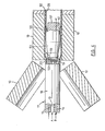
- Figure 5 shows a detail of a fourth die assembly which is identical in construction to the die assembly shown in Figure 1, the same reference numerals being used to denote corresponding parts.
- the essential difference between this embodiment of the invention and the first embodiment of the invention is that the mould blocks 10 have contoured interior surfaces appropriate to the moulding of corrugated tubing.
Landscapes
- Engineering & Computer Science (AREA)
- Mechanical Engineering (AREA)
- Manufacturing & Machinery (AREA)
- Extrusion Moulding Of Plastics Or The Like (AREA)
- Moulds For Moulding Plastics Or The Like (AREA)
- Processing And Handling Of Plastics And Other Materials For Molding In General (AREA)
- Blow-Moulding Or Thermoforming Of Plastics Or The Like (AREA)
- Shaping Of Tube Ends By Bending Or Straightening (AREA)
Priority Applications (1)
| Application Number | Priority Date | Filing Date | Title |
|---|---|---|---|
| AT81304028T ATE9294T1 (de) | 1980-09-12 | 1981-09-03 | Strangpresskopf-anordnung fuer thermoplastische schlaeuche. |
Applications Claiming Priority (2)
| Application Number | Priority Date | Filing Date | Title |
|---|---|---|---|
| US06/186,627 US4305703A (en) | 1980-09-12 | 1980-09-12 | Composite die assembly for use in the production of thermoplastic tubing |
| US186627 | 1988-04-27 |
Publications (2)
| Publication Number | Publication Date |
|---|---|
| EP0048112A1 true EP0048112A1 (de) | 1982-03-24 |
| EP0048112B1 EP0048112B1 (de) | 1984-09-12 |
Family
ID=22685681
Family Applications (1)
| Application Number | Title | Priority Date | Filing Date |
|---|---|---|---|
| EP81304028A Expired EP0048112B1 (de) | 1980-09-12 | 1981-09-03 | Strangpresskopf-Anordnung für thermoplastische Schläuche |
Country Status (6)
| Country | Link |
|---|---|
| US (1) | US4305703A (de) |
| EP (1) | EP0048112B1 (de) |
| JP (1) | JPS57142326A (de) |
| AT (1) | ATE9294T1 (de) |
| CA (1) | CA1166415A (de) |
| DE (1) | DE3166040D1 (de) |
Cited By (1)
| Publication number | Priority date | Publication date | Assignee | Title |
|---|---|---|---|---|
| DE4238605A1 (de) * | 1992-11-17 | 1994-05-19 | Rasmussen Gmbh | Flexible Fluidleitung |
Families Citing this family (32)
| Publication number | Priority date | Publication date | Assignee | Title |
|---|---|---|---|---|
| US4402898A (en) * | 1981-09-28 | 1983-09-06 | Hancor, Inc. | Coextrusion die assembly |
| CA1172813A (en) * | 1982-06-16 | 1984-08-21 | Lupke, Manfred A. A. | Apparatus for producing multi-walled thermoplastic tubing |
| US4655987A (en) * | 1982-10-12 | 1987-04-07 | Guillermo Zertuche | Method and apparatus for extruding tubular articles having several conduits |
| CA1187258A (en) * | 1982-12-02 | 1985-05-21 | Lupke, Manfred A. A. | Method and apparatus for forming a double walled thermoplastic tube with integral bells |
| SE449456B (sv) * | 1983-11-15 | 1987-05-04 | Uponor Ab | Forfarande och anordning for framstellning av ror varvid formbacksdelarna er delade i formstreckans lengsriktning |
| US5124109A (en) * | 1984-07-18 | 1992-06-23 | Contech Construction Products Inc. | Method for producing a double wall pipe |
| US4846660A (en) * | 1984-07-18 | 1989-07-11 | Contech Construction Products Inc. | Apparatus for producing double wall pipe |
| US4598457A (en) * | 1985-08-26 | 1986-07-08 | Allied Corporation | Method of constructing a brake pedal |
| US4770618A (en) * | 1986-01-15 | 1988-09-13 | Lupke Manfred Arno Alfred | Extrusion die for two-ply plastic tubing |
| FI77405C (fi) * | 1986-03-20 | 1989-03-10 | Uponor Nv | Foerfarande och anordning foer framstaellning av kamflaensroer. |
| US4936768A (en) * | 1986-03-25 | 1990-06-26 | Lupke Manfred Arno Alfred | Extrusion die for externally ribbed plastic tubing |
| US4712993A (en) * | 1986-03-25 | 1987-12-15 | Lupke Manfred Arno Alfred | Extrusion die for externally ribbed plastic tubing |
| US4723902A (en) * | 1986-08-21 | 1988-02-09 | Wheeling Stamping Company | Balanced flow extrusion crosshead and die assembly |
| US4789327B1 (en) * | 1988-02-25 | 2000-07-18 | Corma Inc | Adjustable pipe extrusion die with internal cooling |
| CA1308531C (en) * | 1988-10-11 | 1992-10-13 | Manfred A. A. Lupke | Extrusion die assembly |
| US5324557A (en) * | 1991-06-06 | 1994-06-28 | Lupke Manfred Arno Alfred | Multi-skin annularly ribbed tube |
| ATA53792A (de) * | 1992-03-17 | 1995-02-15 | Chemiefaser Lenzing Ag | Verfahren zur herstellung cellulosischer formkörper, vorrichtung zur durchführung des verfahrens sowie verwendung einer spinnvorrichtung |
| US5489201A (en) * | 1993-04-15 | 1996-02-06 | Cullom Machine Tool & Die, Inc. | Plastic tile corrugator and mold blocks |
| AT402738B (de) * | 1993-07-28 | 1997-08-25 | Chemiefaser Lenzing Ag | Spinndüse |
| JPH07171882A (ja) * | 1993-10-28 | 1995-07-11 | Tigers Polymer Corp | 可とう性ホースの製造方法および可とう性ホース |
| US5518036A (en) * | 1994-09-29 | 1996-05-21 | Phillips Petroleum Company | Multi-layer plastic pipe and method and apparatus for extrusion thereof |
| US5725814A (en) * | 1995-06-07 | 1998-03-10 | Harrel, Inc. | Extrusion of an article of varying content |
| US5695789A (en) * | 1995-06-07 | 1997-12-09 | Harrel, Inc. | Apparatus for extrusion of an article of varying content |
| DE29723138U1 (de) * | 1997-05-20 | 1998-08-06 | Lupke, Manfred Arno Alfred, Thornhill, Ontario | Vorrichtung zur Herstellung von Kunststoffrohren ohne Ausübung eines mechanischen Druckes auf die innere Rohrwandung |
| CA2459907C (en) * | 2001-09-10 | 2012-10-23 | Pirelli & C. S.P.A. | Extrusion method and apparatus for producing a cable |
| US20030080462A1 (en) * | 2001-10-25 | 2003-05-01 | Nordgren Douglas S. | Extrusion die with horizontal and vertical extrudate opening adjustment |
| US20040060609A1 (en) * | 2002-05-31 | 2004-04-01 | Fatato Francis B. | Monolayer foamed corrugated sleeve |
| JP4592351B2 (ja) * | 2004-08-10 | 2010-12-01 | 因幡電機産業株式会社 | 波形可撓管 |
| US8936460B2 (en) * | 2009-09-22 | 2015-01-20 | American Maplan Corporation | Extrusion head with high volume reservoir |
| JP7177844B2 (ja) | 2018-02-28 | 2022-11-24 | リュプケ、マンフレッド、エイ.エイ. | ダイヘッド及びダイツーリングのスパイダー、湾曲したスパイダーレグの材料の流れ制御 |
| AT522497B1 (de) * | 2019-02-14 | 2021-10-15 | Agru Kunststofftechnik Ges M B H | Verfahren zum Herstellen eines Rohres, sowie Vorrichtung zum Durchführen des Verfahrens |
| JP7687111B2 (ja) * | 2021-07-26 | 2025-06-03 | トヨタ自動車株式会社 | 管体の製造装置 |
Citations (6)
| Publication number | Priority date | Publication date | Assignee | Title |
|---|---|---|---|---|
| DE1028325B (de) * | 1954-11-13 | 1958-04-17 | Lissmann Alkor Werk | Verfahren und Einrichtung zur Herstellung von Schlauchfolien |
| US3538209A (en) * | 1967-02-27 | 1970-11-03 | Wilhelm Hegler | Method of producing plastic tubing having a corrugated outer wall |
| US3689192A (en) * | 1970-03-03 | 1972-09-05 | Windmoeller & Hoelscher | Manufacture of film from thermoplastic material that is blown by a blowhead |
| DE2333488A1 (de) * | 1972-07-03 | 1974-01-24 | Dayco Corp | Einstueckiger schlauch und einrichtung und verfahren zu seiner herstellung |
| US3976414A (en) * | 1974-03-22 | 1976-08-24 | Wilhelm Hegler | Apparatus for the production of double-walled synthetic plastic tubes having a transversely corrugated outer wall and a smooth inner wall |
| US3994644A (en) * | 1974-03-22 | 1976-11-30 | Wilhelm Hegler | Extruder head for extruding an outer tube or sheath about an inner tube or cable |
Family Cites Families (13)
| Publication number | Priority date | Publication date | Assignee | Title |
|---|---|---|---|---|
| US3024494A (en) * | 1958-07-21 | 1962-03-13 | Porter Co Inc H K | Plastic pipe extrusion head |
| DE1199971B (de) * | 1963-07-30 | 1965-09-02 | Lissmann Alkor Werk | Presskopf zur Herstellung eines mehrschichtigen Kunststoffschlauches |
| US3241503A (en) * | 1963-08-21 | 1966-03-22 | Schafer Leonhard | Concentric pastry die |
| DE1930987A1 (de) * | 1969-06-19 | 1970-12-23 | Barmag Barmer Maschf | Extrusionswerkzeug zum Herstellen von Mehrschichtblasfolien |
| US3743456A (en) * | 1971-08-20 | 1973-07-03 | Acme Hamilton Mfg Corp | Adjustable die heads for extruders and the like |
| US3981663A (en) * | 1973-09-10 | 1976-09-21 | Lupke Gerd Paul Heinrich | Apparatus for making high speed corrugated plastic tubing |
| US3994646A (en) * | 1974-01-25 | 1976-11-30 | Frankische Isolierrohr-Und Metallwaren Werke Gebr. Kirchner | Apparatus for producing double-walled tubes of plastic material |
| JPS51147556A (en) * | 1975-06-13 | 1976-12-17 | Toyo Soda Mfg Co Ltd | Multiilayer rotary circular die |
| US4047868A (en) * | 1975-08-12 | 1977-09-13 | Toppan Printing Co., Ltd. | Multilayer parison extrusion molding machine for blow molding |
| JPS5814294B2 (ja) * | 1976-04-26 | 1983-03-18 | 呉羽化学工業株式会社 | 合成樹脂複合管状体の成形方法及びダイ構造 |
| CA1083765A (en) * | 1976-12-01 | 1980-08-19 | Gerd P. H. Lupke | Apparatus for producing thermoplastic tubing |
| US4185954A (en) * | 1977-08-23 | 1980-01-29 | Kabushiki Kaisha Plastic Kogaku Kenkyusho | Die for extruding tubes composed of a plurality of layers |
| US4182603A (en) * | 1978-03-27 | 1980-01-08 | Egan Machinery Company | Multilayer tubular extrusion die |
-
1980
- 1980-09-12 US US06/186,627 patent/US4305703A/en not_active Expired - Lifetime
-
1981
- 1981-08-21 CA CA000384407A patent/CA1166415A/en not_active Expired
- 1981-09-03 DE DE8181304028T patent/DE3166040D1/de not_active Expired
- 1981-09-03 AT AT81304028T patent/ATE9294T1/de not_active IP Right Cessation
- 1981-09-03 EP EP81304028A patent/EP0048112B1/de not_active Expired
- 1981-09-11 JP JP56142559A patent/JPS57142326A/ja active Granted
Patent Citations (8)
| Publication number | Priority date | Publication date | Assignee | Title |
|---|---|---|---|---|
| DE1028325B (de) * | 1954-11-13 | 1958-04-17 | Lissmann Alkor Werk | Verfahren und Einrichtung zur Herstellung von Schlauchfolien |
| US3538209A (en) * | 1967-02-27 | 1970-11-03 | Wilhelm Hegler | Method of producing plastic tubing having a corrugated outer wall |
| US3689192A (en) * | 1970-03-03 | 1972-09-05 | Windmoeller & Hoelscher | Manufacture of film from thermoplastic material that is blown by a blowhead |
| DE2009914B2 (de) * | 1970-03-03 | 1973-05-30 | Windmoller & Holscher, 4540 Len gench | Folienblaskopf zur herstellung von kunststoff-schlauchfolien |
| DE2333488A1 (de) * | 1972-07-03 | 1974-01-24 | Dayco Corp | Einstueckiger schlauch und einrichtung und verfahren zu seiner herstellung |
| GB1431796A (en) * | 1972-07-03 | 1976-04-14 | Dayco Corp | Method for making a hose construction |
| US3976414A (en) * | 1974-03-22 | 1976-08-24 | Wilhelm Hegler | Apparatus for the production of double-walled synthetic plastic tubes having a transversely corrugated outer wall and a smooth inner wall |
| US3994644A (en) * | 1974-03-22 | 1976-11-30 | Wilhelm Hegler | Extruder head for extruding an outer tube or sheath about an inner tube or cable |
Cited By (1)
| Publication number | Priority date | Publication date | Assignee | Title |
|---|---|---|---|---|
| DE4238605A1 (de) * | 1992-11-17 | 1994-05-19 | Rasmussen Gmbh | Flexible Fluidleitung |
Also Published As
| Publication number | Publication date |
|---|---|
| US4305703A (en) | 1981-12-15 |
| EP0048112B1 (de) | 1984-09-12 |
| ATE9294T1 (de) | 1984-09-15 |
| CA1166415A (en) | 1984-05-01 |
| DE3166040D1 (en) | 1984-10-18 |
| JPH031140B2 (de) | 1991-01-09 |
| JPS57142326A (en) | 1982-09-03 |
Similar Documents
| Publication | Publication Date | Title |
|---|---|---|
| US4305703A (en) | Composite die assembly for use in the production of thermoplastic tubing | |
| KR900004432B1 (ko) | 2개의 층으로된 파형수지관의 압출기 | |
| CN100526048C (zh) | 连续制造带管接头的复壁管的方法、复壁管和实施该方法和制造该复壁管的装置 | |
| CA1172813A (en) | Apparatus for producing multi-walled thermoplastic tubing | |
| US3677676A (en) | Apparatus for forming plastic tubing having a smooth inner wall and a corrugated outer wall | |
| US4906496A (en) | Double-walled tube assembly | |
| EP2261003B1 (de) | Extrudierkopf zum extrudieren eines rohrförmigen Produkts | |
| US4832589A (en) | Head for the circular coextrusion of a plurality of thermo-plastic material layers | |
| CA1309564C (en) | Adjustable pipe extrusion die with internal cooling | |
| KR900001936B1 (ko) | 외부에 산과 골이 나선상으로 형성된 플라스틱관용 압출다이 | |
| US4995800A (en) | Extrusion die assembly | |
| US3966377A (en) | Blowhead for tubular film | |
| EP0483153B2 (de) | Verfahren zum formen von rohren unter verwendung von pneumatischem unter- und überdruck an der oberfläche des kühldorns | |
| US3146495A (en) | Seamless plastic tubing extrusion molding machine | |
| CN110450371A (zh) | 一种波纹机多层机头 | |
| EP0381938B1 (de) | Kühldorne für Vorrichtungen zur Herstellung thermoplastischer Rohre | |
| CN101444960A (zh) | 连续制造带管接头的复壁管的装置 | |
| US4936768A (en) | Extrusion die for externally ribbed plastic tubing | |
| BR8601635A (pt) | Processo e equipamento para a producao de tubos de paredes duplas | |
| US2788543A (en) | Apparatus for producing plastic pipe | |
| US20040131716A1 (en) | Device for producing double-walled corrugated pipes | |
| US1933212A (en) | Tubing machine | |
| US3533134A (en) | Apparatus for extruding tubes and pipes | |
| JP3222890B2 (ja) | 交換可能な押出しノズル付押出しダイ | |
| KR950005723B1 (ko) | 합성수지재 2중관의 성형방법 및 장치 |
Legal Events
| Date | Code | Title | Description |
|---|---|---|---|
| PUAI | Public reference made under article 153(3) epc to a published international application that has entered the european phase |
Free format text: ORIGINAL CODE: 0009012 |
|
| AK | Designated contracting states |
Designated state(s): AT BE CH DE FR GB IT LU NL SE |
|
| 17P | Request for examination filed |
Effective date: 19820318 |
|
| ITF | It: translation for a ep patent filed | ||
| GRAA | (expected) grant |
Free format text: ORIGINAL CODE: 0009210 |
|
| AK | Designated contracting states |
Designated state(s): AT BE CH DE FR GB IT LI LU NL SE |
|
| PG25 | Lapsed in a contracting state [announced via postgrant information from national office to epo] |
Ref country code: SE Effective date: 19840912 Ref country code: NL Effective date: 19840912 Ref country code: LI Effective date: 19840912 Ref country code: CH Effective date: 19840912 Ref country code: BE Effective date: 19840912 Ref country code: AT Effective date: 19840912 |
|
| REF | Corresponds to: |
Ref document number: 9294 Country of ref document: AT Date of ref document: 19840915 Kind code of ref document: T |
|
| REF | Corresponds to: |
Ref document number: 3166040 Country of ref document: DE Date of ref document: 19841018 |
|
| ET | Fr: translation filed | ||
| REG | Reference to a national code |
Ref country code: CH Ref legal event code: PL |
|
| NLV1 | Nl: lapsed or annulled due to failure to fulfill the requirements of art. 29p and 29m of the patents act | ||
| PLBE | No opposition filed within time limit |
Free format text: ORIGINAL CODE: 0009261 |
|
| STAA | Information on the status of an ep patent application or granted ep patent |
Free format text: STATUS: NO OPPOSITION FILED WITHIN TIME LIMIT |
|
| 26N | No opposition filed | ||
| PG25 | Lapsed in a contracting state [announced via postgrant information from national office to epo] |
Ref country code: LU Free format text: LAPSE BECAUSE OF NON-PAYMENT OF DUE FEES Effective date: 19850930 |
|
| PGFP | Annual fee paid to national office [announced via postgrant information from national office to epo] |
Ref country code: FR Payment date: 19890825 Year of fee payment: 9 |
|
| ITTA | It: last paid annual fee | ||
| PGFP | Annual fee paid to national office [announced via postgrant information from national office to epo] |
Ref country code: DE Payment date: 19891026 Year of fee payment: 9 |
|
| PG25 | Lapsed in a contracting state [announced via postgrant information from national office to epo] |
Ref country code: FR Effective date: 19910530 |
|
| PG25 | Lapsed in a contracting state [announced via postgrant information from national office to epo] |
Ref country code: DE Effective date: 19910601 |
|
| REG | Reference to a national code |
Ref country code: FR Ref legal event code: ST |
|
| PGFP | Annual fee paid to national office [announced via postgrant information from national office to epo] |
Ref country code: GB Payment date: 19940902 Year of fee payment: 14 |
|
| PG25 | Lapsed in a contracting state [announced via postgrant information from national office to epo] |
Ref country code: GB Effective date: 19950903 |
|
| GBPC | Gb: european patent ceased through non-payment of renewal fee |
Effective date: 19950903 |