EP0048164B1 - Chirurgische Entleerungsvorrichtung - Google Patents
Chirurgische Entleerungsvorrichtung Download PDFInfo
- Publication number
- EP0048164B1 EP0048164B1 EP81304237A EP81304237A EP0048164B1 EP 0048164 B1 EP0048164 B1 EP 0048164B1 EP 81304237 A EP81304237 A EP 81304237A EP 81304237 A EP81304237 A EP 81304237A EP 0048164 B1 EP0048164 B1 EP 0048164B1
- Authority
- EP
- European Patent Office
- Prior art keywords
- spring
- reservoir
- force
- articulated
- plates
- Prior art date
- Legal status (The legal status is an assumption and is not a legal conclusion. Google has not performed a legal analysis and makes no representation as to the accuracy of the status listed.)
- Expired
Links
- 239000012530 fluid Substances 0.000 claims description 46
- 230000007423 decrease Effects 0.000 claims description 17
- 230000006835 compression Effects 0.000 claims description 11
- 238000007906 compression Methods 0.000 claims description 11
- 230000003247 decreasing effect Effects 0.000 claims description 9
- 239000012528 membrane Substances 0.000 claims description 8
- 229920003023 plastic Polymers 0.000 claims description 4
- 239000004033 plastic Substances 0.000 claims description 4
- 230000009471 action Effects 0.000 claims description 2
- 239000003570 air Substances 0.000 description 11
- 239000000463 material Substances 0.000 description 10
- 208000027418 Wounds and injury Diseases 0.000 description 6
- 230000007246 mechanism Effects 0.000 description 6
- 238000005452 bending Methods 0.000 description 5
- 230000001954 sterilising effect Effects 0.000 description 5
- 238000004659 sterilization and disinfection Methods 0.000 description 5
- 230000003993 interaction Effects 0.000 description 4
- 230000036961 partial effect Effects 0.000 description 4
- 230000000717 retained effect Effects 0.000 description 4
- 238000003860 storage Methods 0.000 description 4
- 238000013461 design Methods 0.000 description 3
- 238000000034 method Methods 0.000 description 3
- 230000008859 change Effects 0.000 description 2
- 230000000694 effects Effects 0.000 description 2
- 230000036512 infertility Effects 0.000 description 2
- 230000003902 lesion Effects 0.000 description 2
- 238000012423 maintenance Methods 0.000 description 2
- 230000002441 reversible effect Effects 0.000 description 2
- 239000013589 supplement Substances 0.000 description 2
- 238000012360 testing method Methods 0.000 description 2
- QNRATNLHPGXHMA-XZHTYLCXSA-N (r)-(6-ethoxyquinolin-4-yl)-[(2s,4s,5r)-5-ethyl-1-azabicyclo[2.2.2]octan-2-yl]methanol;hydrochloride Chemical compound Cl.C([C@H]([C@H](C1)CC)C2)CN1[C@@H]2[C@H](O)C1=CC=NC2=CC=C(OCC)C=C21 QNRATNLHPGXHMA-XZHTYLCXSA-N 0.000 description 1
- 206010014405 Electrocution Diseases 0.000 description 1
- 239000004743 Polypropylene Substances 0.000 description 1
- 239000012080 ambient air Substances 0.000 description 1
- 238000013459 approach Methods 0.000 description 1
- 230000008901 benefit Effects 0.000 description 1
- 238000010276 construction Methods 0.000 description 1
- 238000005520 cutting process Methods 0.000 description 1
- 210000003811 finger Anatomy 0.000 description 1
- 229920002457 flexible plastic Polymers 0.000 description 1
- 231100001261 hazardous Toxicity 0.000 description 1
- 230000035876 healing Effects 0.000 description 1
- 208000015181 infectious disease Diseases 0.000 description 1
- 238000003780 insertion Methods 0.000 description 1
- 230000037431 insertion Effects 0.000 description 1
- 238000012804 iterative process Methods 0.000 description 1
- 238000004519 manufacturing process Methods 0.000 description 1
- 230000037361 pathway Effects 0.000 description 1
- -1 polypropylene Polymers 0.000 description 1
- 229920001155 polypropylene Polymers 0.000 description 1
- 229920000915 polyvinyl chloride Polymers 0.000 description 1
- 239000004800 polyvinyl chloride Substances 0.000 description 1
- 230000007425 progressive decline Effects 0.000 description 1
- 230000009467 reduction Effects 0.000 description 1
- 230000002829 reductive effect Effects 0.000 description 1
- 230000004044 response Effects 0.000 description 1
- 230000035939 shock Effects 0.000 description 1
- 238000004513 sizing Methods 0.000 description 1
- 239000007787 solid Substances 0.000 description 1
- 238000001356 surgical procedure Methods 0.000 description 1
- 210000003813 thumb Anatomy 0.000 description 1
- 238000004804 winding Methods 0.000 description 1
Images

Classifications
-
- A—HUMAN NECESSITIES
- A61—MEDICAL OR VETERINARY SCIENCE; HYGIENE
- A61M—DEVICES FOR INTRODUCING MEDIA INTO, OR ONTO, THE BODY; DEVICES FOR TRANSDUCING BODY MEDIA OR FOR TAKING MEDIA FROM THE BODY; DEVICES FOR PRODUCING OR ENDING SLEEP OR STUPOR
- A61M1/00—Suction or pumping devices for medical purposes; Devices for carrying-off, for treatment of, or for carrying-over, body-liquids; Drainage systems
- A61M1/64—Containers with integrated suction means
- A61M1/68—Containers incorporating a flexible member creating suction
-
- A—HUMAN NECESSITIES
- A61—MEDICAL OR VETERINARY SCIENCE; HYGIENE
- A61M—DEVICES FOR INTRODUCING MEDIA INTO, OR ONTO, THE BODY; DEVICES FOR TRANSDUCING BODY MEDIA OR FOR TAKING MEDIA FROM THE BODY; DEVICES FOR PRODUCING OR ENDING SLEEP OR STUPOR
- A61M1/00—Suction or pumping devices for medical purposes; Devices for carrying-off, for treatment of, or for carrying-over, body-liquids; Drainage systems
- A61M1/60—Containers for suction drainage, adapted to be used with an external suction source
- A61M1/63—Containers for suction drainage, adapted to be used with an external suction source with means for emptying the suction container, e.g. by interrupting suction
Definitions
- This invention relates to portable surgical evacuation devices which are disposable and self-contained.
- evacuators typically comprise collapsible reservoirs biased with springs or weights which bias them to open after being manually compressed. Since these devices are self-contained and portable, the patient may be easily moved without disconnecting him from the device. However, many of these prior art devices are not capable of maintaining a substantially constant vacuum over their entire filling range. Constant vacuum pressure is desirable, since this permits uniform removal of fluid from the patient. If the vacuum is too high, lesions may be caused by sucking delicate tissue into or against the drainage tube. Conversely, if the vacuum is too low, fluid will accumulate and the device will be ineffective. Thus a substantially constant pressure fluid evacuator is considered highly advantageous.
- the Abramson device consists of a reservoir comprising a flexible plastics bag, first and second planar inserts within the bag for supporting two opposed side walls of the bag and a pair of leaf springs disposed between the two inserts, biasing them apart to expand the bag and create a vacuum therein, the force provided by the springs on the inserts decreasing as the reservoir formed by the bag expands.
- West German Specification DE 2 500 391 describes a fluid evacuator comprising a flexible reservoir which is squeezed between two rigid plates by a compression spring so as to change the shape of the reservoir from an initial rhombic configuration to a square configuration and to thereby increase the internal volume of the reservoir to create a vacuum therein.
- the effective wall area of the reservoir over which the spring force acts increases as the spring force decreases.
- this device is again incapable of providing the necessary constancy of suction level desirable in practice.
- a surgical evacuation device which comprises a compressible reservoir which expands in use by spring action to draw fluid from a wound. into the reservoir, the reservoir being formed by a flexible membrane, first and second walls disposed therewithin for supporting the membrane in the expanded state of the reservoir, and a spring disposed between the walls and biasing them apart to expand the reservoir and create a vacuum therein and whose force on the walls decreases as the reservoir expands.
- One object of the present invention is to provide a device of this type which can alleviate these problems of the prior art by providing a reservoir which may draw a substantially constant negative pressure.
- each of the first and second walls is itself articulated and they co-operate to form an articulated structure for supporting the membrane, the shape of the articulated structure varying as the reservoir expands and defining a shape for the reservoir such as to at least partially offset the decreasing force of the spring to reduce changes in reservoir vacuum, and wherein the articulated walls are sufficiently rigid that, other than for the purposes of articulation, they remain undeformed by the spring in use.
- the variation in the shape of the structure decreases the effective wall area acted upon by the force of the spring.
- the variation permits atmospheric forces on the articulated walls to provide a correspondingly varying supplementary force to assist the spring in biasing the walls apart, the supplementary force increasing as the reservoir expands to co-operate with the force of the spring to reduce changes in vacuum as the reservoir expands.
- the membrane which seals the area between the articulated walls from the atmosphere, comprises a plastics bag containing and sized to the articulative structure.
- the articulated walls comprise a pair of congruent, superimposed, hinged plates, each plate comprising a generally square or rectangular central member hingeably connected at opposite edges between wing members, each wing member having a generally isosceles trapezoidal shape with its longest side remote from the central member, two of said longest sides being hingeably connected to form the articulative structure.
- the present invention thus provides a preferably pre-evacuated flexible reservoir which houses an articulated, spring biased, skeletal mechanism.
- the skeletal mechanism and the . reservoir co-operate to permit the reservoir to draw a vacuum at a substantially constant negative pressure.
- An internal latch is preferably included within the skeletal mechanism to maintain the reservoir in a compressed, evacuated condition prior to use.
- the skeletal mechanism comprises a substantially conical helical spring, interposed between two articulated walls or plates.
- the spring biases the plates in opposite directions.
- Each of the plates includes a generally square or rectangular central member that is connected on opposite sides to respective wing members by integral hinges.
- Each of the two wing members is generally shaped as an isosceles trapezoid, and one of the two wing members has a pair of triangular notches.
- the central member and two wing members of each plate are of the same dimensions to permit the plates of the congruent.
- the plates are retained in a congruent position by means of one or more hinges on the ends of the unnotched wing members of the respective plates. Since the hinges are at the end of the unnotched wing members, they do not prevent the central members and two wing members from privoting relative to each other as the reservoir fills.
- the central members each have a spring cup to permit the spring to be retained therebetween.
- the individual coils of the conical biasing spring compress to nest within one another and within the recesses of the spring cups.
- a latch is included within each of the respective spring cups to retain the spring, the skeletal mechanism, and the reservoir in a compressed state.
- the plates, with the spring compressed therebetween, are sealed in the reservoir which comprises a rectangular plastic bag.
- the bag is limp or flexible, is sized to fit the overall length and width of the plates, and is stretched to ensure that the plates fit snugly therein. Since the latch holds the spring in a compressed state, the plates lie flat against one another, thereby permitting the device to be manufactured and shipped in a thin, compact, and pre-compressed state. This significantly reduces the cost of sterilization, shipment, and storage. Further, such precompression eliminates the task of evacuating the device at its point of use by manually compressing it.
- a vacuum on the reservoir after it is compressed and latched, but prior to shipment to the consumer.
- This is a convenient method of removing residual pockets of air from the reservoir.
- vacuum permits atmospheric pressure to exert force against the exterior surfaces of the two plates. This assists the latch in maintaining the device in a compressed state, and thereby reduces stress forces on the latch.
- the device may be stored in its pre-evacuated state for long periods of time without deformation of the latch mechanism.
- the vacuum effectively immobilizes the latch and thereby reduces the risk of accidental or inadvertent disengagement.
- the reservoir includes a drain tube and a fluid collection tube which pass through the reservoir wall into the triangular notches, respectively, of the notched wing members. At the points where these tubes pass through the reservoir, they are sealed to the reservoir. These tubes extend wall into the reservoir to reduce the likelihood that the reservoir wall might interfere with the flow of fluid.
- the fluid collection tube includes a check valve to prevent reverse flow of fluid from the reservoir to the patient.
- the drain tube includes perforations along its extension into the reservoir to assure that the reservoir will be completely drained even if the end of the drain tube is blocked. A plug or stopper is provided to seal the drain tube when not in use.
- the end of the fluid collection tube outside the reservoir is terminated in a Y-fitting to permit the fluid evacuation device to be connected to one or two catheters.
- the Y-fitting is normally sealed to maintain the previously discussed vacuum in the reservoir.
- a nurse or medical assistant will remove this seal.
- a small amount of air is permitted to enter the reservoir through the unsealed Y-fitting.
- Such air will not destroy the sterility of the device, since the Y-fitting seal is typically broken in an operating room environment.
- the amount of air entering the reservoir is so small that it will have little, if any, effect on the fluid capacity of the device. However, the amount of air is sufficient to break the vacuum, and thereby permit the latch to function.
- the surgical evacuator is activated simply by bending the unnotched wing members relative to the central members. Such bending causes the central plates to slide relative to one another, and thereby disengages the latch. This releases the conical spring, and thus, the spring will force the plates apart. As the distance between the plates increases, the volume of the reservoir will concommitantly increase. However, since the reservoir is sealed from the atmosphere, the volume of the reservoir cannot increase unless it draws fluid from the catheter. Thus, as the plates are forced apart, a suction or vacuum will be created to draw fluid into the reservoir.
- the nominal value of reservoir vacuum for fluid evacuation purposes is typically 6895 Pa. It was a primary design consideration in the present invention to limit deviations in vacuum to less than 20% from the nominal value in the belief that such limitation will virtually eliminate the risk that the vacuum will cause lesions by sucking tissue into the catheter's drain tube. Further, it is believed that such limitation in vacuum pressure will ensure that the device will have sufficient suction to prevent excessive fluid buildup. Accordingly, the present invention is designed to limit deviations in vacuum to ⁇ 20% throughout its operating range. This is accomplished both by the design of the spring and the unique geometry of the plates. As discussed above, the spring is conical to permit it, when compressed, to nest in the spring cups. Thus, the diameter of the spring coils will vary from one end to the other.
- the spring constant i.e., the slope of the force versus distance curve
- a conical spring typically has a non linear spring constant.
- the spring constant varies directly with the pitch of the spring coils.
- the inherent non-linearity of the spring constant of a conical spring may be compensated for by varying the pitch of the spring coils. Accordingly, by increasing the pitch of the coils as the coil diameter increases, the spring of the present invention is formed to have an essentially linear spring constant.
- the force exerted by the coils of a conical spring having a linear spring constant is directly proportional to the amount that they are compressed.
- the force exerted by such spring will progressively, linearly decrease as the distance between the plates increases.
- Such decrease in the force exerted by the spring is compensated for by the unique geometry of the plates.
- the plates are articulated by hinging each pair of wing members to its respective central member.
- their respective pair of wing members will pivot inward.
- Such inward movement of the wing members permits the spring to exert force over a progressively smaller effective plate area. Since both the spring force and this effective plate area decrease as the plates separate, the force per unit of area remains more nearly constant.
- such articulation of the plates compensates for the progressive decrease in spring force.
- the reservoir is sized to fit snugly around the plates.
- the vacuum created by the expanding volume of the reservoir will force the reservoir wall inward against the articulated plates.
- the central members lie in the horizontal plane
- the horizontal component of the force exerted by the reservoir wall on the wing members will increase and the vertical component will decrease, as the wing members pivot inward at progressively increasing angles with respect to the central members.
- This horizontal force on the wing members will drive the wing members inward.
- the wing members are integrally hinged.to the central members, the wing members will wedge against the central members to force them apart.
- the unique geometry presently proposed permits the spring force per unit of effective area to remain substantially constant, and thereby limits vacuum pressure deviations to ⁇ 20% to permit maintenance of a substantially constant negative pressure throughout the entire filling range of the device.
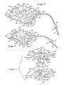
- the illustrated embodiment of the present invention comprises a pair of congruent, articulated plates 10a and 10b with a conical helical spring 14 interposed therebetween.
- Each of the plates 10a, 10b includes a respective square or rectangular central member 16a, 16b which is connected by integrally formed hinges 17a, 17b to respective trapezoidal wing members 18a, 18b and 20a, 20b.
- the trapezoidal wing members 18, 20 are disposed on opposite sides of the central members 16 and have an isosceles configuration, with the shorter of their trapezoidal bases being hinged to the central member 16.
- the plates 10 are shaped substantially as rectangles with trapezoidal cut- outs 21, 22 (Fig. 2) on opposite sides.
- the wing members 20a and 20b include a pair of essentially triangular notches 23a, 24a and 23b 24b, respectively, while the wing members 18a and 18b are not notched.
- the wing member 18a includes a pair of upstanding hinge hooks 26 which are sized to be received by a pair of slots 28 in the wing member 18b.
- the plates 10a and 10b include respective inverted spring cups or bosses 32a and 32b and respective recessed spring cups 34a and 34b.
- the spring boss 32 is sized to retain the small coil diameter end of the conical spring 14 while the spring cup 34 is sized to retain the large coil diameter end of the conical spring 14.
- Each of the plates 10 has both an inner spring boss 32 and an outer spring cup 34. Thus, either of the plates 10 may receive either end of the spring 14.
- the plates 10a, 10b are first hinged together, by inverting the plate 10a, inserting the hinge hooks 26 into the slots 28, and then rotating the plate 10a about the hooks 26. This assembly operation results in a congruent positioning of the plates 10, with a hinged connection therebetween at 30 ( Figure 2).
- the spring 14 is next compressed between the spring cups 32, 34 of the plates 10.
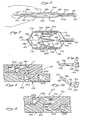
- the spring cups and bosses 32a, 34a and 32b, 34b form recesses 38a and 38b, respectively, in the plates 10a and 10b, respectively, to permit the fully compressed spring 14 to nest therein, and thereby permit the plates 10 to lie flat against each other with virtually no space therebetween (Figure 3).
- a latch member or hook 36b which protrudes from the interior face of the plate 10b, is provided within the spring boss 32b.
- the plate 10a has a similarly disposed latch member or hook 36a oriented 180 degrees with respect to the latch hook 36b. These latch hooks 36 form a latch 35 which retains the spring 14 in a compressed condition.
- the plates 10 with the compressed spring 14 retained therebetween are sealed in a rectangular membranous reservoir or plastic bag 40.
- the reservoir 40 is sized to fit the overall dimensions of the compressed plates 10. Further, the reservoir 40 is stretched in a direction shown by the arrow 41 to ensure that the bag fits snugly around the plates 10. Since the plates 10 are not solid rectangles because of the trapezoidal cut-outs 21, 22, the plates 10, therefore, will not contact the entire surface of the rectangular reservoir 40. As will be understood more fully below, the trapezoidal cut-outs of the plates 10 are included to permit the reservoir 40 to expand in volume as the device draws fluid from the patient.
- a fluid collection tube 42 and drain tube 43 are connected to the reservoir 40. Both of the tubes 42, 43 are sealed to the reservoir 40 at the point where they pass through the reservoir wall into the triangular notches 23, 24, respectively, of the wing members 20. These tubes 42, 43 extend well into the reservoir to reduce the likelihood that the reservoir wall will interfere with the flow of fluid.
- a check valve 44 is included on the end of the fluid collection tube 42 within the reservoir 40 to prevent reverse flow of fluid from the reservoir 40 to the patient.
- the drain tube 43 includes perforations 45 ( Figure 7) along its extension into the reservoir 40 to permit the reservoir 40 to be completely drained even if the end of the tube 43 is blocked.
- a plug or stopper 47 seals the drain tube when not in use.
- the reservoir 40 also includes a pair of flanges 48 to permit the reservoir to be attached to the patient by a strap (not shown).
- the end of the fluid collection tube 42 is terminated in a Y-fitting 50 having two catheter connections 51 to permit it to be connected to one or two wound drain catheters 52.
- the Y-fitting 50 is normally sealed to prevent ambient air from entering the reservoir 40. However, just prior to connecting the catheter 52, a nurse or medical assistant will remove this seal, typically by cutting the end of the catheter connector 51.
- the device may be precompressed by the manufacturer prior to shipment. As previously mentioned, the latch 35 retains the device in a precompressed state. However, it is preferable to also draw a vacuum on the reservoir 40 prior to shipment to completely evacuate any residual air contained in the reservoir 40. This vacuum permits atmospheric pressure to exert force on the walls of the reservoir 40 and thereby assists the latch 35 in maintaining the plates 10 in a precompressed state. Thus, stress forces on the latch hooks 36 are reduced and therefore the device may be stored in its pre-evacuated, pre- compressed state for substantial periods of time without deformation of the latch 35. Such precompression by the manufacturer also permits the device to be very compact, since the thickness of the device, when compressed, is equal to the combined thickness of the plates 10, typically about 9.5 mm.
- the vacuum prevents relative movement of the latch hooks 36 and thereby reduces the risk of accidental or inadvertent disengagement of the latch 35.
- the vacuum in order to disengage the latch 35, the vacuum must be broken. This is typically accomplished by breaking the previously described seal on the catheter connector 51 of the Y-fitting 50, thereby permitting a small amount of air to enter the reservoir 40. Since the seal is typically broken in an operating room environment, the sterility of the device will not be affected. Further, the quantity of air entering the reservoir is so small that its effect on the fluid capacity of the reservoir is insignificant. However, the quantity of air is sufficient to break the vacuum and thus permit the latch 35 to function.
- the latch 35 is comprised of latch hooks 36a and 36b, which extend from the interior of the plates 10a and 10b, respectively.
- the plates 10a and 10b have respective cavities 54a and 54b which receive the latch hooks 36b and 36a, respectively.
- the latch hooks 36a and 36b have respective hooking surfaces 56a and 56b which engage each other to hold the plates 10 against one another, as shown in Figure 4. These hooking surfaces 56 are inclined slightly relative to their respective plates 10 to inhibit them from sliding relative to each other, and thereby disengaging.
- the latches 35 may be disengaged by grasping the plates 10 between the fingers and thumb (shown in phantom) and bending the wing plates 18 upward with respect to the central plate 16. Such disengagement of the latch 35 is accomplished by forming the hinges 17 as semicircular slots which are disposed to face each other to form a cylindrical opening, as shown in Figure 3a. Referring to Figure 3b, as the wing members 18 pivot upward relative to their respective central members 16, the width of the slot forming the hinge 17a will decrease and the width of the slot forming the hinge 17a will concommitantly increase. Since the ends of the wing members 18 are connected together by the hinge 30, they will necessarily remain in a congruent position.
- the central members 16 will slide relative to each other. Since the latch hooks 36a and 36b are attached to the central members 16a and 16b, respectively, they will also slide relative to each other. Such sliding is sufficient to change the position of the latch hooks 36 from that shown in Figure 4 to that shown in Figure 5, and thus permit the hooking surfaces 56 to disengage. Therefore, the latch 35 may be disengaged simply by bending the wing members 18 relative to the central members 16. Such disengagement permits the conical spring to separate the plates 10 and thereby enables the device to draw fluid into the reservoir 40.
- the device may, if desired, be drained, compressed, and reused. This is accomplished by removing the drain plug 46, emptying the reservoir 40 by manually pushing the plates 10 against one another to compress the spring 14, and reinserting the drain plug 46.
- the latch 35 is adapted to re-engage when the spring 14 is fully compressed. This is accomplished by providing respective closing cam surfaces 58a, 58b and biasing cam surfaces 60a, 60b on the latch hooks 36a, 36b.
- the closing cam surfaces 58 are inclined relative to their respective central members 16, and co-operate to force the biasing cam surfaces 60a, 60b against respective resilient biasing tabs 64b and 64a.
- tabs 64a and 64b protrude from the respective cavities 54a and 54b of the respective plates 10a and 10b.
- their biasing cam surfaces 60a, 60b will bend the tabs 64b and 64a, respectively, in opposite directions, as shown in Figure 5.
- the resiliency of the tabs 58b and 58a will urge the hooking surfaces 56a and 56b towards each other to force them to engage, as shown in Figure 4.
- the biasing tabs 64 co-operate -with the latch hooks 36 to engage the latch 35 and thereby retain the spring 14 between the plates 10.
- the reservoir 40 When the latch 35 is disengaged, the compressed conical spring 14 will exert force on the central members 16 to force the plates 10 apart. Since the reservoir 40 is sealed from the atmosphere, such force creates a vacuum which draws fluid from the patient into the reservoir 40.
- the reservoir 40 will form side walls 68, 69 ( Figure 6) which conform to the trapezoidal cutouts 21, 22, respectively.
- the wall 69 is on the opposite side of the reservoir 40 from the wall 68. Since the reservoir 40 is stretched across the cut-outs 21, 22 in the direction indicated by the arrow 41, the reservoir walls 68, 69 will not be sucked between the plates 10, but rather will remain more or less perpendicular to the plates 10 as the reservoir 40 fills with fluid. This prevents any sudden changes in reservoir vacuum and permits the reservoir 40 to gradually expand in volume as the plates 10 separate.
- the reservoir 40 will have a defined, gradually changing, shape throughout its filling range.
- the spring 14 and the unique geometry of the plates 10 co-operate to permit the reservoir 40 to draw a substantially constant vacuum through its entire filling range.
- substantially constant means that the vacuum level does not fluctuate by more than 20%.
- Such co-operation may be more fully understood through reference to Figures 8, 9, and 10.
- Figure 8 it is well known that the force of a compression spring varies inversely to the distance it expands from a fully compressed state. Thus, when a spring is fully compressed, its force is at a maximum, and when it fully relaxes, its force is zero. This relationship is defined by the expression: where F is the force, A is the force at full compression, K is a constant, and X is the distance the spring relaxes from full compression.
- the constant K is typically referred to as the spring constant, and it defines the slope of the curve 70. It is apparent that, if it were possible to obtain a spring with a spring constant of zero, as indicated by the curve 72, the force exerted by the spring would always be a constant value. Such a spring would make the design of a constant vacuum fluid evacuator a relatively simple matter. For example, it is apparent that a spring with a zero spring constant interposed between two plates connected by bellows could be made to achieve the desired constant vacuum result. Unfortunately, however, a spring having a spring constant of zero would be infinitely long, since the spring, in order to maintain constant force, could never be permitted to fully relax. Thus, as a practical matter, a compromise must be drawn between the spring constant and the length of the spring.
- the unique plate geometry of the present invention permits such compromise. Specifically, the plate geometry compensates for the decreasing spring force as the spring 14 expands from a fully compressed state and thereby permits maintenance of a substantially constant pressure within the reservoir 40. It will be recalled that each of the plates 10 is articulated by hinging the wing members 18, 20 to their respective central members 16. Comparing Figures 2 and 3 with Figures 6 and 7, it can be seen that, as the plates 10 are forced apart by the spring 14, the wing members 18, 20 pivot inward with respect to the central members 16. This permits the effective plate area over which the spring force is applied to concommitantly decrease. Thus, the effective plate area decreases as the spring force decreases, and therefore, the force per unit of effective area remains more nearly constant. Since the vacuum within the reservoir 40 is proportional to the force per unit area applied to the plates 10, the vacuum will also be more nearly constant.
- the geometry of the plates 10 also supplements the spring force as the wing members 18, 20 pivot inward. This may be understood more fully by comparing the position of the wing members 18, 20 with respect to the central members 16, shown in Figure 3, with that shown in Figure 7. Referring initially to Figure 3, when the spring 14 is fully compressed, the wing members 18, 20 lie in the same horizontal plate as the central members 15. Thus, the forces generated by the spring 14 between the plates 10 and the opposing forces created by atmospheric pressure will both be directed vertically. However, as the wing plates 18, 20 pivot inward, as shown in Figure 7, it is apparent that the direction of the opposing atmospheric forces applied to the wing members 18, 20 will incline from the vertical toward the horizontal.
- the forces on the wing members 18, 20 will have a decreasing vertical component and an increasing horizontal component, as they pivot inward at progressively increasing angles with respect to the central members 16. Such horizontal component will drive the wing members 18, 20 inward. Since the wing members 18, 20 are connected to their respective central members 16 by the hinges 17, the inward movement of the wing members 18, 20 will result in a force which will wedge the central members apart. Thus, the spring force is supplemented by such horizontal forces on the wing members 18, 20.
- the reservoir 40 also interacts with the wing members 18, 20 to supplement the horizontal component force, described above, to drive the wing members 18, 20 inward and the central members apart. It will be recalled that the reservoir is stretched between the ends of the wing members 18, 20, and across the trapezoidal cut-outs 21, 22 to permit the reservoir side walls 68, 69 ( Figure 6) to remain more or less perpen- dicularto the central members 16 as the plates 10 spread apart. Thus, atmospheric pressure will exert force against such perpendicular reservoir walls 68, 69. This will pull the ends of the wing members 18, 20 toward each other and thereby provide a supplementary force which assists in driving the wing members 18, 20 inward. In addition, since the reservoir 40, as previously mentioned is stretched between the ends of the wing members 18, 20, such stretching will provide a further supplementary force to pivot the wing members 18, 20 inward relative to the central members 16.
- the unique geometry of the plates 10 provides compensation for the decrease in spring force as the plates 10 spread apart, and thereby permits the negative pressure within the reservoir 40 to remain substantially constant (i.e., within 20%) throughout the entire filling range.
- plate geometry may be defined by the terms listed below:
- the distance between the central members 16 may be defined by the expression: where X R is the distance between the central members 16, H w is the trapezoidal height of one of the wing members 18, 20, and theta is one-half of the angle formed by the wing member 18a with the wing member 18b or the wing member 20a with the wing member 20b.
- H w is a constant, this expression defines distance between the central members 16 as a function of theta.
- a graph of the spring force necessary to achieve a constant vacuum versus the distance between the central members 16 may be developed.
- the trapezoidal cut-outs 21, 22 formed by the central members 16 and wing members 18 and 20 of the respective plates 10 are sized to limit the maximum volume of the reservoir 40 to a value which limits the maximum distance between the central members 16 to the equivalent of 45 degrees of the angle theta.
- Such maximum distance which is also equal to the maximum height of the side walls 68, 69 ( Figure 6), may be calculated by using equation (7), discussed in reference to Figure 9, and substituting 45 degrees for theta.
- the dimension 80 of the cut-outs 21, 22 is one-half of the distance between the members 16 when theta is 45 degrees, or one-half of 1.414H w , such dimension, therefore, is equal to .707 H w , where H w ( Figure 9) is the trapezoidal height of one of the wing members 18, 20.
- H w Figure 9 is the trapezoidal height of one of the wing members 18, 20.
- the curve 74 of Figure 10 may be approximated by a spring having a linear force versus distance relationship.
- the spring should preferably be under full compression when theta equals zero degrees. Since the plates 10 lie flat against one another when theta equals zero degrees, the spring, therefore, should be conical to permit it to be compressed flat therebetween.
- the strength of a spring coil is inversely proportional to its diameter. The coils of a conical spring, therefore, typically vary in strength, since their diameters necessarily vary. Thus, upon expansion, the coils become progressively active, rather than simultaneously active, and the force versus distance relationship of the spring is consequently nonlinear. Therefore, a typical conical spring is incapable of providing the linear force versus distance relationship necessary to approximate the curve 74.
- the conical spring 14 of the present device therefore, is adapted to permit its coils to be simultaneously active, and thus, unlike typical conical springs, the spring 14 has a linear force versus distance relationship. This is accomplished by increasing the pitch between the coils as the coil diameter increases. Such increasing pitch offsets the loss of the spring force caused by the increasing coil diameter, and thereby permits each of the coils of the conical spring 14 to be simultaneously active. Therefore, the force versus distance relationship of the spring 14 is substantially linear.
- the relationship between the coil diameter and coil length for a single coil spring is defined by the expression: where X L is the relaxed length of the single coil. A is the desired force of the coil when fully compressed, G is the modulus of the wire, d is the wire diameter, and D is the coil diameter. Since A is the desired force of the spring and G and d depend on the type of spring wire used, the expression 8A/Gd 4 will be a constant, or K'. Thus, for a spring of given material and given force, the coil length is equal to the cube of the coil diameter times the constant K', and equation (8) may be rewritten as: This expression forms a curve 76, as shown in Figure 11.
- various points on the curve 76 are chosen to produce a series of coils having progressively decreasing diameters which, when connected, form a spring of the desired conical shape.
- Such conical shape should, of course, permit the coils to nest within one another when the spring is fully compressed. Further, the largest coil diameter should not exceed either dimension of the central plates 16 to permit it to be retained by the spring cup 34.
- each coil will have a diameter on one end that is smaller than that of the other end.
- the coil diameters of the curve 76 represent mean coil diameters, and the end diameters of the coils must be adjusted accordingly to permit the coils to be joined together to form a conically- shaped spring.
- the mean coil diameter and coil pitch serving as guidelines.
- the modulus of the wire is 75.8 G Pa
- the wire diameter is 2.54 mm
- the force at full compression is about 111.2 N.
- the pitch of each of the above-listed coils may be calculated, using equation (8), as follows: It should, however, be emphasized that, whatever spring characteristics are chosen, the maximum stress on the spring, when fully compressed, should be no more than about one-half of its yield point stress. This permits the spring to be stored for substantial periods of time in its fully compressed state without seriously affecting the spring characteristics.
- the conical spring 14 is formed to generate a substantially linear force versus distance curve which approximates the desired force versus distance curve 74 ( Figure 10) created by the plate geometry.
- the curve 74 defines the spring characteristics necessary to maintain a constant vacuum within the reservoir 40, and the spring 14 approximates such spring characteristics, the reservoir vacuum will be substantially constant throughout its filling range.
- Test results using the plate geometry and spring coil diameters previously described confirm that a substantially constant vacuum (i.e., within 20% may be achieved through 45 degrees of theta, as shown by the curve 78 of Figure 12.
- a substantially constant vacuum may be achieved by using various combinations of plate geometry and springs, provided that the force versus distance requirements defined by the plate geometry at least approximate the force versus distance characteristics of the spring.
- the reservoir 40 should preferably be of a polyvinyl chloride material having a thickness of 0.254 mm to 0.762 mm and a durometer shore A of 75 to 100.
- a polyvinyl chloride material having a thickness of 0.254 mm to 0.762 mm and a durometer shore A of 75 to 100.
- Such reservoir material has sufficient flexibility to permit the plates 10 to separate without being inhibited by the reservoir 40.
- the material is sufficiently inelastic to permit it to maintain its shape and prevent deformation due to the weight of fluid in the reservoir 40. Further, the material is sufficiently strong to resist puncturing, and is compatible with gamma-radiation sterilization.
- the plates 10 are preferably formed of a polypropylene material, which is also compatible with gamma-radiation sterilization. Such material is sufficiently rigid to prevent the spring 14 from deforming the plates 10 and is sufficiently strong to permit the hooking surfaces 56 of the latch 35 to hold the plate 10 together. However, the material is sufficiently flexible and resilient to permit the biasing tabs 64 and the integrally formed or "living" hinges 17 of the plates 10 to function properly.
Landscapes
- Health & Medical Sciences (AREA)
- Heart & Thoracic Surgery (AREA)
- Vascular Medicine (AREA)
- Engineering & Computer Science (AREA)
- Anesthesiology (AREA)
- Biomedical Technology (AREA)
- Hematology (AREA)
- Life Sciences & Earth Sciences (AREA)
- Animal Behavior & Ethology (AREA)
- General Health & Medical Sciences (AREA)
- Public Health (AREA)
- Veterinary Medicine (AREA)
- Media Introduction/Drainage Providing Device (AREA)
- External Artificial Organs (AREA)
- Surgical Instruments (AREA)
Claims (11)
Priority Applications (1)
| Application Number | Priority Date | Filing Date | Title |
|---|---|---|---|
| AT81304237T ATE18008T1 (de) | 1980-09-16 | 1981-09-16 | Chirurgische entleerungsvorrichtung. |
Applications Claiming Priority (2)
| Application Number | Priority Date | Filing Date | Title |
|---|---|---|---|
| US06/187,711 US4429693A (en) | 1980-09-16 | 1980-09-16 | Surgical fluid evacuator |
| US187711 | 1998-11-06 |
Publications (2)
| Publication Number | Publication Date |
|---|---|
| EP0048164A1 EP0048164A1 (de) | 1982-03-24 |
| EP0048164B1 true EP0048164B1 (de) | 1986-02-19 |
Family
ID=22690151
Family Applications (1)
| Application Number | Title | Priority Date | Filing Date |
|---|---|---|---|
| EP81304237A Expired EP0048164B1 (de) | 1980-09-16 | 1981-09-16 | Chirurgische Entleerungsvorrichtung |
Country Status (12)
| Country | Link |
|---|---|
| US (1) | US4429693A (de) |
| EP (1) | EP0048164B1 (de) |
| JP (1) | JPS5781346A (de) |
| AR (1) | AR225546A1 (de) |
| AT (1) | ATE18008T1 (de) |
| AU (1) | AU553683B2 (de) |
| BR (1) | BR8105889A (de) |
| CA (1) | CA1174549A (de) |
| DE (1) | DE3173814D1 (de) |
| ES (1) | ES505547A0 (de) |
| NZ (1) | NZ198353A (de) |
| ZA (1) | ZA816343B (de) |
Families Citing this family (123)
| Publication number | Priority date | Publication date | Assignee | Title |
|---|---|---|---|---|
| US4460354A (en) * | 1980-07-08 | 1984-07-17 | Snyder Laboratories, Inc. | Closed wound suction evacuator |
| US4529402A (en) * | 1980-07-08 | 1985-07-16 | Snyder Laboratories, Inc. | Closed wound suction evacuator with rotary valve |
| US4404924A (en) * | 1980-09-05 | 1983-09-20 | Uresil Company | Body fluid suction device indicators |
| US4493701A (en) * | 1982-08-19 | 1985-01-15 | American Hospital Supply Corporation | Wound drainage device of resilient sidewalls with a constant rate of recovery |
| DE3321151C2 (de) * | 1983-06-11 | 1986-09-18 | Walter Küsnacht Beck | Vorrichtung zum Absaugen von Sekreten |
| US4559035A (en) * | 1983-09-26 | 1985-12-17 | Snyder Laboratories, Inc. | Collapsible wound suction evacuator |
| SE440598B (sv) * | 1983-11-29 | 1985-08-12 | Meteve Ab | Sugpump for drenering av kroppshaligheter |
| US4583972A (en) * | 1984-05-18 | 1986-04-22 | Complex, Inc. | Wound evacuator |
| JPH01503444A (ja) * | 1986-06-18 | 1989-11-22 | ガーフィールド,アラン サミュエル | 心肺蘇生装置 |
| US4798578A (en) * | 1987-02-13 | 1989-01-17 | Sherwood Medical Company | Autotransfusion device |
| US4838872A (en) * | 1987-02-13 | 1989-06-13 | Sherwood Medical Company | Blood collection device |
| US5141504A (en) * | 1987-03-02 | 1992-08-25 | Atrium Medical Corporation | Fluid recovery system with stopcock suction control |
| US4988342A (en) * | 1987-03-02 | 1991-01-29 | Atrium Medical Corporation | Improved fluid recovery system |
| US4981474A (en) * | 1988-02-16 | 1991-01-01 | Baxter Travenol Laboratories, Inc. | Body fluid drainage device |
| US4857042A (en) * | 1988-03-16 | 1989-08-15 | Sherwood Medical Company | Body fluid collection device |
| US4990137A (en) * | 1988-06-29 | 1991-02-05 | Memorial Hospital For Cancer And Allied Diseases | Closed wound drainage system with clearing port and method for sterile clearing of closed wound drainage system |
| US4955877A (en) * | 1989-10-06 | 1990-09-11 | Bioresearch, Inc. | Autotransfusion bag |
| US5380314A (en) * | 1991-09-04 | 1995-01-10 | Atrium Medical Corporation | In-line fluid recovery system |
| US5290257A (en) * | 1992-01-02 | 1994-03-01 | Zhong Being Tang | Method and apparatus for de-airing the heart |
| US5275585A (en) * | 1992-06-03 | 1994-01-04 | Zimmer Patient Care | Autotransfusion system with portable detachable vacuum source |
| JP2571666B2 (ja) * | 1993-10-26 | 1997-01-16 | 大研医器株式会社 | 吸引集液装置 |
| US5496299A (en) * | 1994-09-21 | 1996-03-05 | C. R. Bard, Inc. | Suction reservoir |
| US5588958A (en) * | 1994-09-21 | 1996-12-31 | C. R. Bard, Inc. | Closed wound orthopaedic drainage and autotransfusion system |
| US5569131A (en) * | 1995-11-27 | 1996-10-29 | Giulianelli; Jo. Anne | Child's hopping toy |
| US5885261A (en) * | 1996-04-25 | 1999-03-23 | C. R. Bard, Inc. | Autotransfusion system and method |
| IL118689A (en) * | 1996-06-20 | 2000-10-31 | Gadot Amir | Intravenous infusion apparatus |
| US5746719A (en) * | 1996-10-25 | 1998-05-05 | Arthur D. Little, Inc. | Fluid flow control system incorporating a disposable pump cartridge |
| US6210391B1 (en) | 1998-11-19 | 2001-04-03 | Genzyme Corporation | Rapid transfer autotransfusion bag and methods related thereto |
| AU6498600A (en) * | 1999-07-29 | 2001-02-19 | Baxter International Inc. | Sampling tube holder for blood sampling system |
| US6478789B1 (en) | 1999-11-15 | 2002-11-12 | Allegiance Corporation | Wound drain with portals to enable uniform suction |
| AU2002236549B2 (en) * | 2000-11-03 | 2005-11-10 | The Cleveland Clinic Foundation | Catheter for removal of solids from surgical drains |
| US20030065922A1 (en) * | 2001-09-28 | 2003-04-03 | Fredlund John R. | System and method of authenticating a digitally captured image |
| JP4336750B2 (ja) | 2001-11-21 | 2009-09-30 | ブラッコ ディアグノスティックス,インク. | 個人からの排出物を集めるための器具、システムおよびキット |
| CN100581597C (zh) * | 2002-11-28 | 2010-01-20 | 住友电木株式会社 | 体液吸入式储液器 |
| US7641639B2 (en) | 2002-11-28 | 2010-01-05 | Sumitomo Bakelite Company, Ltd. | Body fluid suction reservoir |
| AU2004235782B2 (en) * | 2003-05-02 | 2009-07-02 | Clearflow, Inc. | Body-space drainage-tube debris removal |
| EP1684824B1 (de) * | 2003-11-20 | 2015-08-12 | The Henry M. Jackson Foundation for the Advancement of Military Medicine, Inc. | Tragbare handpumpe zur evakuierung von flüssigkeiten |
| US20060100500A1 (en) * | 2004-06-03 | 2006-05-11 | E-Z-Em, Inc. | System, imaging suite, and method for using an electro-pneumatic insufflator for magnetic resonance imaging |
| US8337475B2 (en) * | 2004-10-12 | 2012-12-25 | C. R. Bard, Inc. | Corporeal drainage system |
| US7604615B2 (en) * | 2006-03-20 | 2009-10-20 | Alcon, Inc. | Surgical cassette with bubble separating structure |
| US8784336B2 (en) | 2005-08-24 | 2014-07-22 | C. R. Bard, Inc. | Stylet apparatuses and methods of manufacture |
| US7806850B2 (en) | 2005-10-24 | 2010-10-05 | Bracco Diagnostics Inc. | Insufflating system, method, and computer program product for controlling the supply of a distending media to an endoscopic device |
| JP4550751B2 (ja) * | 2006-03-08 | 2010-09-22 | 日本シャーウッド株式会社 | 医療用吸引集液器 |
| CN101045172B (zh) * | 2006-03-28 | 2012-06-27 | 住友电木株式会社 | 医疗用具 |
| US8216155B2 (en) * | 2006-06-21 | 2012-07-10 | Glucor Systems, Llc | Bodily fluid sampling systems, methods, and devices |
| US20080255473A1 (en) * | 2006-06-21 | 2008-10-16 | Corey Dalebout | Systems, methods, and devices for sampling bodily fluid |
| US7794407B2 (en) | 2006-10-23 | 2010-09-14 | Bard Access Systems, Inc. | Method of locating the tip of a central venous catheter |
| US8388546B2 (en) | 2006-10-23 | 2013-03-05 | Bard Access Systems, Inc. | Method of locating the tip of a central venous catheter |
| US20080103462A1 (en) * | 2006-10-30 | 2008-05-01 | Stuart Wenzel | Wound healing patch with integral passive vacuum and electrostimulation |
| US20090043270A1 (en) * | 2007-08-10 | 2009-02-12 | C.R. Bard, Inc. | Effusion drainage kits and methods for packaging the same |
| US20090069763A1 (en) * | 2007-09-11 | 2009-03-12 | Dicarlo Paul | Flat Expandable Effusion Drain |
| PT2848192T (pt) | 2007-10-15 | 2022-03-02 | Univ Maryland | Aparelho para utilização no estudo do cólon de um paciente |
| US10751509B2 (en) | 2007-11-26 | 2020-08-25 | C. R. Bard, Inc. | Iconic representations for guidance of an indwelling medical device |
| US9456766B2 (en) | 2007-11-26 | 2016-10-04 | C. R. Bard, Inc. | Apparatus for use with needle insertion guidance system |
| US10449330B2 (en) | 2007-11-26 | 2019-10-22 | C. R. Bard, Inc. | Magnetic element-equipped needle assemblies |
| US9649048B2 (en) * | 2007-11-26 | 2017-05-16 | C. R. Bard, Inc. | Systems and methods for breaching a sterile field for intravascular placement of a catheter |
| US9521961B2 (en) | 2007-11-26 | 2016-12-20 | C. R. Bard, Inc. | Systems and methods for guiding a medical instrument |
| US10524691B2 (en) | 2007-11-26 | 2020-01-07 | C. R. Bard, Inc. | Needle assembly including an aligned magnetic element |
| US8781555B2 (en) * | 2007-11-26 | 2014-07-15 | C. R. Bard, Inc. | System for placement of a catheter including a signal-generating stylet |
| US8849382B2 (en) | 2007-11-26 | 2014-09-30 | C. R. Bard, Inc. | Apparatus and display methods relating to intravascular placement of a catheter |
| CN103750858B (zh) | 2007-11-26 | 2017-04-12 | C·R·巴德股份有限公司 | 用于脉管系统内的导管放置的集成系统 |
| EP3581285B1 (de) | 2008-01-25 | 2026-07-29 | The Cleveland Clinic Foundation | Verfahren und vorrichtungen zur entfernung von verstopfungen aus medizinischen röhren |
| US8246752B2 (en) * | 2008-01-25 | 2012-08-21 | Clear Catheter Systems, Inc. | Methods and devices to clear obstructions from medical tubes |
| AU2009209515A1 (en) * | 2008-01-28 | 2009-08-06 | Milux Holding Sa | Blood clot removal device, system, and method |
| US8478382B2 (en) * | 2008-02-11 | 2013-07-02 | C. R. Bard, Inc. | Systems and methods for positioning a catheter |
| US20090255098A1 (en) * | 2008-04-11 | 2009-10-15 | John William Andberg | Clamp with a non-linear biasing member |
| US8414519B2 (en) | 2008-05-21 | 2013-04-09 | Covidien Lp | Wound therapy system with portable container apparatus |
| US10912869B2 (en) | 2008-05-21 | 2021-02-09 | Smith & Nephew, Inc. | Wound therapy system with related methods therefor |
| WO2010006182A2 (en) | 2008-07-11 | 2010-01-14 | Kci Licensing, Inc. | Manually-actuated, reduced-pressure systems for treating wounds |
| US9901714B2 (en) * | 2008-08-22 | 2018-02-27 | C. R. Bard, Inc. | Catheter assembly including ECG sensor and magnetic assemblies |
| US8437833B2 (en) * | 2008-10-07 | 2013-05-07 | Bard Access Systems, Inc. | Percutaneous magnetic gastrostomy |
| CN102802514B (zh) * | 2009-06-12 | 2015-12-02 | 巴德阿克塞斯系统股份有限公司 | 导管末端定位设备 |
| US9532724B2 (en) | 2009-06-12 | 2017-01-03 | Bard Access Systems, Inc. | Apparatus and method for catheter navigation using endovascular energy mapping |
| US9445734B2 (en) * | 2009-06-12 | 2016-09-20 | Bard Access Systems, Inc. | Devices and methods for endovascular electrography |
| EP2482719A4 (de) * | 2009-09-29 | 2016-03-09 | Bard Inc C R | Dornen zur verwendung in einer vorrichtung zur intravaskulären positionierung eines katheters |
| US11103213B2 (en) | 2009-10-08 | 2021-08-31 | C. R. Bard, Inc. | Spacers for use with an ultrasound probe |
| CN102821679B (zh) | 2010-02-02 | 2016-04-27 | C·R·巴德股份有限公司 | 用于导管导航和末端定位的装置和方法 |
| US20110238022A1 (en) * | 2010-03-24 | 2011-09-29 | Shayna Massi | Corporeal drainage system |
| ES2778041T3 (es) | 2010-05-28 | 2020-08-07 | Bard Inc C R | Aparato para su uso con sistema de guiado de inserción de aguja |
| CA2806353A1 (en) | 2010-08-09 | 2012-02-16 | C.R. Bard Inc. | Support and cover structures for an ultrasound probe head |
| US20120046562A1 (en) | 2010-08-20 | 2012-02-23 | C. R. Bard, Inc. | Reconfirmation of ecg-assisted catheter tip placement |
| EP2632360A4 (de) | 2010-10-29 | 2014-05-21 | Bard Inc C R | Bioimpedanz-gestützte platzierung einer medizinischen vorrichtung |
| BR112013012846B1 (pt) | 2010-11-24 | 2020-12-08 | Bracco Diagnostics Inc | sistema de insuflação |
| MX364446B (es) | 2011-04-15 | 2019-04-26 | Univ Massachusetts | Drenaje de cavidad quirúrgica y sistema de cierre. |
| CA2835890A1 (en) | 2011-07-06 | 2013-01-10 | C.R. Bard, Inc. | Needle length determination and calibration for insertion guidance system |
| USD724745S1 (en) | 2011-08-09 | 2015-03-17 | C. R. Bard, Inc. | Cap for an ultrasound probe |
| USD699359S1 (en) | 2011-08-09 | 2014-02-11 | C. R. Bard, Inc. | Ultrasound probe head |
| WO2013070775A1 (en) | 2011-11-07 | 2013-05-16 | C.R. Bard, Inc | Ruggedized ultrasound hydrogel insert |
| US9637775B2 (en) | 2012-02-13 | 2017-05-02 | Neumodx Molecular, Inc. | System and method for processing biological samples |
| JP5938568B2 (ja) * | 2012-02-29 | 2016-06-22 | アルケア株式会社 | 体液吸引用ポンプおよび該体液吸引用ポンプを用いた体液吸引集液装置 |
| US9125770B2 (en) * | 2012-06-12 | 2015-09-08 | George Brennan | Portable, adjustable disposable medical suction system and method of use |
| EP2861153A4 (de) | 2012-06-15 | 2016-10-19 | Bard Inc C R | Vorrichtung und verfahren zum nachweis einer abnehmbaren kappe auf einer ultraschallsonde |
| US10016542B2 (en) * | 2013-03-13 | 2018-07-10 | Kci Licensing, Inc. | Collapsible canister for use with reduced pressure therapy device |
| WO2015120256A2 (en) | 2014-02-06 | 2015-08-13 | C.R. Bard, Inc. | Systems and methods for guidance and placement of an intravascular device |
| WO2015123682A1 (en) | 2014-02-17 | 2015-08-20 | Clearflow, Inc. | Medical tube clearance |
| CA2939622C (en) | 2014-02-17 | 2022-12-06 | Clearflow, Inc. | Medical tube clearance device |
| CN104107463A (zh) * | 2014-07-18 | 2014-10-22 | 常熟市赛爱斯医疗器材有限公司 | 一次性使用的负压引流器 |
| US10973584B2 (en) | 2015-01-19 | 2021-04-13 | Bard Access Systems, Inc. | Device and method for vascular access |
| DE102015108754B8 (de) * | 2015-06-02 | 2018-03-22 | Primed Halberstadt Medizintechnik Gmbh | Einrichtung zur Drainage, insbesondere zur Drainage eines chronischen subduralen Hämatoms |
| US10349890B2 (en) | 2015-06-26 | 2019-07-16 | C. R. Bard, Inc. | Connector interface for ECG-based catheter positioning system |
| CN105056322A (zh) * | 2015-09-07 | 2015-11-18 | 常熟市博洋医疗器械有限公司 | 一次性使用的负压引流器 |
| US11000207B2 (en) | 2016-01-29 | 2021-05-11 | C. R. Bard, Inc. | Multiple coil system for tracking a medical device |
| US11260162B2 (en) * | 2016-05-04 | 2022-03-01 | Board Of Regents, The University Of Texas System | Airway suction device |
| JP7066642B2 (ja) | 2016-07-18 | 2022-05-13 | メリット・メディカル・システムズ・インコーポレイテッド | 膨張式橈骨動脈圧縮装置 |
| CN115054413B (zh) | 2016-09-29 | 2026-04-14 | 美国医疗设备有限公司 | 调整支架有效长度的方法和假体递送导管组件 |
| WO2018170066A1 (en) | 2017-03-15 | 2018-09-20 | Merit Medical Systems, Inc. | Transluminal delivery devices and related kits and methods |
| US10744009B2 (en) | 2017-03-15 | 2020-08-18 | Merit Medical Systems, Inc. | Transluminal stents and related methods |
| JP6996230B2 (ja) * | 2017-10-30 | 2022-01-17 | ニプロ株式会社 | 医療用吸引集液装置 |
| CN108721711B (zh) * | 2018-06-15 | 2021-07-30 | 卢福花 | 一种icu重症病人术后护理用引流装置 |
| JP7367299B2 (ja) * | 2018-09-24 | 2023-10-24 | ニプロ株式会社 | 医療用吸引集液装置、及び医療機器用ばね部材 |
| CN112867443B (zh) | 2018-10-16 | 2024-04-26 | 巴德阿克塞斯系统股份有限公司 | 用于建立电连接的安全装备连接系统及其方法 |
| US11185384B2 (en) | 2018-10-30 | 2021-11-30 | Mentor Worldwide Llc | Tissue expanders having integrated drainage and infusion assemblies |
| US11471239B2 (en) | 2018-10-30 | 2022-10-18 | Mentor Worldwide Llc | Tissue expanders having integrated drainage and moveable barrier membranes |
| US12544101B2 (en) | 2019-01-30 | 2026-02-10 | Bard Access Systems, Inc. | Systems and methods for tracking medical devices |
| US11457948B2 (en) | 2019-02-15 | 2022-10-04 | Ethicon, Inc. | Bendable trocars having blunt tips and connectors for advancing wound drain catheters through tissue |
| WO2021024164A1 (en) * | 2019-08-06 | 2021-02-11 | Kci Licensing, Inc. | Electro-mechanical pump controller for negative-pressure treatment |
| WO2022036002A1 (en) | 2020-08-13 | 2022-02-17 | Merit Medical Systems, Inc. | Inflatable radial artery compression device with cinching wristband and method of use |
| EP4247447A1 (de) | 2020-11-17 | 2023-09-27 | Clearflow, Inc. | Vorrichtung zur klärung eines medizinischen schlauchs |
| WO2022266605A1 (en) | 2021-06-18 | 2022-12-22 | Merit Medical Systems, Inc. | Hemostasis devices and methods of use |
| WO2023021346A1 (en) | 2021-08-18 | 2023-02-23 | Mentor Worldwide Llc | Tissue expanders having fill port assemblies and drain port assemblies that are isolated from one another for preventing cross-contamination of fluids |
| US12611282B2 (en) | 2021-08-18 | 2026-04-28 | Mentor Worldwide Llc | Tissue expanders having fill port assemblies and drain port assemblies that are isolated from one another for preventing cross-contamination of fluids |
| US12702541B2 (en) | 2022-06-22 | 2026-08-11 | Mentor Worldwide Llc | Breast implants and tissue expanders having integrated systems for filling implant shells with fluids, infusing fluids, and draining fluids from breast tissue surrounding implant shells |
| AU2024302123A1 (en) * | 2023-06-14 | 2025-12-11 | Tela Bio, Inc. | Medical drain bulbs and pump systems |
Family Cites Families (12)
| Publication number | Priority date | Publication date | Assignee | Title |
|---|---|---|---|---|
| NL95211C (de) | 1956-03-02 | 1900-01-01 | ||
| US2965907A (en) | 1959-04-24 | 1960-12-27 | Ropelato Sam | Sanitary suction cuspidor |
| US3115138A (en) | 1960-07-14 | 1963-12-24 | Mcelvenny | Evacuator |
| US3084691A (en) | 1960-11-04 | 1963-04-09 | Air Shields | Aspirator |
| US3572340A (en) | 1968-01-11 | 1971-03-23 | Kendall & Co | Suction drainage device |
| JPS4921037U (de) * | 1972-05-27 | 1974-02-22 | ||
| CH555183A (de) * | 1972-08-23 | 1974-10-31 | Mathys Robert | Saugdrainageapparat. |
| US3809087A (en) | 1973-05-17 | 1974-05-07 | R Lewis | Closed wound suction apparatus having biased plate members |
| US3889677A (en) | 1973-11-19 | 1975-06-17 | Int Paper Co | Self-contained fluid evacuator |
| US4111407A (en) | 1976-09-30 | 1978-09-05 | Litton Industrial Products, Inc. | Conical compression spring |
| US4161179A (en) | 1977-08-08 | 1979-07-17 | Metatech Corporation | Vacuum bag for wound drainage |
| US4278089A (en) | 1978-11-09 | 1981-07-14 | Howmedica, Inc. | Wound drainage device |
-
1980
- 1980-09-16 US US06/187,711 patent/US4429693A/en not_active Expired - Lifetime
-
1981
- 1981-09-14 CA CA000385864A patent/CA1174549A/en not_active Expired
- 1981-09-14 ZA ZA816343A patent/ZA816343B/xx unknown
- 1981-09-14 JP JP56146962A patent/JPS5781346A/ja active Granted
- 1981-09-15 NZ NZ198353A patent/NZ198353A/en unknown
- 1981-09-15 AU AU75233/81A patent/AU553683B2/en not_active Expired
- 1981-09-15 BR BR8105889A patent/BR8105889A/pt unknown
- 1981-09-16 AR AR286782A patent/AR225546A1/es active
- 1981-09-16 DE DE8181304237T patent/DE3173814D1/de not_active Expired
- 1981-09-16 ES ES505547A patent/ES505547A0/es active Granted
- 1981-09-16 EP EP81304237A patent/EP0048164B1/de not_active Expired
- 1981-09-16 AT AT81304237T patent/ATE18008T1/de not_active IP Right Cessation
Also Published As
| Publication number | Publication date |
|---|---|
| AU7523381A (en) | 1982-03-25 |
| EP0048164A1 (de) | 1982-03-24 |
| ES8400033A1 (es) | 1983-02-01 |
| JPS5781346A (en) | 1982-05-21 |
| ES505547A0 (es) | 1983-02-01 |
| ATE18008T1 (de) | 1986-03-15 |
| AU553683B2 (en) | 1986-07-24 |
| CA1174549A (en) | 1984-09-18 |
| ZA816343B (en) | 1982-09-29 |
| BR8105889A (pt) | 1982-06-08 |
| NZ198353A (en) | 1984-10-19 |
| AR225546A1 (es) | 1982-03-31 |
| US4429693A (en) | 1984-02-07 |
| JPH0249747B2 (de) | 1990-10-31 |
| DE3173814D1 (en) | 1986-03-27 |
Similar Documents
| Publication | Publication Date | Title |
|---|---|---|
| US4429693A (en) | Surgical fluid evacuator | |
| US4981474A (en) | Body fluid drainage device | |
| US5106366A (en) | Medical fluid cassette and control system | |
| US4838872A (en) | Blood collection device | |
| US12121645B2 (en) | Method and system for removing exudates from a wound site | |
| US6261276B1 (en) | Apparatus for draining surgical wounds | |
| US4525166A (en) | Rolled flexible medical suction drainage device | |
| US4828546A (en) | Bulb evacuator for closed wound suction | |
| US4664652A (en) | Wound evacuator | |
| US4551141A (en) | Method and apparatus for removing liquids from a drainage device | |
| US5451218A (en) | Urinary drainage device | |
| EP0222821A4 (de) | Modul für das spülen und absaugen des operationsfeldes. | |
| CA2167720A1 (en) | Surgical instrument sharp end foil | |
| HU187070B (en) | Device for transfusion and reinfusion of alood | |
| US3871377A (en) | Evacuator apparatus | |
| US4559035A (en) | Collapsible wound suction evacuator | |
| US11925791B2 (en) | Syringe plunger with hinged flange | |
| US4850964A (en) | Blood collection device | |
| JPH0582219B2 (de) | ||
| US12446986B2 (en) | Assembly comprising a medical device adapted to be implanted and packaging for said device | |
| AU2002304670B2 (en) | Blood collection apparatus | |
| WO2002098487A1 (en) | Non-biohazard blood letting system | |
| US4014337A (en) | Evacuator device | |
| WO1981002523A1 (en) | Wound drainage | |
| CN113855261A (zh) | 一种手术室用便捷纱布清点装置 |
Legal Events
| Date | Code | Title | Description |
|---|---|---|---|
| PUAI | Public reference made under article 153(3) epc to a published international application that has entered the european phase |
Free format text: ORIGINAL CODE: 0009012 |
|
| AK | Designated contracting states |
Designated state(s): AT BE CH DE FR GB IT NL SE |
|
| 17P | Request for examination filed |
Effective date: 19820916 |
|
| ITF | It: translation for a ep patent filed | ||
| GRAA | (expected) grant |
Free format text: ORIGINAL CODE: 0009210 |
|
| AK | Designated contracting states |
Kind code of ref document: B1 Designated state(s): AT BE CH DE FR GB IT LI NL SE |
|
| REF | Corresponds to: |
Ref document number: 18008 Country of ref document: AT Date of ref document: 19860315 Kind code of ref document: T |
|
| REF | Corresponds to: |
Ref document number: 3173814 Country of ref document: DE Date of ref document: 19860327 |
|
| ET | Fr: translation filed | ||
| PLBE | No opposition filed within time limit |
Free format text: ORIGINAL CODE: 0009261 |
|
| STAA | Information on the status of an ep patent application or granted ep patent |
Free format text: STATUS: NO OPPOSITION FILED WITHIN TIME LIMIT |
|
| 26N | No opposition filed | ||
| PGFP | Annual fee paid to national office [announced via postgrant information from national office to epo] |
Ref country code: AT Payment date: 19890830 Year of fee payment: 9 |
|
| PGFP | Annual fee paid to national office [announced via postgrant information from national office to epo] |
Ref country code: SE Payment date: 19890906 Year of fee payment: 9 |
|
| PGFP | Annual fee paid to national office [announced via postgrant information from national office to epo] |
Ref country code: FR Payment date: 19890922 Year of fee payment: 9 |
|
| PGFP | Annual fee paid to national office [announced via postgrant information from national office to epo] |
Ref country code: DE Payment date: 19890928 Year of fee payment: 9 |
|
| PGFP | Annual fee paid to national office [announced via postgrant information from national office to epo] |
Ref country code: NL Payment date: 19890930 Year of fee payment: 9 Ref country code: GB Payment date: 19890930 Year of fee payment: 9 |
|
| PGFP | Annual fee paid to national office [announced via postgrant information from national office to epo] |
Ref country code: CH Payment date: 19891002 Year of fee payment: 9 |
|
| PGFP | Annual fee paid to national office [announced via postgrant information from national office to epo] |
Ref country code: BE Payment date: 19891219 Year of fee payment: 9 |
|
| PG25 | Lapsed in a contracting state [announced via postgrant information from national office to epo] |
Ref country code: GB Effective date: 19900916 Ref country code: AT Effective date: 19900916 |
|
| PG25 | Lapsed in a contracting state [announced via postgrant information from national office to epo] |
Ref country code: SE Effective date: 19900917 |
|
| PG25 | Lapsed in a contracting state [announced via postgrant information from national office to epo] |
Ref country code: LI Effective date: 19900930 Ref country code: CH Effective date: 19900930 Ref country code: BE Effective date: 19900930 |
|
| BERE | Be: lapsed |
Owner name: WRIGHT GEORGE MARTIN Effective date: 19900930 Owner name: MASON DUANE RAY Effective date: 19900930 Owner name: HARVEL ERVIN RONALD Effective date: 19900930 Owner name: BLAKE LARRY WEBSTER Effective date: 19900930 |
|
| PG25 | Lapsed in a contracting state [announced via postgrant information from national office to epo] |
Ref country code: NL Effective date: 19910401 |
|
| GBPC | Gb: european patent ceased through non-payment of renewal fee | ||
| NLV4 | Nl: lapsed or anulled due to non-payment of the annual fee | ||
| PG25 | Lapsed in a contracting state [announced via postgrant information from national office to epo] |
Ref country code: FR Effective date: 19910530 |
|
| REG | Reference to a national code |
Ref country code: CH Ref legal event code: PL |
|
| PG25 | Lapsed in a contracting state [announced via postgrant information from national office to epo] |
Ref country code: DE Effective date: 19910601 |
|
| REG | Reference to a national code |
Ref country code: FR Ref legal event code: ST |
|
| ITPR | It: changes in ownership of a european patent |
Owner name: CESSIONE;JOHNSON & JOHNSON MEDICAL INC. |
|
| ITTA | It: last paid annual fee | ||
| EUG | Se: european patent has lapsed |
Ref document number: 81304237.1 Effective date: 19910527 |