EP0048183A2 - Brennkraftmaschine - Google Patents
Brennkraftmaschine Download PDFInfo
- Publication number
- EP0048183A2 EP0048183A2 EP81304289A EP81304289A EP0048183A2 EP 0048183 A2 EP0048183 A2 EP 0048183A2 EP 81304289 A EP81304289 A EP 81304289A EP 81304289 A EP81304289 A EP 81304289A EP 0048183 A2 EP0048183 A2 EP 0048183A2
- Authority
- EP
- European Patent Office
- Prior art keywords
- engine
- oil
- baffle
- crankcase
- downwardly depending
- Prior art date
- Legal status (The legal status is an assumption and is not a legal conclusion. Google has not performed a legal analysis and makes no representation as to the accuracy of the status listed.)
- Withdrawn
Links
Images


Classifications
-
- F—MECHANICAL ENGINEERING; LIGHTING; HEATING; WEAPONS; BLASTING
- F01—MACHINES OR ENGINES IN GENERAL; ENGINE PLANTS IN GENERAL; STEAM ENGINES
- F01M—LUBRICATING OF MACHINES OR ENGINES IN GENERAL; LUBRICATING INTERNAL COMBUSTION ENGINES; CRANKCASE VENTILATING
- F01M13/00—Crankcase ventilating or breathing
- F01M13/04—Crankcase ventilating or breathing having means for purifying air before leaving crankcase, e.g. removing oil
- F01M13/0405—Crankcase ventilating or breathing having means for purifying air before leaving crankcase, e.g. removing oil arranged in covering members apertures, e.g. caps
-
- F—MECHANICAL ENGINEERING; LIGHTING; HEATING; WEAPONS; BLASTING
- F01—MACHINES OR ENGINES IN GENERAL; ENGINE PLANTS IN GENERAL; STEAM ENGINES
- F01L—CYCLICALLY OPERATING VALVES FOR MACHINES OR ENGINES
- F01L1/00—Valve-gear or valve arrangements, e.g. lift-valve gear
- F01L1/02—Valve drive
- F01L1/04—Valve drive by means of cams, camshafts, cam discs, eccentrics or the like
-
- F—MECHANICAL ENGINEERING; LIGHTING; HEATING; WEAPONS; BLASTING
- F01—MACHINES OR ENGINES IN GENERAL; ENGINE PLANTS IN GENERAL; STEAM ENGINES
- F01L—CYCLICALLY OPERATING VALVES FOR MACHINES OR ENGINES
- F01L1/00—Valve-gear or valve arrangements, e.g. lift-valve gear
- F01L1/12—Transmitting gear between valve drive and valve
- F01L1/14—Tappets; Push rods
- F01L1/16—Silencing impact; Reducing wear
-
- F—MECHANICAL ENGINEERING; LIGHTING; HEATING; WEAPONS; BLASTING
- F01—MACHINES OR ENGINES IN GENERAL; ENGINE PLANTS IN GENERAL; STEAM ENGINES
- F01L—CYCLICALLY OPERATING VALVES FOR MACHINES OR ENGINES
- F01L1/00—Valve-gear or valve arrangements, e.g. lift-valve gear
- F01L1/46—Component parts, details, or accessories, not provided for in preceding subgroups
- F01L1/462—Valve return spring arrangements
-
- F—MECHANICAL ENGINEERING; LIGHTING; HEATING; WEAPONS; BLASTING
- F01—MACHINES OR ENGINES IN GENERAL; ENGINE PLANTS IN GENERAL; STEAM ENGINES
- F01M—LUBRICATING OF MACHINES OR ENGINES IN GENERAL; LUBRICATING INTERNAL COMBUSTION ENGINES; CRANKCASE VENTILATING
- F01M11/00—Component parts, details or accessories, not provided for in, or of interest apart from, groups F01M1/00 - F01M9/00
- F01M11/04—Filling or draining lubricant of or from machines or engines
-
- F—MECHANICAL ENGINEERING; LIGHTING; HEATING; WEAPONS; BLASTING
- F02—COMBUSTION ENGINES; HOT-GAS OR COMBUSTION-PRODUCT ENGINE PLANTS
- F02B—INTERNAL-COMBUSTION PISTON ENGINES; COMBUSTION ENGINES IN GENERAL
- F02B63/00—Adaptations of engines for driving pumps, hand-held tools or electric generators; Portable combinations of engines with engine-driven devices
- F02B63/02—Adaptations of engines for driving pumps, hand-held tools or electric generators; Portable combinations of engines with engine-driven devices for hand-held tools
-
- F—MECHANICAL ENGINEERING; LIGHTING; HEATING; WEAPONS; BLASTING
- F02—COMBUSTION ENGINES; HOT-GAS OR COMBUSTION-PRODUCT ENGINE PLANTS
- F02F—CYLINDERS, PISTONS OR CASINGS, FOR COMBUSTION ENGINES; ARRANGEMENTS OF SEALINGS IN COMBUSTION ENGINES
- F02F7/00—Casings, e.g. crankcases
-
- F—MECHANICAL ENGINEERING; LIGHTING; HEATING; WEAPONS; BLASTING
- F01—MACHINES OR ENGINES IN GENERAL; ENGINE PLANTS IN GENERAL; STEAM ENGINES
- F01L—CYCLICALLY OPERATING VALVES FOR MACHINES OR ENGINES
- F01L1/00—Valve-gear or valve arrangements, e.g. lift-valve gear
- F01L1/02—Valve drive
- F01L1/026—Gear drive
-
- F—MECHANICAL ENGINEERING; LIGHTING; HEATING; WEAPONS; BLASTING
- F01—MACHINES OR ENGINES IN GENERAL; ENGINE PLANTS IN GENERAL; STEAM ENGINES
- F01M—LUBRICATING OF MACHINES OR ENGINES IN GENERAL; LUBRICATING INTERNAL COMBUSTION ENGINES; CRANKCASE VENTILATING
- F01M13/00—Crankcase ventilating or breathing
- F01M13/0011—Breather valves
-
- F—MECHANICAL ENGINEERING; LIGHTING; HEATING; WEAPONS; BLASTING
- F01—MACHINES OR ENGINES IN GENERAL; ENGINE PLANTS IN GENERAL; STEAM ENGINES
- F01M—LUBRICATING OF MACHINES OR ENGINES IN GENERAL; LUBRICATING INTERNAL COMBUSTION ENGINES; CRANKCASE VENTILATING
- F01M11/00—Component parts, details or accessories, not provided for in, or of interest apart from, groups F01M1/00 - F01M9/00
- F01M11/04—Filling or draining lubricant of or from machines or engines
- F01M2011/0491—Filing cap with special features
-
- F—MECHANICAL ENGINEERING; LIGHTING; HEATING; WEAPONS; BLASTING
- F02—COMBUSTION ENGINES; HOT-GAS OR COMBUSTION-PRODUCT ENGINE PLANTS
- F02B—INTERNAL-COMBUSTION PISTON ENGINES; COMBUSTION ENGINES IN GENERAL
- F02B75/00—Other engines
- F02B75/02—Engines characterised by their cycles, e.g. six-stroke
- F02B2075/022—Engines characterised by their cycles, e.g. six-stroke having less than six strokes per cycle
- F02B2075/027—Engines characterised by their cycles, e.g. six-stroke having less than six strokes per cycle four
-
- F—MECHANICAL ENGINEERING; LIGHTING; HEATING; WEAPONS; BLASTING
- F02—COMBUSTION ENGINES; HOT-GAS OR COMBUSTION-PRODUCT ENGINE PLANTS
- F02B—INTERNAL-COMBUSTION PISTON ENGINES; COMBUSTION ENGINES IN GENERAL
- F02B2275/00—Other engines, components or details, not provided for in other groups of this subclass
- F02B2275/18—DOHC [Double overhead camshaft]
Definitions
- the present invention relates generally to small internal combustion engines of the type which might for example be employed in snowthrowers, lawnmowers and the like, and more particularly to such an engine incorporating several innovative techniques to reduce the overall cost of manufacture of that engine.
- Engines of this general type are frequently vertical crankshaft four-stroke cycle engines provided with a powered take-off shaft for example to drive the wheels of a self-propelled lawnmower having but a single cylinder, a solid state ignition arrangement and a pull rope recoil starter.
- Such engines have been well known for a number of years and have met with considerable commercial success and while the present invention will be described in the context of such an engine, the invention is clearly applicable to other engine designs.
- the present invention concerns an internal combustion engine having the following features: the provision of an engine block casting having at least a portion of a muffler shell, a boss for attaching a pull rope recoil starter assembly, an anchoring point for one end of the recoil starter rewind spring, a retaining arrangement for the rope of the recoil starter, and a locator for a spring to bias both intake and exhaust valves towards their closed positions, all integrally cast therewith; the provision of an internal combustion engine block casting including an exhaust gas passageway extending from an engine cylinder and including near the end thereof remote from the cylinder, an enlarged cavity defining at least part of a muffler shell; the provision of a muffler arrangement which is retained in position on the engine, which is largely indestructible and at least part of which lasts the life of the engine; the provision of a combined crankcase breather and oil filler cap which effectively separates engine oil from exiting gases due in part to its remoteness from the engine crankcase, and in part to the circuitous ain
- an internal combustion engine block casting having an exhaust gas passageway extending from an engine cylinder includes, near the end thereof remote from the cylinder, an enlarged cavity defining at least part of a muffler shell.
- the block casting may further include a locator for a spring to bias intake and exhaust valves simultaneously toward their closed positions along with further protuberances for attaching a pull rope recoil starter assembly to the engine.
- a crankcase breather and oil fill cap has a cap portion for engaging the oil filler opening on an internal combustion engine along with upper and lower baffle portions providing interleaved baffles defining an oil catching tray having an oil drain for allowing oil accumulated in the tray to drain back into the engine crankcase.
- the breather mechanism may include a check valve and preferably is located remote from the engine crankcase to reduce the oil content of gases reaching the oil filler opening.
- air is ingested through air cleaner 15 to be mixed with fuel in carburetor 17, and that fuel air mixture passing through an intake conduit past the open intake valve 21 of the poppet or lift variety (Fig. 5) and into cylinder 23 (Fig. 4) to be compressed and ignited by a spark from sparkplug 25, initiating the expansion or power stroke of the piston.
- valve 21 remains closed and exhaust valve 27 (Fig. 5) opens and as the piston progresses toward cylinder head 29, the exhaust gases are expelled from the cylinder by way of exhaust port 31 (Fig. 5) and the exhaust muffler 33 to the atmosphere.
- crankshaft 37 the lower end of which may connect to a mower blade in known fashion.
- the upper end of crankshaft 37 is connected to a flywheel 39 which may have a plurality of vanes 41 and 43 for circulating air within an engine housing, not shown, for the purposes of illustration, as well as a toothed gear portion 45 for cooperating with teeth on a spur gear 47, selectively actuable by a pull rope to engage the teeth 45 to start the engine, and additionally may include a permanent magnet or other portion of an ignition system for the engine.
- Flywheel 39 as such, may be of the type disclosed in copending U.S. application Serial No.
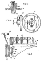
- the spring locating stud 73, a lug 75 for anchoring one end of the pull rope recoil starter spring, a pull rope guide 77, the boss 79 for mounting the pull rope recoil starter, and the previously mentioned exhaust muffler shell 33 may all be cast as an integral part of the engine block rather than fabricating each of these devices as a separate part which must be fastened to the block, requiring additional labor and increased costs.
- valve portion 27 may be of any conventional poppet or lift valve configuration, typically having a tapered seat portion for mating with a similarly tapered seat portion 81 of the engine exhaust port of Figs. 4 and 5.
- the intake port will have a similar tapered seat portion 83 for mating with the intake valve.
- Stem portion 85 is provided with a notch 87 for engagement with the leg 89 of the spring, and leg 97 engages a similar notch in the intake valve stem so that the spring biases both valves toward their closed position.
- Stem end 91 which is the end of the stem opposite the valve 27 fits snugly within the depression 93 of the cam follower or shoe 65 and of course the surface 95 opposite this depression in the shoe is the surface which rides on the surface of radial cam 51. It will be noted that when notch 87 is engaged by the spring leg 89, rotation of the valve about the stem axis will be prevented.
- gears 55 and 57 have a like number of teeth with this number being twice the number of teeth on spur gear 59 so that for each rotation of the spur gear 59, each of the gears 55 and 57 executes one-half revolution.
- the gear 59 is directly driven by the engine crankshaft 37 thereby providing the desired opening and closing of each of the intake and exhaust valves once during two revolutions of the engine.
- a bevel gear 63 engages a substantially smaller bevel gear 61 on the rear side of spur gear 57, as best seen in Figs. 8 and 9, with this substantial disparity in bevel gear sizes, and the two:one speed reduction between gears 59 and 57 providing the desired low speed rotation of the power take-off shaft 71, as for example will be desired to drive the wheels of a power lawnmower.
- Gear 55 may be identical to gear 57 including the bevel gear portion like 61, if the reduction in initial tooling costs as well as the reduction in required spare parts inventory justifies this duplication, or gear 55 may be of a more simplistic design, since it need only drive cam 51. Of course also, somewhat different engine configurations may allow cams 51 and 53 to share a common shaft.
- Figs. 2, 3, 4 and 5 illustrate the integrally cast muffler shell of the present invention.
- an exhaust gas passageway 31 extends from the engine cylinder 23 by way of the exhaust port between valve 27 and seat 81 passing into a substantially enlarged area or cavity as defined by the shell 33 which forms at least a part of the muffler shell.
- a boss 101 also cast as an integral portion of the engine block and having an outwardly facing hole 103 which may be tapped or which may simply be a cast hole for receiving a self- tapping or self-threading screw 105. In either case, the boss provides a support for the muffler baffles 107 and 109.
- each baffle comprises an apertured metal plate for providing a circuitous or tortuous exhaust path from the cavity to the atmosphere.
- this path from exhaust passageway 31 is through the apertures near the bottom of plate 101, then upwardly between the two plates and outwardly through the apertures in the upper portion of plate 107.
- the plates may be substantially identical, each having a generally centrally located depression 111 with the attachment bolt passing aperture 113 within the depression. The plates are positioned with their respective depressions abutting and the remaining plate portions separated by about twice the depth of the depressions and with bolt 105 passing through the respective apertures such as l13 and into boss 101 to securely hold the plates in position near the cavity open end.
- each plate is of a generally rectangular configuration provided with a plurality of small exhaust gas apertures, such as 115 and 117, with those small apertures being concentrated in one half of the rectangular configuration while the other half thereof is substantially aperture free.
- the apertured half of plate 107 is near the top, as illustrated in Fig. 2, while the apertured half of plate 109 is near the bottom of that same Figure.
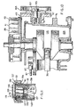
- the combination crankcase breather mechanism and oil fill cap 119 of Fig. 1 functions to restrict an oil filler opening in the engine which communicates by way of an oil fill tube generally at 121 and leading to the engine oil sump 123 (Fig. 10) while providing a flow path for the expulsion of gases from the engine crankcase 125 (Fig. 10) and limiting the egress of oil from the engine through that flow path.
- This breather mechanism cap combination is illustrated in cross-section in F ig.
- the oil fill opening may have a neck 139 with a threaded region 141 which engages a complementary portion of the screw cap 127 about the oil fill opening.
- the upper baffle portion 129 has a downwardly depending generally cylindrical baffle 143 while the lower baffle portion 131 has inner 145 and outer 147 generally cylindrical baffles which are interleaved with the downwardly depending baffle 143.
- the disc 133 of the check valve is captive with a limited amount of free movement between the upper and lower baffle portions. This check valve restricts the entrance of air into the engine crankcase by way of the breather mechanism while allowing the expulsion of gases from the engine crankcase by way of the breather mechanism.
- the expulsion gases pass, as indicated by the arrows, upwardly through the check valve and over an upper rim of the inner lower baffle 145 and then do-nwardly between the baffle and the downwardly depending baffle 143 and beneath a lower rim or edge of baffle 143 to then pass upwardly between the outer lower baffle 147 and the downwardly depending baffle 143, through a plurality of cap apertures, such as 149, 151 and 155 to the atmosphere.
- the inner cylindrical baffle 145 includes a valve seat 153 of an annular configuration while the downwardly depending cylindrical portion 156 of the upper baffle portion restricts the valve disc to movement within the inner cylindrical baffle.
- An oil collecting tray of an annular configuration is formed by the bottom portion 157 which connects the inner and outer baffles from which, as noted earlier, oil drains back to the engine sump by way of drain holes, such as 137. It should also be noted that the location of the cap l19 remote from and substantially above the engine sump oil level, aids materially in the separation of oil from the escaping gases, as those gases pass along the oil fill tube extending from the engine crankcase to the oil filler opening.
Landscapes
- Engineering & Computer Science (AREA)
- Mechanical Engineering (AREA)
- General Engineering & Computer Science (AREA)
- Chemical & Material Sciences (AREA)
- Combustion & Propulsion (AREA)
- Valve-Gear Or Valve Arrangements (AREA)
- Lubrication Details And Ventilation Of Internal Combustion Engines (AREA)
- Exhaust Silencers (AREA)
- Cylinder Crankcases Of Internal Combustion Engines (AREA)
Applications Claiming Priority (2)
| Application Number | Priority Date | Filing Date | Title |
|---|---|---|---|
| US188135 | 1980-09-17 | ||
| US06/188,135 US4380216A (en) | 1980-09-17 | 1980-09-17 | Economical engine construction |
Publications (2)
| Publication Number | Publication Date |
|---|---|
| EP0048183A2 true EP0048183A2 (de) | 1982-03-24 |
| EP0048183A3 EP0048183A3 (de) | 1982-06-23 |
Family
ID=22691904
Family Applications (2)
| Application Number | Title | Priority Date | Filing Date |
|---|---|---|---|
| EP81304289A Withdrawn EP0048183A3 (de) | 1980-09-17 | 1981-09-17 | Brennkraftmaschine |
| EP81304288A Withdrawn EP0048182A1 (de) | 1980-09-17 | 1981-09-17 | Brennkraftmaschine |
Family Applications After (1)
| Application Number | Title | Priority Date | Filing Date |
|---|---|---|---|
| EP81304288A Withdrawn EP0048182A1 (de) | 1980-09-17 | 1981-09-17 | Brennkraftmaschine |
Country Status (7)
| Country | Link |
|---|---|
| US (1) | US4380216A (de) |
| EP (2) | EP0048183A3 (de) |
| JP (1) | JPS5759014A (de) |
| AU (1) | AU7435781A (de) |
| CA (1) | CA1172963A (de) |
| GB (1) | GB2083863A (de) |
| ZA (1) | ZA813972B (de) |
Cited By (1)
| Publication number | Priority date | Publication date | Assignee | Title |
|---|---|---|---|---|
| FR2534626A1 (fr) * | 1982-10-15 | 1984-04-20 | Honda Motor Co Ltd | Moteur a combustion interne tous usages equipe d'un vilebrequin vertical |
Families Citing this family (32)
| Publication number | Priority date | Publication date | Assignee | Title |
|---|---|---|---|---|
| US4602598A (en) * | 1983-01-24 | 1986-07-29 | Locke Moore | Spring and valve skirt |
| JPS61145306A (ja) * | 1984-12-20 | 1986-07-03 | Toyota Motor Corp | V型6気筒dohc内燃機関 |
| US4800856A (en) * | 1985-03-11 | 1989-01-31 | Outboard Marine Corporation | Abrasion resistant roller apparatus for internal combustion engines |
| JPH0219521Y2 (de) * | 1985-04-17 | 1990-05-30 | ||
| JPS6341605A (ja) * | 1986-08-08 | 1988-02-22 | Kawasaki Heavy Ind Ltd | 4サイクルエンジンの動弁機構 |
| US4977863A (en) * | 1989-10-02 | 1990-12-18 | Tecumseh Products Company | Air-cooled internal combustion engine having canted combustion chamber and integral crossover intake manifold |
| EP0425899B1 (de) * | 1989-11-02 | 1994-01-26 | Kubota Corporation | Brennkraftmaschine mit mechanischem Regler und Dekompressionsvorrichtung |
| DE4142811C2 (de) * | 1990-12-26 | 1999-07-22 | Ryobi Ltd | Schmiervorrichtung einer 4-Takt-Brennkraftmaschineneinheit |
| US5241932A (en) * | 1991-12-02 | 1993-09-07 | Ryobi Outdoor Products | Operator carried power tool having a four-cycle engine |
| US5245957A (en) * | 1993-02-04 | 1993-09-21 | Bornstein Motor Company, Inc. | Spring assist system for internal combustion engine valves |
| US5293847A (en) * | 1993-02-16 | 1994-03-15 | Hoffman Ronald J | Powdered metal camshaft assembly |
| US5357917A (en) * | 1993-02-23 | 1994-10-25 | Ryobi Outdoor Products, Inc. | Stamped cam follower and method of making a stamped cam follower |
| US5347967A (en) * | 1993-06-25 | 1994-09-20 | Mcculloch Corporation | Four-stroke internal combustion engine |
| GB2341220A (en) | 1998-09-04 | 2000-03-08 | Cummins Engine Co Ltd | Camshaft alignment and arrangement relative to crankshaft |
| US6349688B1 (en) | 2000-02-18 | 2002-02-26 | Briggs & Stratton Corporation | Direct lever overhead valve system |
| EP2261538B1 (de) * | 2001-07-10 | 2012-03-07 | Nidec Sankyo Corporation | Ventilantrieb |
| US6874458B2 (en) * | 2001-12-28 | 2005-04-05 | Kohler Co. | Balance system for single cylinder engine |
| US6532925B1 (en) | 2002-03-11 | 2003-03-18 | Tecumseh Products Company | Stamped valve spring and retainer |
| US6941914B2 (en) * | 2002-04-15 | 2005-09-13 | Tecumseh Products Company | Internal combustion engine |
| US6739304B2 (en) | 2002-06-28 | 2004-05-25 | Kohler Co. | Cross-flow cylinder head |
| US6684846B1 (en) | 2002-07-18 | 2004-02-03 | Kohler Co. | Crankshaft oil circuit |
| US6732701B2 (en) | 2002-07-01 | 2004-05-11 | Kohler Co. | Oil circuit for twin cam internal combustion engine |
| US6837206B2 (en) * | 2002-07-11 | 2005-01-04 | Kohler Co. | Crankcase cover with oil passages |
| US6978751B2 (en) | 2002-07-18 | 2005-12-27 | Kohler Co. | Cam follower arm for an internal combustion engine |
| US6752846B2 (en) * | 2002-07-18 | 2004-06-22 | Kohler Co. | Panel type air filter element with integral baffle |
| US6837207B2 (en) | 2002-07-18 | 2005-01-04 | Kohler Co. | Inverted crankcase with attachments for an internal combustion engine |
| US6742488B2 (en) | 2002-07-18 | 2004-06-01 | Kohler Co. | Component for governing air flow in and around cylinder head port |
| FR2883600B1 (fr) * | 2005-03-23 | 2010-12-17 | Simcoo | Decompresseur a masselotte centrifuge |
| CA3027536C (en) | 2010-09-23 | 2022-04-12 | Polaris Industries Inc. | Engine |
| US20180264566A1 (en) * | 2017-03-20 | 2018-09-20 | Milwaukee Electric Tool Corporation | Reciprocating saw |
| DE102017206151B3 (de) | 2017-04-11 | 2018-10-11 | Ford Global Technologies, Llc | Brennkraftmaschine umfassend Ventiltriebe mit Ventilfedern und Verfahren zum Montieren einer derartigen Ventilfeder |
| WO2019187094A1 (ja) * | 2018-03-30 | 2019-10-03 | 本田技研工業株式会社 | エンジン |
Family Cites Families (26)
| Publication number | Priority date | Publication date | Assignee | Title |
|---|---|---|---|---|
| GB144494A (en) * | 1919-07-12 | 1920-06-17 | William John George | Improvements in the exhaust pipes of internal combustion engines |
| GB238672A (en) | 1924-07-15 | 1925-08-27 | British Lighting And Ignition | Improvements in or relating to deviating cams for interrupting electric circuits |
| US1974802A (en) * | 1930-09-18 | 1934-09-25 | Wright Aeronautical Corp | Valve spring mechanism |
| CH182801A (fr) * | 1935-04-06 | 1936-02-29 | Douglas Marchant William | Dispositif de rappel de soupape, notamment pour moteur à combustion interne. |
| US2338929A (en) * | 1940-09-24 | 1944-01-11 | Goiot Jean Roger | Starting device for internal combustion engines |
| CH241998A (de) * | 1943-12-28 | 1946-04-15 | Ringhoffer Tatra Werke Ag | Einrichtung zum Antrieb von im Kurbelgehäuse angeordneten Nockenwellen bei luftgekühlten Motoren mit einander gegeüberliegenden Zylindern. |
| GB613386A (en) * | 1946-06-20 | 1948-11-25 | Enfield Cycle Co Ltd | An improved valve system or "breather" for use in connection with the crank cases of internal combustion engines |
| US2539378A (en) * | 1948-02-07 | 1951-01-23 | Fram Corp | Crankcase breather opening filter |
| FR1020632A (fr) * | 1949-12-19 | 1953-02-09 | Poussoir de soupape, en particulier pour moteurs à combustion | |
| US2824554A (en) * | 1956-01-31 | 1958-02-25 | Achilles C Sampietro | Method and means for rotating valves |
| US2875739A (en) * | 1956-06-18 | 1959-03-03 | Continental Motors Corp | Camshaft drive for internal combustion engines |
| US3008687A (en) * | 1958-05-15 | 1961-11-14 | Thompson Ramo Wooldridge Inc | Valve spring retainer and lock |
| GB962449A (en) | 1960-06-15 | 1964-07-01 | Polymer Corp | Valve actuating mechanisms |
| US3105571A (en) * | 1961-10-25 | 1963-10-01 | Sampoll Gabriel | Uniflow exhaust muffler |
| US3160487A (en) * | 1963-02-25 | 1964-12-08 | Novo Ind Corp | Breather cap |
| US3386301A (en) * | 1964-09-16 | 1968-06-04 | Koyama Mikio | Camshaft driving system for internal combustion engines |
| US3375813A (en) * | 1966-01-10 | 1968-04-02 | Eaton Stamping Co | Side-mounted internal combustion engine starter |
| GB1075905A (en) * | 1966-02-25 | 1967-07-19 | Ford Motor Co | Combined oil filler cap and engine ventilator |
| US3545415A (en) * | 1967-04-08 | 1970-12-08 | Nippon Piston Ring Co Ltd | Valve lifter with thin plastic coating |
| US3381774A (en) * | 1967-07-10 | 1968-05-07 | Mercury Metal Products Inc | Muffler with interconnected end bells and telescoped inner pipe |
| US3556062A (en) * | 1968-11-14 | 1971-01-19 | Tecumseh Products Co | Valve spring mechanism for internal combustion engines |
| FR2129420A5 (de) * | 1971-03-08 | 1972-10-27 | Cigala & Bertinetti Sas | |
| GB1395744A (en) * | 1972-05-22 | 1975-05-29 | Automotive Proeucts Ltd | Oil filler cap |
| JPS528253A (en) * | 1975-07-09 | 1977-01-21 | Teijin Ltd | Transparent gear |
| US4090583A (en) * | 1976-02-02 | 1978-05-23 | Leonard James L | Streamlined monolithic internal combustion engine muffler |
| DE2730218A1 (de) * | 1977-07-05 | 1979-01-25 | Solo Kleinmotoren Gmbh | Rasenmaeher mit verbrennungsmotor |
-
1980
- 1980-09-17 US US06/188,135 patent/US4380216A/en not_active Expired - Lifetime
-
1981
- 1981-05-22 CA CA000378146A patent/CA1172963A/en not_active Expired
- 1981-06-12 ZA ZA813972A patent/ZA813972B/xx unknown
- 1981-07-27 JP JP56117584A patent/JPS5759014A/ja active Pending
- 1981-08-20 AU AU74357/81A patent/AU7435781A/en not_active Abandoned
- 1981-09-04 GB GB8126803A patent/GB2083863A/en not_active Withdrawn
- 1981-09-17 EP EP81304289A patent/EP0048183A3/de not_active Withdrawn
- 1981-09-17 EP EP81304288A patent/EP0048182A1/de not_active Withdrawn
Cited By (1)
| Publication number | Priority date | Publication date | Assignee | Title |
|---|---|---|---|---|
| FR2534626A1 (fr) * | 1982-10-15 | 1984-04-20 | Honda Motor Co Ltd | Moteur a combustion interne tous usages equipe d'un vilebrequin vertical |
Also Published As
| Publication number | Publication date |
|---|---|
| GB2083863A (en) | 1982-03-31 |
| EP0048182A1 (de) | 1982-03-24 |
| AU7435781A (en) | 1982-04-08 |
| CA1172963A (en) | 1984-08-21 |
| ZA813972B (en) | 1982-08-25 |
| JPS5759014A (en) | 1982-04-09 |
| US4380216A (en) | 1983-04-19 |
| EP0048183A3 (de) | 1982-06-23 |
Similar Documents
| Publication | Publication Date | Title |
|---|---|---|
| US4380216A (en) | Economical engine construction | |
| US4579092A (en) | Crankcase breather mechanism | |
| US4507917A (en) | Economical engine construction having integrally cast muffler | |
| CA2360001C (en) | Mid cam engine | |
| EP0279445B1 (de) | Brennkraftmaschine mit vertikaler Kurbelwelle für Rasenmäher | |
| US6941914B2 (en) | Internal combustion engine | |
| US20110073064A1 (en) | Integrally cast block and gaseous fuel injected generator engine | |
| US6904883B2 (en) | Modular internal combustion engines | |
| US20140076268A1 (en) | Engine | |
| US6637399B2 (en) | Lubrication structure in OHC engine | |
| CA1192137A (en) | Economical engine construction | |
| CA1181348A (en) | Economical engine construction | |
| EP3779164B1 (de) | Motor | |
| AU2003200621B2 (en) | Mid cam engine | |
| US2693791A (en) | Breather for air-cooled internalcombustion engines | |
| EP3779163B1 (de) | Motor | |
| JPS6224739Y2 (de) | ||
| JPS6339367Y2 (de) | ||
| JPS6157507B2 (de) | ||
| EP3779165B1 (de) | Motor | |
| US20210010444A1 (en) | Engine | |
| JPS5943441Y2 (ja) | オ−バヘツドカムエンジン | |
| JPH0557430B2 (de) | ||
| CA2425354A1 (en) | Internal combustion engine | |
| JPS63125125U (de) |
Legal Events
| Date | Code | Title | Description |
|---|---|---|---|
| PUAI | Public reference made under article 153(3) epc to a published international application that has entered the european phase |
Free format text: ORIGINAL CODE: 0009012 |
|
| AK | Designated contracting states |
Designated state(s): DE FR IT |
|
| PUAL | Search report despatched |
Free format text: ORIGINAL CODE: 0009013 |
|
| AK | Designated contracting states |
Designated state(s): DE FR IT |
|
| 17P | Request for examination filed |
Effective date: 19820624 |
|
| STAA | Information on the status of an ep patent application or granted ep patent |
Free format text: STATUS: THE APPLICATION HAS BEEN WITHDRAWN |
|
| 18W | Application withdrawn |
Withdrawal date: 19830822 |
|
| RIN1 | Information on inventor provided before grant (corrected) |
Inventor name: KANDLER, WILLIAM C. |