EP0048334B1 - Appareil pour le triage de feuilles de verre non triées d'une installation de coupe de verre - Google Patents
Appareil pour le triage de feuilles de verre non triées d'une installation de coupe de verre Download PDFInfo
- Publication number
- EP0048334B1 EP0048334B1 EP19810106154 EP81106154A EP0048334B1 EP 0048334 B1 EP0048334 B1 EP 0048334B1 EP 19810106154 EP19810106154 EP 19810106154 EP 81106154 A EP81106154 A EP 81106154A EP 0048334 B1 EP0048334 B1 EP 0048334B1
- Authority
- EP
- European Patent Office
- Prior art keywords
- glass
- carriage
- compartmented
- compartment
- displaceable
- Prior art date
- Legal status (The legal status is an assumption and is not a legal conclusion. Google has not performed a legal analysis and makes no representation as to the accuracy of the status listed.)
- Expired
Links
- 239000011521 glass Substances 0.000 title claims description 70
- 238000009434 installation Methods 0.000 title claims description 5
- 238000006073 displacement reaction Methods 0.000 description 4
- 239000000872 buffer Substances 0.000 description 3
- 238000000034 method Methods 0.000 description 2
- 238000009825 accumulation Methods 0.000 description 1
- 210000001520 comb Anatomy 0.000 description 1
- 238000005265 energy consumption Methods 0.000 description 1
- 230000001788 irregular Effects 0.000 description 1
- 230000003068 static effect Effects 0.000 description 1
- 238000011144 upstream manufacturing Methods 0.000 description 1
- 239000002699 waste material Substances 0.000 description 1
Images


Classifications
-
- B—PERFORMING OPERATIONS; TRANSPORTING
- B07—SEPARATING SOLIDS FROM SOLIDS; SORTING
- B07C—POSTAL SORTING; SORTING INDIVIDUAL ARTICLES, OR BULK MATERIAL FIT TO BE SORTED PIECE-MEAL, e.g. BY PICKING
- B07C5/00—Sorting according to a characteristic or feature of the articles or material being sorted, e.g. by control effected by devices which detect or measure such characteristic or feature; Sorting by manually actuated devices, e.g. switches
- B07C5/04—Sorting according to size
-
- B—PERFORMING OPERATIONS; TRANSPORTING
- B65—CONVEYING; PACKING; STORING; HANDLING THIN OR FILAMENTARY MATERIAL
- B65G—TRANSPORT OR STORAGE DEVICES, e.g. CONVEYORS FOR LOADING OR TIPPING, SHOP CONVEYOR SYSTEMS OR PNEUMATIC TUBE CONVEYORS
- B65G1/00—Storing articles, individually or in orderly arrangement, in warehouses or magazines
- B65G1/02—Storage devices
- B65G1/04—Storage devices mechanical
-
- B—PERFORMING OPERATIONS; TRANSPORTING
- B65—CONVEYING; PACKING; STORING; HANDLING THIN OR FILAMENTARY MATERIAL
- B65G—TRANSPORT OR STORAGE DEVICES, e.g. CONVEYORS FOR LOADING OR TIPPING, SHOP CONVEYOR SYSTEMS OR PNEUMATIC TUBE CONVEYORS
- B65G49/00—Conveying systems characterised by their application for specified purposes not otherwise provided for
- B65G49/05—Conveying systems characterised by their application for specified purposes not otherwise provided for for fragile or damageable materials or articles
- B65G49/06—Conveying systems characterised by their application for specified purposes not otherwise provided for for fragile or damageable materials or articles for fragile sheets, e.g. glass
- B65G49/062—Easels, stands or shelves, e.g. castor-shelves, supporting means on vehicles
-
- B—PERFORMING OPERATIONS; TRANSPORTING
- B65—CONVEYING; PACKING; STORING; HANDLING THIN OR FILAMENTARY MATERIAL
- B65G—TRANSPORT OR STORAGE DEVICES, e.g. CONVEYORS FOR LOADING OR TIPPING, SHOP CONVEYOR SYSTEMS OR PNEUMATIC TUBE CONVEYORS
- B65G49/00—Conveying systems characterised by their application for specified purposes not otherwise provided for
- B65G49/05—Conveying systems characterised by their application for specified purposes not otherwise provided for for fragile or damageable materials or articles
- B65G49/06—Conveying systems characterised by their application for specified purposes not otherwise provided for for fragile or damageable materials or articles for fragile sheets, e.g. glass
- B65G49/067—Sheet handling, means, e.g. manipulators, devices for turning or tilting sheet glass
-
- B—PERFORMING OPERATIONS; TRANSPORTING
- B65—CONVEYING; PACKING; STORING; HANDLING THIN OR FILAMENTARY MATERIAL
- B65G—TRANSPORT OR STORAGE DEVICES, e.g. CONVEYORS FOR LOADING OR TIPPING, SHOP CONVEYOR SYSTEMS OR PNEUMATIC TUBE CONVEYORS
- B65G49/00—Conveying systems characterised by their application for specified purposes not otherwise provided for
- B65G49/05—Conveying systems characterised by their application for specified purposes not otherwise provided for for fragile or damageable materials or articles
- B65G49/06—Conveying systems characterised by their application for specified purposes not otherwise provided for for fragile or damageable materials or articles for fragile sheets, e.g. glass
- B65G49/068—Stacking or destacking devices; Means for preventing damage to stacked sheets, e.g. spaces
Definitions
- the invention relates to a device according to the preamble of claim 1.
- a device of the type mentioned is known and is available from Alcomag B.V. manufactured and sold in The Hague under the name “Selectronic”.
- the transfer carriage is connected directly to the glass cutting system and is used to hold a single glass pane.
- the disadvantage here is that the sliding carriage must travel along the fan rack for a single glass pane in order to place the glass pane in a compartment of the fan rack. Due to these very long distances, the device is very slow, requires a lot of energy and is subject to high wear and tear, but still does not do justice to the performance of a modern glass cutting system. For this reason, two such systems are usually arranged on both sides of the delivery station of a glass cutting system. This further increases the complexity of such a system.
- the object of the invention is to design a device of the type mentioned at the outset in such a way that it does not have the disadvantages mentioned, but rather achieves high performance with a simple structure and low energy costs.
- the compartment trolley makes it possible to continuously record unsorted glass panes of a glass cutting system, such a compartment trolley being able to easily accommodate the capacity of a glass cutting system.
- This compartment trolley is then placed on the sliding carriage and moved with it, so that the sliding carriage does not have to move from the receiving position for each individual glass pane, but can process a package of glass panes simultaneously. On the one hand, this increases the performance of the sorting device and, on the other hand, there is less energy consumption and a longer service life.
- compartment trolleys can also be provided, which are continuously filled with unsorted glass panes and which can fulfill a buffer function if the accumulation of unsorted glass panes on a glass cutting system is irregular because, for example, batches with small glass panes alternate with those with large glass panes.
- the transfer carriage can be equipped with a transfer bridge which enables the compartment trolley to be given a movement superimposed on the movement of the transfer carriage and the movement of the transfer bridge. This allows the distance of the transfer carriage to be further reduced, since small differences in the transfer path can be compensated for by the transfer bridge. This results in a further increase in the performance of the sorting device while protecting the components at the same time.
- the transfer device can consist, for example, of the compartment trolley having floor rollers which can be driven individually in each compartment and which can be switched on individually from compartment to compartment.
- a simplification of the transfer device results in the embodiment according to claim 3, since only one transfer device is necessary for all compartments of the compartment rack.
- An embodiment of the sorting device according to claim 4 is particularly advantageous since the transfer device has a lower mass than the compartment trolley, so that the transfer device can be operated faster and with less energy expenditure. As a result, a further increase in performance is achieved while reducing the energy requirement.
- a particularly simple design of the transfer device is defined in claim 5, which can be further improved by the configuration according to claim 6.
- a particularly simple control of the sorting device results in an embodiment according to claim 7.
- the pulse counters can then be used directly for evaluating the distance traveled, which results in great variability and there is largely no need for limit switches.
- the sorting device can be controlled, for example, by providing the individual glass panes to be sorted with code markings which are read and processed by the sorting device.
- an embodiment according to claim 9 is particularly advantageous, since here the upstream glass cutting system can be used directly to control the sorting device.
- the cutting plan specifies exactly which glass panes arrive at the delivery station, so that this information can be used to control the sorting device.
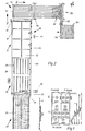
- Figure 1 shows a glass sheet T, which according to egg a cutting plan is to be divided into individual glass panes S.
- This cutting plan is created by an electronic computing control device of a cutting machine. The data of several orders and the mass of the glass sheets to be processed are entered into this electronic computer control unit. The electronic computer control unit then uses this data to determine the optimal cutting plan with the least waste. However, the individual glass panes S to be cut from different orders are mixed.
- the cutting plan shown contains, for example, glass plates of orders 3, 6, 7, 9, 12 and 15.
- the cutting plan is composed of X cuts that go from edge to edge of the glass sheet and Y cuts that go from X cut to X. - go through the cut. If necessary, the cutting plan can have additional Z cuts that run from Y cut to Y cut.
- the X o section forms the reference section from which the individual masses are removed.
- the right edge of the glass panel also forms the reference base for the Y cuts.
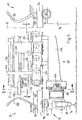
- FIG. 2 shows a system for cutting glass sheets T, which has a tilting table 20 which can be tilted into an approximately vertical position for receiving a glass sheet T.
- the glass panel T is put on and the tilting table swings back into its horizontal position.
- the tilting table contains a roller base 22 on which the glass sheet is conveyed to the cutting machine 24.
- This is preferably constructed in accordance with DE-C-2160545, an air cushion table 26 with a conveyor belt 28 being used to transport the glass sheet. This is aligned with stops 30.
- a cutting carriage 32 which can be moved along the air cushion table 26 and has insertable cutting tools 34, is used to cut the glass sheet.
- An electronic computer control device 36 is used to program the cutting machine 24.
- An intermediate conveyor 38 connects to the cutting machine 24, which can optionally be designed as a break table and for this purpose has break bars 40 and 42 running in the X direction and in the Y direction Control panel 44 can be operated individually.
- the intermediate conveyor also contains an alignment device 46 for aligning the cut glass sheets in the Y direction.
- a first crushing machine 48 is connected to the intermediate conveyor, which is designed as a static crushing machine and is used to successively break open the X-cuts that go through the entire glass sheet.
- the individual glass sheet sections arrive at a deflecting table 50 with a roller bend 52 effective in the Y direction and an apron base 54 effective in the X direction, which are used alternately.
- a second crushing machine 56 is connected to the deflecting table 50 in the X direction, which is designed as a dynamic crushing machine and is used to successively break open the Y cuts that are continuous from X cut to X cut.
- the individual glass panes S now arrive at the delivery station 58, at which they are placed vertically by means of an installation device 60. Via a conveyor device 62, the glass panes arrive standing at a compartment trolley 64, in which they are placed one after the other in compartments 66.
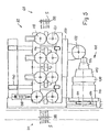
- the sorting device contains a compartment set 68, which is also formed, for example, from compartment trolleys 70.
- the compartment frame 68 consists of five such compartment trolleys 70.
- a sliding carriage 72 can be moved along rails 74 between buffers 76 and 78 along this compartment frame 68.
- the sliding carriage 72 contains a drive, not shown, which preferably contains a disk motor and an encoder.
- a guide rail 80 is arranged, on which a transfer device 82 can be moved along the sliding carriage 72.
- the sliding carriage 72 carries a compartment trolley 64 filled with glass panes.
- the transfer device 82 interacts with each compartment 66 of the compartment trolley 64, as will be explained in more detail below.
- the transfer device 82 serves to remove a glass pane from a compartment 66 of the compartment trolley 64 and to deposit the glass pane in a compartment 84 of the compartment rack 68.
- the fan carriage 64 and the fan frame 68 consist of a frame 86 on which brackets 88 formed from tubes are arranged, which form the compartments 66 and 84 between them.
- the glass panes S are supported on rollers 90 on the underside of the compartments.
- the frames 86 of the trolley 67 or the fan frame 68 rest on rollers 92 of the transfer carriage 72 or on rollers 94 of a frame 96 which carries the fan frame 68.
- the sliding carriage 72 contains rollers 98 which roll on the rails 74.
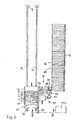
- the transfer device 82 which is shown in particular in FIGS. 4 to 6, runs on guide rails 80 of the sliding carriage 72.
- a frame 100 has rollers which interact with the guide rails 80, and a drive device 102 which engages with a rack 106 by means of a spur gear 104 the guide rail 80 combs.
- the drive device includes a disc motor 108 which is connected to the spur gear 104 via a gear 110.
- the drive device further contains a brake 112 and a pulse generator 114.
- Lower frame support rollers 116 which are freely rotatable on the frame 100 and lateral guide rollers 118 and drive rollers 120 are provided on the frame 100 for receiving and transferring the glass sheets S.
- the transfer device 82 further includes pliers 126 which are attached to a holder 128 is arranged, on which a plunger 130 is also attached.
- a piston / cylinder unit 132 serves to move the holder 128 with the pliers 126 and the plunger 130 into the travel path of a glass pane S.
- Another piston / cylinder unit 134 serves to open and close the pliers 126.
- the holder 128 is moved back and forth in the direction of the compartments 66 and 84 by means of a further piston / cylinder unit 136.
- the holder 128 with the piston / cylinder unit 132 is brought into the displacement path of the glass pane S, and by means of of the piston / cylinder unit 136 moved into the compartment 66 of the compartment trolley 64.
- the pliers 126 are closed by means of the piston / cylinder unit 134 and the latter holds the glass pane in place.
- the glass pane S is pulled out of the compartment of the compartment trolley until it reaches the engagement area of the guide rollers 118 or drive rollers 120.
- the pliers 126 are opened, extended and withdrawn.
- the foremost guide roller 118 is pressed against the drive rollers 120 by means of a piston / cylinder unit 138, so that the glass pane S is carried along by them.
- the plunger 130 is retracted and moved by means of the piston / cylinder unit 136, so that the glass pane is completely pushed into a corresponding compartment 84 of the compartment frame 68.
- the frame 100 of the transfer device 82 has vertically extending supports 140 which carry support rollers 142 in order to hold and guide the glass pane S.
- a control device 143 which is not shown in detail, is used to control the sorting device.
- the sorting process can be controlled, for example, by providing the individual glass panes to be sorted with code markings which are read and processed by the transfer device.
- the control device is coupled to the computer control unit 36 of the glass cutting system in order to control the sorting device in accordance with the cutting plan of the glass cutting system.
- the cutting plan specifies exactly which glass sheet arrives at the delivery station 58 and is thus delivered to the compartment trolley. This information can be processed in the control device 143 in a known manner and can control the transfer carriage 72 and the transfer device 82.
- the further control of the transfer carriage and the transfer device 82 can be carried out in the usual manner e.g. done by limit switches in the form of mechanical, electrical, electro-optical switches, etc.
- a particularly simple control of the sorting device is obtained if at least one, preferably all of the following structural units: transfer carriages 72, drives of the transfer device 82 have pulse generators 114 which are coupled to the control device. The pulse counters can then be used directly to evaluate the distance traveled, which results in great variability and there is largely no need for limit switches.
- FIG. 7 shows a further exemplary embodiment of a sorting device in which the compartment carriage 64 is arranged on a displacement bridge 144 which can be moved on rails 146 of the displacement carriage 148, the length of the displacement path corresponding at least to the length of the compartment carriage 64.
- the sliding carriage 148 is in turn movable on rails 150 between buffers 152 and 154 along the compartment frame 68.
- the transfer device 156 is fixedly attached to the sliding carriage 148 and contains an ejection device 158, with a plunger 160, which transfers individual glass panes S from the compartment carriage 64 into the compartment rack 68.
- the transfer device 156 is attached to the side of the sliding carriage 148 which faces away from the compartment frame 68.
Landscapes
- Engineering & Computer Science (AREA)
- Mechanical Engineering (AREA)
- Re-Forming, After-Treatment, Cutting And Transporting Of Glass Products (AREA)
Claims (9)
Applications Claiming Priority (2)
| Application Number | Priority Date | Filing Date | Title |
|---|---|---|---|
| CH713580 | 1980-09-24 | ||
| CH7135/80 | 1980-09-24 |
Publications (2)
| Publication Number | Publication Date |
|---|---|
| EP0048334A1 EP0048334A1 (fr) | 1982-03-31 |
| EP0048334B1 true EP0048334B1 (fr) | 1984-03-07 |
Family
ID=4320507
Family Applications (1)
| Application Number | Title | Priority Date | Filing Date |
|---|---|---|---|
| EP19810106154 Expired EP0048334B1 (fr) | 1980-09-24 | 1981-08-06 | Appareil pour le triage de feuilles de verre non triées d'une installation de coupe de verre |
Country Status (2)
| Country | Link |
|---|---|
| EP (1) | EP0048334B1 (fr) |
| DE (1) | DE3162520D1 (fr) |
Cited By (8)
| Publication number | Priority date | Publication date | Assignee | Title |
|---|---|---|---|---|
| FR2615167A1 (fr) * | 1987-05-11 | 1988-11-18 | Peugeot | Installation pour le rangement dans des conteneurs de pieces de vehicules automobiles |
| EP0341673A3 (fr) * | 1988-05-11 | 1990-09-12 | Tamglass Oy | Système de stockage intermédiaire pour paires de plaques de verre dans une chaíne de production de pare-brises |
| WO1991003434A1 (fr) * | 1989-08-31 | 1991-03-21 | Abracad Systems Limited | Appareil de manipulation de matiere en nappe |
| EP0477163A1 (fr) * | 1990-09-18 | 1992-03-25 | Peter Lisec | Dispositif pour trier des découpes de plaques de verre |
| EP0620171A1 (fr) * | 1993-04-14 | 1994-10-19 | Bystronic Maschinen AG | Installation pour ranger des matériaux en feuilles |
| US6077018A (en) * | 1996-07-03 | 2000-06-20 | Lisec; Peter | Device for sorting of glass blanks |
| DE20216438U1 (de) * | 2002-10-24 | 2004-03-04 | Lisec, Peter | Glasschneideanlage mit Zwischenspeicher |
| CN105800925A (zh) * | 2016-03-11 | 2016-07-27 | 东莞市银锐精密机械有限公司 | 一种全自动玻璃分切流水线 |
Families Citing this family (15)
| Publication number | Priority date | Publication date | Assignee | Title |
|---|---|---|---|---|
| AT402194B (de) * | 1994-03-24 | 1997-02-25 | Lisec Peter | Verfahren und anlage zum sortieren von zuschnitten |
| AT401507B (de) * | 1994-03-28 | 1996-09-25 | Lisec Peter | Vorrichtung zum entnehmen von tafelförmigen gegenständen |
| DE10139715B4 (de) | 2001-08-13 | 2005-02-03 | Hegla Fahrzeug- Und Maschinenbau Gmbh & Co Kg | Verfahren und Vorrichtung zum Bearbeiten von Glastafeln |
| DE10164071A1 (de) | 2001-12-24 | 2003-07-03 | Hegla Fahrzeug Und Maschb Gmbh | Verfahren und Vorrichtung zum Sortieren von Glastafeln |
| CA2460859A1 (fr) | 2003-03-13 | 2004-09-13 | Bromer Inc. | Systeme de stockage des chutes de verre |
| CA2421121A1 (fr) | 2003-03-13 | 2004-09-13 | Roger Mercure | Dispositif et methode pour la valorisation et l'optimisation de panneaux a decouper |
| DE502005000996D1 (de) * | 2004-04-23 | 2007-08-23 | Helga Fahrzeug Und Maschb Gmbh | Beladevorrichtung zum sortierenden Beladen einer Speichereinrichtung mit plattenförmigem Material |
| ATE537126T1 (de) | 2006-08-17 | 2011-12-15 | Albat & Wirsam Software Ag | Verfahren und vorrichtung zum zuschneiden von rohglasplatten |
| DE102011106780B4 (de) | 2011-07-06 | 2017-03-30 | Klaus Knaust | Scheibensortierer |
| DE102017005809B4 (de) * | 2017-06-20 | 2019-07-18 | Grenzebach Maschinenbau Gmbh | Vorrichtung und Verfahren zum sicheren und schnellen Transfer neuer Glasplatten von der Fertigungslinie zu einem Transportfahrzeug |
| DE102018218141B4 (de) | 2018-05-04 | 2022-03-24 | Hegla Gmbh & Co. Kg | Sortierverfahren und -vorrichtung zum Sortieren von plattenförmigen Gegenständen, vorzugsweise Glastafelzuschnitten, Verfahren und Vorrichtung zum Herstellen von Glastafelzuschnitten mit einer derartigen Sortiervorrichtung |
| DE102019115571B4 (de) * | 2019-06-07 | 2021-11-11 | Bystronic Laser Ag | Schnelles Abtransportieren von geschnittenen Teilen aus einer Verarbeitungsanlage |
| US11673749B2 (en) * | 2019-09-06 | 2023-06-13 | Billco Manufacturing Incorporated | Glass cutting line with automatic remnant storage and retrieval including cutting table with integrated squaring stop and Y-break breaking bar facilitating sub-plate cutting |
| CN112224609A (zh) * | 2020-08-29 | 2021-01-15 | 江苏晶品新能源科技有限公司 | 一种智能化单晶硅片分拣装置 |
| ES2991313T3 (es) | 2021-05-04 | 2024-12-03 | Hubert Haselsteiner | Método y sistema para cargar una unidad de tratamiento térmico |
Family Cites Families (4)
| Publication number | Priority date | Publication date | Assignee | Title |
|---|---|---|---|---|
| US2902168A (en) * | 1958-09-15 | 1959-09-01 | Jr Byron W Allen | Plate glass storage rack |
| US3698577A (en) * | 1970-08-21 | 1972-10-17 | Dean Research Corp | Transporting system |
| DE2539352C3 (de) * | 1975-09-04 | 1979-09-20 | Bfg Glassgroup, Paris | Vorrichtung zum Einführen von halbfertigen Isolierglasscheiben in einen vertikale schmale Fächer aufweisenden Wagen |
| NZ189642A (en) * | 1978-02-20 | 1983-02-15 | Pilkington Brothers Ltd | Apparatus for transferring sheet material |
-
1981
- 1981-08-06 DE DE8181106154T patent/DE3162520D1/de not_active Expired
- 1981-08-06 EP EP19810106154 patent/EP0048334B1/fr not_active Expired
Cited By (12)
| Publication number | Priority date | Publication date | Assignee | Title |
|---|---|---|---|---|
| FR2615167A1 (fr) * | 1987-05-11 | 1988-11-18 | Peugeot | Installation pour le rangement dans des conteneurs de pieces de vehicules automobiles |
| EP0341673A3 (fr) * | 1988-05-11 | 1990-09-12 | Tamglass Oy | Système de stockage intermédiaire pour paires de plaques de verre dans une chaíne de production de pare-brises |
| WO1991003434A1 (fr) * | 1989-08-31 | 1991-03-21 | Abracad Systems Limited | Appareil de manipulation de matiere en nappe |
| EP0477163A1 (fr) * | 1990-09-18 | 1992-03-25 | Peter Lisec | Dispositif pour trier des découpes de plaques de verre |
| AT394987B (de) * | 1990-09-18 | 1992-08-10 | Lisec Peter | Vorrichtung zum sortieren von glastafelzuschnitten |
| US5209627A (en) * | 1990-09-18 | 1993-05-11 | Peter Lisec | Apparatus for sorting cut glass sheets |
| EP0620171A1 (fr) * | 1993-04-14 | 1994-10-19 | Bystronic Maschinen AG | Installation pour ranger des matériaux en feuilles |
| US5511671A (en) * | 1993-04-14 | 1996-04-30 | Bystronic Maschinen Ag | Installation for the sorting of plate material |
| US6077018A (en) * | 1996-07-03 | 2000-06-20 | Lisec; Peter | Device for sorting of glass blanks |
| DE20216438U1 (de) * | 2002-10-24 | 2004-03-04 | Lisec, Peter | Glasschneideanlage mit Zwischenspeicher |
| CN105800925A (zh) * | 2016-03-11 | 2016-07-27 | 东莞市银锐精密机械有限公司 | 一种全自动玻璃分切流水线 |
| CN105800925B (zh) * | 2016-03-11 | 2019-03-01 | 东莞市银锐精密机械有限公司 | 一种全自动玻璃分切流水线 |
Also Published As
| Publication number | Publication date |
|---|---|
| DE3162520D1 (en) | 1984-04-12 |
| EP0048334A1 (fr) | 1982-03-31 |
Similar Documents
| Publication | Publication Date | Title |
|---|---|---|
| EP0048334B1 (fr) | Appareil pour le triage de feuilles de verre non triées d'une installation de coupe de verre | |
| DE2756422C2 (de) | Fertigungsanlage für in mehreren Schritten herzustellende Bauteile | |
| DE2760217C2 (fr) | ||
| DE102006014454B3 (de) | Stanzvorrichtung mit Zuführeinrichtung | |
| DE1149976B (de) | Verfahren und Vorrichtung zum Ausbrechen der Abfaelle oder der Nutzen aus gestanzten Werkstuecken | |
| EP2802727B1 (fr) | Dispositif et procédé d'assemblage de vitrages isolants | |
| DE69602164T2 (de) | Automatische bohr- und fräsmaschine für glassplatten | |
| EP0164063A2 (fr) | Machine-outil pour l'usinage des planches | |
| DE1245547B (de) | Geraet zum Schneiden einer Glasplatte laengs zweier Gruppen paralleler Linien | |
| EP0242762B1 (fr) | Dispositif pour conduire une pile de feuilles à un dispositif de coupe | |
| DE3716666C2 (de) | Plattenaufteilanlage mit einer Längssäge und einer Quersäge | |
| DE3020292A1 (de) | Maschine zum rillen von platten, insbesondere fuer gedruckte schaltungen | |
| EP0771248A1 (fr) | Procede de production par usinage de profiles allonges de longueur definitive | |
| DE3618384A1 (de) | Fertigungs- und verpackungsanlage fuer karten, insbesondere spielkarten | |
| EP0540505B1 (fr) | Installation pour empiler des pièces à usiner partagées en forme de plaques individuelles ou en paquets | |
| DE3737228C2 (fr) | ||
| EP0150809B1 (fr) | Dispositif pour évacuer et empiler des pièces de tôle tombant derrière la ligne de coupe d'une cisaille guillotine | |
| EP0489681B1 (fr) | Procédé et dispositif pour déplacer des pièces en forme de bandes ou de panneaux, empilés et juxtaposés sur une surface de support à faible coefficient de frottement | |
| DE19822282C1 (de) | Vorrichtung zum Glasschneiden | |
| AT398547B (de) | Plattenaufteilanlage | |
| EP1018410A1 (fr) | Procédé et dispositif d'accumulation tampon de piles découpées de produits en feuilles | |
| DE10047385C2 (de) | Verfahren und Vorrichtung zur Bearbeitung von fortlaufend bewegten Werkstücken | |
| AT385449B (de) | Vorrichtung zum aufteilen von plattenfoermigen werkstuecken | |
| DE2153042C3 (de) | Langnahtnäheinrichtung mit Beschickungsvorrichtung | |
| DE4201623C2 (de) | Einrichtung zum Buntaufteilen von plattenförmigen Werkstücken |
Legal Events
| Date | Code | Title | Description |
|---|---|---|---|
| PUAI | Public reference made under article 153(3) epc to a published international application that has entered the european phase |
Free format text: ORIGINAL CODE: 0009012 |
|
| 17P | Request for examination filed |
Effective date: 19811202 |
|
| AK | Designated contracting states |
Designated state(s): BE CH DE FR GB IT NL SE |
|
| ITF | It: translation for a ep patent filed | ||
| GRAA | (expected) grant |
Free format text: ORIGINAL CODE: 0009210 |
|
| AK | Designated contracting states |
Designated state(s): BE CH DE FR GB IT LI NL SE |
|
| REF | Corresponds to: |
Ref document number: 3162520 Country of ref document: DE Date of ref document: 19840412 |
|
| ET | Fr: translation filed | ||
| PG25 | Lapsed in a contracting state [announced via postgrant information from national office to epo] |
Ref country code: SE Effective date: 19840807 |
|
| PG25 | Lapsed in a contracting state [announced via postgrant information from national office to epo] |
Ref country code: LI Effective date: 19840831 Ref country code: CH Effective date: 19840831 |
|
| PLBE | No opposition filed within time limit |
Free format text: ORIGINAL CODE: 0009261 |
|
| STAA | Information on the status of an ep patent application or granted ep patent |
Free format text: STATUS: NO OPPOSITION FILED WITHIN TIME LIMIT |
|
| BERE | Be: lapsed |
Owner name: BYSTRONIC MASCHINEN A.G. Effective date: 19840806 |
|
| 26N | No opposition filed | ||
| PG25 | Lapsed in a contracting state [announced via postgrant information from national office to epo] |
Ref country code: FR Free format text: LAPSE BECAUSE OF NON-PAYMENT OF DUE FEES Effective date: 19850430 |
|
| REG | Reference to a national code |
Ref country code: CH Ref legal event code: PL |
|
| PG25 | Lapsed in a contracting state [announced via postgrant information from national office to epo] |
Ref country code: DE Effective date: 19850501 |
|
| REG | Reference to a national code |
Ref country code: FR Ref legal event code: ST |
|
| PGFP | Annual fee paid to national office [announced via postgrant information from national office to epo] |
Ref country code: NL Payment date: 19850831 Year of fee payment: 5 |
|
| PG25 | Lapsed in a contracting state [announced via postgrant information from national office to epo] |
Ref country code: NL Effective date: 19870301 |
|
| NLV4 | Nl: lapsed or anulled due to non-payment of the annual fee | ||
| GBPC | Gb: european patent ceased through non-payment of renewal fee | ||
| PG25 | Lapsed in a contracting state [announced via postgrant information from national office to epo] |
Ref country code: GB Effective date: 19881118 |
|
| PG25 | Lapsed in a contracting state [announced via postgrant information from national office to epo] |
Ref country code: BE Effective date: 19890831 |
|
| EUG | Se: european patent has lapsed |
Ref document number: 81106154.8 Effective date: 19850612 |