EP0048382A2 - Dispositif de prise de vues radiographiques comportant un porte-film déplaçable d'une position de garage à une position de prise de vue - Google Patents
Dispositif de prise de vues radiographiques comportant un porte-film déplaçable d'une position de garage à une position de prise de vue Download PDFInfo
- Publication number
- EP0048382A2 EP0048382A2 EP81107038A EP81107038A EP0048382A2 EP 0048382 A2 EP0048382 A2 EP 0048382A2 EP 81107038 A EP81107038 A EP 81107038A EP 81107038 A EP81107038 A EP 81107038A EP 0048382 A2 EP0048382 A2 EP 0048382A2
- Authority
- EP
- European Patent Office
- Prior art keywords
- film carrier
- recording device
- ray
- cassette
- ray recording
- Prior art date
- Legal status (The legal status is an assumption and is not a legal conclusion. Google has not performed a legal analysis and makes no representation as to the accuracy of the status listed.)
- Granted
Links
Images

Classifications
-
- A—HUMAN NECESSITIES
- A61—MEDICAL OR VETERINARY SCIENCE; HYGIENE
- A61B—DIAGNOSIS; SURGERY; IDENTIFICATION
- A61B6/00—Apparatus or devices for radiation diagnosis; Apparatus or devices for radiation diagnosis combined with radiation therapy equipment
- A61B6/42—Arrangements for detecting radiation specially adapted for radiation diagnosis
- A61B6/4283—Arrangements for detecting radiation specially adapted for radiation diagnosis characterised by a detector unit being housed in a cassette
-
- G—PHYSICS
- G03—PHOTOGRAPHY; CINEMATOGRAPHY; ANALOGOUS TECHNIQUES USING WAVES OTHER THAN OPTICAL WAVES; ELECTROGRAPHY; HOLOGRAPHY
- G03B—APPARATUS OR ARRANGEMENTS FOR TAKING PHOTOGRAPHS OR FOR PROJECTING OR VIEWING THEM; APPARATUS OR ARRANGEMENTS EMPLOYING ANALOGOUS TECHNIQUES USING WAVES OTHER THAN OPTICAL WAVES; ACCESSORIES THEREFOR
- G03B42/00—Obtaining records using waves other than optical waves; Visualisation of such records by using optical means
- G03B42/02—Obtaining records using waves other than optical waves; Visualisation of such records by using optical means using X-rays
- G03B42/025—Positioning or masking the X-ray film cartridge in the radiographic apparatus
-
- A—HUMAN NECESSITIES
- A61—MEDICAL OR VETERINARY SCIENCE; HYGIENE
- A61B—DIAGNOSIS; SURGERY; IDENTIFICATION
- A61B6/00—Apparatus or devices for radiation diagnosis; Apparatus or devices for radiation diagnosis combined with radiation therapy equipment
- A61B6/54—Control of apparatus or devices for radiation diagnosis
- A61B6/548—Remote control of the apparatus or devices
Definitions
- the invention relates to an X-ray recording device with a film carrier that can be moved from a standby position into at least one recording position and back again with displaceable clamping jaws for holding X-ray film cassettes of different formats.
- an X-ray target device or X-ray cassette changer in which an X-ray film cassette can be moved by motor from a standby position into a receiving position.
- tension dividers are adjusted by the clamping jaws that can be brought into contact with the edges of the cassette.
- Their resistance values are switched on, together with a constant value for the path specification for controlling the entry path of the cassette carriage, from the ready position into the receiving position of a motor-driven follow-up control. These resistance values can also be connected to a further tracking control for presetting the primary beam diaphragm.
- the voltage dividers which convert the tapped cassette dimensions into electrical quantities, must be in electrical connection with the X-ray recording device and, in the case of a corresponding control of the primary radiation aperture, also in an electrical connection with the rest of the X-ray examination apparatus.
- the voltage dividers coupled to the clamping jaws must either be hard-wired to the rest of the X-ray examination device or else be connected to it by means of a plug connection. Both prevent or hinder the removal of the film carrier.
- DE-PS 24 15 410 discloses a cassette sheet which can be inserted under an examination table, in which the clamping jaws adjust a permanent magnet which is displaceably mounted transversely to the direction of insertion via a cable in the cassette sheet. Depending on its position, this permanent magnet activates one of several reed contacts installed in the longitudinal carriage of the examination table when the cassette sheet is inserted. This reed contact then switches a corresponding resistor into a follow-up control for the primary beam aperture and thus adjusts it to the taped dimensions. It is a peculiarity of this construction that the cassette sheet does not need any electrical connections and can therefore be easily removed from the examination table, but can only be used for certain discrete, adapted cassette dimensions.
- the present invention is therefore based on the object of showing a way how the advantages of an automatic beam insertion and an automatic path specification due to the taped cassette dimensions can also be used for X-ray aiming devices, flat diaphragms and such cassette sheets which are useful in such investigations in which they are not are required to be completely removed again from the X-ray system to the full freedom of movement of other components unit does not affect the Röntgenuntersuchungs- '.
- this solution should allow the use of cartridges of any size, while being robust and inexpensive.
- the film carrier and the clamping jaws are therefore coupled to sensors according to the invention, the sensors of the clamping jaws being adjustable relative to the latter in the direction of displacement of the film carrier depending on the span of each pair of clamping jaws, and the sensors are assigned to the sensors who use the guides for the film carrier are connected and connected to a measured value processing arrangement together with an actual value transmitter for the travel of the film carrier.
- the distances of the clamping jaws uppeD E n donors are proportion of the uppelen with the cassette holder encoder - nal the cassette dimensions tapped on the associated jaws. This is a basic requirement for simple processing of measured values.
- the adjustment of the encoders in the direction of displacement of the cassette carriage is a prerequisite for further refinements of the invention.
- the consumers can be light barriers, between which flat, opaque plates can be passed as sensors.
- the film carrier with its clamping jaws can be made without any electrical connections. This has the consequence that the film carrier can be easily pulled out of the X-ray examination device. This can a. should be the case if fluoroscopy is to be carried out and the displaceability of the fluoroscopy device in the longitudinal direction of the table should not be impaired by a film carrier placed at the foot or head end of the examination table.
- the actual value transmitter for the travel of the film carrier can generate a predetermined number of pulses per distance traveled. This construction not only results in linear measurement value processing in connection with the linear adjustment of the Geiger film carrier, but also leads to a relatively simple further measurement value processing with relatively inexpensive digital components.
- the pulses arriving in the interval between the sensors of the film carrier passed by a customer and the corresponding clamping jaw can be separated separately as actual values. value input of the taped cassette size can be counted.
- the pulses counted in this way are a direct measure of the corresponding width or length of the X-ray film cassette. Their acceptance is completely independent of the speed at which the film carrier with the three sensors is guided past the customers.
- the actual value transmitter can be used both for positioning the film carrier and for measuring the width and height of the inserted X-ray film cassette, so that the determination of the dimensions of the X-ray film cassette and the corresponding displacement of the cassette holder from the ready position to the receiving position and back again by one show pulse generator and three measuring marks or sensors can be made. It does not matter whether a servomotor is controlled or if the film carrier is manually adjusted, it is locked in the receiving positions by means of magnetic brakes.
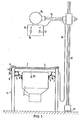
- FIG. 1 shows an examination table 1 with a patient support plate 2 and with one under the patient support plate in a longitudinal direction of the table movable longitudinal carriage 3, retractable film carrier 4, in the exemplary embodiment a cassette plate 4.
- An image intensifier television device 8 mounted in a holder plate 5 and displaceable in guide rails 6, 7 in the longitudinal direction of the table, is mounted under the longitudinal carriage of the examination table.
- the image intensifier television device 8 is connected to the longitudinal carriage 3 via two coupling plates 9, 10.
- a stand column 12 that can be moved on the floor in a rail 11 can be seen, which supports an X-ray tube 14 with an adjustable primary beam diaphragm 15 on a horizontal arm 13 above the examination table.
- the primary beam diaphragm can be adjusted manually with the help of the adjusting knobs 16, 17. These knobs are also adjustable via remote-controlled actuators (not shown).
- the primary radiation diaphragm 15 is connected to the examination table via an electrical cable 18
- FIG. 2 shows a schematic representation of part of the frame 19 of the longitudinal carriage 3 that can be displaced in the longitudinal direction of the examination table 1 below the patient support plate 2.
- the cassette plate 4 is shown in FIG. 2 pulled out of the longitudinal carriage. At its four corners it carries ball bearings 20, 21, 22, 23, with which it can be inserted transversely to the examination table 1 in the side frame parts of the longitudinal carriage 3 made of U-rails 24, 25.
- An endless conveyor belt 26 can be seen along the cassette plate 4.
- the conveyor belt is stretched over two rollers 27, 28, one of which is driven by a motor 29.
- the rollers 27, 28 are at the two ends of the left in FIG. 2, for the sake of clarity greatly shortened U-rail 24 des Longitudinal carriage 3 stored.
- the conveyor belt 26 carries a coupling piece 30 into which a tongue 31 of the cassette plate 4 can be inserted.
- a perforated disc 32 On the axis of the motor 29, a perforated disc 32 is secured against rotation. This perforated disk rotates with its holes between the light sources 34, 35 and photocells 36, 37 of two light barriers 38, 39 fastened on opposite sides of a; U-shaped support body 33. The mutual distance between the two light barriers 38, 39 is an odd multiple of the hole spacing on the perforated disc 32.
- Both the photocells 36, 37 of the two light barriers assigned to the perforated disk 32 and the photocell 56 of the light barrier 54 assigned to the reflection foils 45, 46, 47 are connected to a measured value processing arrangement 57. This in turn is connected to the motor 29 for the displacement of the cassette plate 4 and to the primary beam aperture 15.
- the cassette sheet As long as the cassette sheet is removed from the frame-shaped longitudinal carriage 3, the latter can be shone through without shadows. This means that it can be connected as a frame 19 to the image intensifier television device 8 located underneath. In this case, it also does not hinder the displaceability of the image intensifier television device in the longitudinal direction of the examination table 1.
- the cassette plate 4 If an X-ray image is to be taken with the aid of an X-ray film cassette 44, the cassette plate 4 can be inserted into the U-rails 24, 25 of the longitudinal carriage 3 and in the process its tongue 31 to be coupled to the coupling piece 30 of the conveyor belt 26.
- An X-ray film cassette 44 of a suitable size can now be inserted between the clamping jaws 40, 41, 42, 43.
- the clamping jaws place 40, 41, 42, 43 in known manner to the end edges of the X-ray film cassette and center them to the center of the cassette plate 4. Now, the distance corresponds to the connected to the two adjustable clamping jaws 4 0, 43 Reflective foils 45, 47 for the reflective foil 46 rigidly attached to the cassette sheet 4 of the height or the width of the X-ray film cassette.
- the motor 29 can be switched on for the transport of the cassette plate 4 in a manner not shown here. It moves the conveyor belt 26 with the coupling piece 30 and the cassette plate coupled to the conveyor belt via the inserted tongue 31 into the receiving position.
- the two light barriers 38, 39 assigned to the round perforated disk 32 count the holes in the perforated disk 32 that pass them. Their number is - as has already been described in detail in DE-OS 24 10 146 - a measure of the amount and of the direction of the travel.
- the photocell 56 of this light barrier each generates a pulse which is forwarded to the measured value processing arrangement 57.
- the pulses generated in the time interval between the passage of the reflective film 45, 47, each connected to the clamping jaw 40, 43, and the reflective film 46, which is firmly connected to the cassette sheet 4, are counted in a special counter of the measured value processing arrangement 57. They are a measure of the length or the width of the X-ray film cassette 44 clamped on the cassette plate 4 and can be used by the measured value processing arrangement to control the entry of the cassette plate into the receiving position.
- the 1: 2 reduced pulses counted for the cassette dimensions can be counted or counted directly to the given pulses, which correspond to the normal travel path of the cassette plate for undivided recordings, in order to Actuator in the to switch off the two exposure positions calculated in this way in the case of two-part exposure.
- a follow-up control for the setting of the primary beam diaphragm 15 can be fed.
- the longitudinal carriage 3 or a part thereof can be adjusted with the U-rails due to the taped tape dimensions for film division in the table longitudinal direction.
Landscapes
- Health & Medical Sciences (AREA)
- Life Sciences & Earth Sciences (AREA)
- Medical Informatics (AREA)
- Engineering & Computer Science (AREA)
- Physics & Mathematics (AREA)
- Radiology & Medical Imaging (AREA)
- Surgery (AREA)
- Nuclear Medicine, Radiotherapy & Molecular Imaging (AREA)
- Optics & Photonics (AREA)
- Pathology (AREA)
- Biophysics (AREA)
- Biomedical Technology (AREA)
- Heart & Thoracic Surgery (AREA)
- Molecular Biology (AREA)
- High Energy & Nuclear Physics (AREA)
- Animal Behavior & Ethology (AREA)
- General Health & Medical Sciences (AREA)
- Public Health (AREA)
- Veterinary Medicine (AREA)
- General Physics & Mathematics (AREA)
- Apparatus For Radiation Diagnosis (AREA)
- Radiography Using Non-Light Waves (AREA)
Applications Claiming Priority (2)
| Application Number | Priority Date | Filing Date | Title |
|---|---|---|---|
| DE3035448A DE3035448C2 (de) | 1980-09-19 | 1980-09-19 | Röntgenaufnahmeeinrichtung mit einem von einer Bereitschaftsstellung in eine Aufnehmestellung verfahrbaren Filmträger |
| DE3035448 | 1980-09-19 |
Publications (3)
| Publication Number | Publication Date |
|---|---|
| EP0048382A2 true EP0048382A2 (fr) | 1982-03-31 |
| EP0048382A3 EP0048382A3 (en) | 1982-07-14 |
| EP0048382B1 EP0048382B1 (fr) | 1984-12-27 |
Family
ID=6112411
Family Applications (1)
| Application Number | Title | Priority Date | Filing Date |
|---|---|---|---|
| EP81107038A Expired EP0048382B1 (fr) | 1980-09-19 | 1981-09-07 | Dispositif de prise de vues radiographiques comportant un porte-film déplaçable d'une position de garage à une position de prise de vue |
Country Status (3)
| Country | Link |
|---|---|
| US (1) | US4432095A (fr) |
| EP (1) | EP0048382B1 (fr) |
| DE (1) | DE3035448C2 (fr) |
Cited By (5)
| Publication number | Priority date | Publication date | Assignee | Title |
|---|---|---|---|---|
| EP0104419A1 (fr) * | 1982-08-30 | 1984-04-04 | Agfa-Gevaert AG | Dispositif pour charger et décharger des cassettes à films radiographiques |
| EP0208350A1 (fr) * | 1985-06-07 | 1987-01-14 | Philips Patentverwaltung GmbH | Dispositif de positionnement avec dispositif de mesure pour la détermination de la forme d'une cassette rayons X |
| EP0220632A3 (fr) * | 1985-10-28 | 1987-12-23 | General Electric Company | Dispositif de positionnement de film |
| EP0995398A1 (fr) * | 1998-10-24 | 2000-04-26 | Philips Corporate Intellectual Property GmbH | Appareil d'examen par rayons X |
| US7207966B2 (en) | 1995-11-01 | 2007-04-24 | Ethicon, Inc. | System for fluid retention management |
Families Citing this family (9)
| Publication number | Priority date | Publication date | Assignee | Title |
|---|---|---|---|---|
| DE3207328A1 (de) * | 1982-03-01 | 1983-09-08 | Siemens AG, 1000 Berlin und 8000 München | Zielgeraet fuer ein roentgenuntersuchungsgeraet |
| JPS59224837A (ja) * | 1983-06-03 | 1984-12-17 | Toshiba Corp | X線透視撮影装置 |
| FR2549248B1 (fr) * | 1983-06-24 | 1986-01-31 | Thomson Csf | Porte-cassette escamotable pour appareil d'examen radiologique et radiographique |
| US4856036A (en) * | 1986-05-15 | 1989-08-08 | Xi Tech Inc. | Method for production of fluoroscopic and radiographic x-ray images and hand held diagnostic apparatus incorporating the same |
| US4845733A (en) * | 1987-05-01 | 1989-07-04 | Liebel-Flarsheim Company | Cassette film transport |
| DE4013285A1 (de) * | 1990-04-26 | 1991-10-31 | Kodak Ag | Vorrichtung zum zentrieren von roentgenfilmkassetten |
| US5062130A (en) * | 1990-11-26 | 1991-10-29 | Liebel-Flarsheim Company | X-ray film cassette transport |
| US5218463A (en) * | 1990-11-26 | 1993-06-08 | Sequel Imaging | Straight-line optical path x-ray scanner which automatically adjusts scanning aperture size |
| US9177681B2 (en) * | 2014-03-31 | 2015-11-03 | X-Cel X-Ray Corporation | Base for radiographic device |
Family Cites Families (7)
| Publication number | Priority date | Publication date | Assignee | Title |
|---|---|---|---|---|
| US3502878A (en) * | 1967-09-22 | 1970-03-24 | Us Health Education & Welfare | Automatic x-ray apparatus for limiting the field size of a projected x-ray beam in response to film size and to source-to-film distance |
| DE2044848C3 (de) * | 1970-09-10 | 1977-05-02 | Koch & Sterzel Kg | Roentgenzielgeraet |
| BE805983A (nl) * | 1973-10-12 | 1974-02-01 | C G R Benelux N V | Kleminrichting voor het vastzetten van filmcassetten in een rontgenapparaat |
| US3986034A (en) * | 1974-03-29 | 1976-10-12 | Siemens Aktiengesellschaft | X-ray examination apparatus |
| DE2440146C3 (de) * | 1974-08-21 | 1981-05-14 | Siemens AG, 1000 Berlin und 8000 München | Röntgenuntersuchungsgerät mit einer Schichtaufnahmeeinrichtung |
| US4070582A (en) * | 1976-09-03 | 1978-01-24 | Minnesota Mining And Manufacturing Company | X-ray film holder using capacitive sensing for determining film size |
| DE2744139A1 (de) * | 1977-09-30 | 1979-04-12 | Siemens Ag | Roentgenuntersuchungsgeraet |
-
1980
- 1980-09-19 DE DE3035448A patent/DE3035448C2/de not_active Expired
-
1981
- 1981-09-07 EP EP81107038A patent/EP0048382B1/fr not_active Expired
- 1981-09-14 US US06/302,231 patent/US4432095A/en not_active Expired - Fee Related
Cited By (5)
| Publication number | Priority date | Publication date | Assignee | Title |
|---|---|---|---|---|
| EP0104419A1 (fr) * | 1982-08-30 | 1984-04-04 | Agfa-Gevaert AG | Dispositif pour charger et décharger des cassettes à films radiographiques |
| EP0208350A1 (fr) * | 1985-06-07 | 1987-01-14 | Philips Patentverwaltung GmbH | Dispositif de positionnement avec dispositif de mesure pour la détermination de la forme d'une cassette rayons X |
| EP0220632A3 (fr) * | 1985-10-28 | 1987-12-23 | General Electric Company | Dispositif de positionnement de film |
| US7207966B2 (en) | 1995-11-01 | 2007-04-24 | Ethicon, Inc. | System for fluid retention management |
| EP0995398A1 (fr) * | 1998-10-24 | 2000-04-26 | Philips Corporate Intellectual Property GmbH | Appareil d'examen par rayons X |
Also Published As
| Publication number | Publication date |
|---|---|
| DE3035448C2 (de) | 1985-04-18 |
| US4432095A (en) | 1984-02-14 |
| DE3035448A1 (de) | 1982-05-06 |
| EP0048382B1 (fr) | 1984-12-27 |
| EP0048382A3 (en) | 1982-07-14 |
Similar Documents
| Publication | Publication Date | Title |
|---|---|---|
| EP0048382B1 (fr) | Dispositif de prise de vues radiographiques comportant un porte-film déplaçable d'une position de garage à une position de prise de vue | |
| DE2646638A1 (de) | Zahnaerztliche roentgendiagnostikeinrichtung | |
| DE10154481A1 (de) | Vorrichtung zum Filtern eines Röntgenstrahlenbündels | |
| EP0075831A1 (fr) | Appareil d'examen à rayons X | |
| DE3133698C2 (de) | Verfahren zum Kalibrieren eines fotografischen Projektions-Kopiergerätes | |
| DE3227760A1 (de) | Verfahren und vorrichtung zur herstellung einer fotografie eines bewegten gegenstandes | |
| EP0632994A1 (fr) | Appareil de radio diagnostic pour produire des radiographies des parties du corps d'un patient | |
| DE2137752B2 (de) | Roentgenaufnahmegeraet | |
| EP0284733B1 (fr) | Système de visualisation radiologique pour l'examen d'un objet d'essai | |
| DE60132516T2 (de) | Positionssteuerungssystem und -verfahren für ein Röntgengerät | |
| EP0066933A2 (fr) | Appareil à cible radiographique | |
| EP0002706B1 (fr) | Appareil de diagnostic pour la radiographie dentaire | |
| EP0262522B1 (fr) | Appareil de radiodiagnostic dentaire | |
| DE3436866C2 (de) | Steuerung einer Blende für Röntgendiagnostikgeräte | |
| DE1755720B2 (de) | Einrichtung an fahrbaren Maschinen zur Anzeige, Aufnahme und/oder Korrektur der Lage eines Gleises | |
| EP0261407B1 (fr) | Méthode et dispositif de mise au point automatique d'un appareil d'agrandissement ou de copiage à agrandissement variable | |
| EP0093297B1 (fr) | Appareil d'examen aux rayons-X | |
| DE2044848C3 (de) | Roentgenzielgeraet | |
| DE10327268B4 (de) | Vorrichtung zur Erkennung der Position und des Formats einer Filmkassette | |
| EP0208350B1 (fr) | Dispositif de positionnement avec dispositif de mesure pour la détermination de la forme d'une cassette rayons X | |
| DE2948109C2 (de) | Einrichtung zum Kennzeichnen der Reihenfolge bei einer Serie von Röntgenaufnahmen | |
| DE2638169C3 (de) | Vorrichtung zur definierten lage- und wegunabhängigen Krafterzeugung und -messung in medizinischen Untersuchungsgeräten | |
| DE3428747C2 (fr) | ||
| DE8714181U1 (de) | Röntgenuntersuchungsgerät | |
| DE2850410A1 (de) | Vorrichtung zur aufbelichtung von daten auf einen film in einem roentgenuntersuchungsgeraet |
Legal Events
| Date | Code | Title | Description |
|---|---|---|---|
| PUAI | Public reference made under article 153(3) epc to a published international application that has entered the european phase |
Free format text: ORIGINAL CODE: 0009012 |
|
| 17P | Request for examination filed |
Effective date: 19811028 |
|
| AK | Designated contracting states |
Designated state(s): BE FR IT |
|
| PUAL | Search report despatched |
Free format text: ORIGINAL CODE: 0009013 |
|
| AK | Designated contracting states |
Designated state(s): BE FR IT |
|
| ITF | It: translation for a ep patent filed | ||
| GRAA | (expected) grant |
Free format text: ORIGINAL CODE: 0009210 |
|
| AK | Designated contracting states |
Designated state(s): BE FR IT |
|
| ET | Fr: translation filed | ||
| PLBE | No opposition filed within time limit |
Free format text: ORIGINAL CODE: 0009261 |
|
| STAA | Information on the status of an ep patent application or granted ep patent |
Free format text: STATUS: NO OPPOSITION FILED WITHIN TIME LIMIT |
|
| 26N | No opposition filed | ||
| ITTA | It: last paid annual fee | ||
| PGFP | Annual fee paid to national office [announced via postgrant information from national office to epo] |
Ref country code: BE Payment date: 19920915 Year of fee payment: 12 |
|
| PGFP | Annual fee paid to national office [announced via postgrant information from national office to epo] |
Ref country code: FR Payment date: 19920917 Year of fee payment: 12 |
|
| PG25 | Lapsed in a contracting state [announced via postgrant information from national office to epo] |
Ref country code: BE Effective date: 19930930 |
|
| BERE | Be: lapsed |
Owner name: SIEMENS A.G. BERLIN UND MUNCHEN Effective date: 19930930 |
|
| PG25 | Lapsed in a contracting state [announced via postgrant information from national office to epo] |
Ref country code: FR Free format text: LAPSE BECAUSE OF NON-PAYMENT OF DUE FEES Effective date: 19940531 |
|
| REG | Reference to a national code |
Ref country code: FR Ref legal event code: ST |