EP0048444A2 - Procédé et élément de coffrage pour la réalisation de parois moulées dans le sol - Google Patents
Procédé et élément de coffrage pour la réalisation de parois moulées dans le sol Download PDFInfo
- Publication number
- EP0048444A2 EP0048444A2 EP81107344A EP81107344A EP0048444A2 EP 0048444 A2 EP0048444 A2 EP 0048444A2 EP 81107344 A EP81107344 A EP 81107344A EP 81107344 A EP81107344 A EP 81107344A EP 0048444 A2 EP0048444 A2 EP 0048444A2
- Authority
- EP
- European Patent Office
- Prior art keywords
- formwork element
- plate
- concrete
- joint tape
- slot section
- Prior art date
- Legal status (The legal status is an assumption and is not a legal conclusion. Google has not performed a legal analysis and makes no representation as to the accuracy of the status listed.)
- Granted
Links
Images


Classifications
-
- E—FIXED CONSTRUCTIONS
- E02—HYDRAULIC ENGINEERING; FOUNDATIONS; SOIL SHIFTING
- E02D—FOUNDATIONS; EXCAVATIONS; EMBANKMENTS; UNDERGROUND OR UNDERWATER STRUCTURES
- E02D5/00—Bulkheads, piles, or other structural elements specially adapted to foundation engineering
- E02D5/18—Bulkheads or similar walls made solely of concrete in situ
- E02D5/182—Bulkheads or similar walls made solely of concrete in situ using formworks to separate sections
-
- E—FIXED CONSTRUCTIONS
- E02—HYDRAULIC ENGINEERING; FOUNDATIONS; SOIL SHIFTING
- E02D—FOUNDATIONS; EXCAVATIONS; EMBANKMENTS; UNDERGROUND OR UNDERWATER STRUCTURES
- E02D5/00—Bulkheads, piles, or other structural elements specially adapted to foundation engineering
- E02D5/18—Bulkheads or similar walls made solely of concrete in situ
- E02D5/185—Bulkheads or similar walls made solely of concrete in situ with flexible joint members between sections
Definitions
- the invention relates to a method for producing diaphragm walls, in which wall sections adjoining one another on the end face are concreted in succession and sealed by a vertically running joint tape, preferably provided with a horizontal shoulder in the area of the base plate connection, for which purpose a slot section is excavated in the length of the wall section to be produced, a formwork element extending over the diaphragm wall height, partially receiving the joint tape, which on its front side facing the slot section has projections for interlocking the individual wall sections, is arranged vertically at the end of the slot section, the slot section is provided with a reinforcement cage, concrete in Contractor procedure is introduced into the slot section, the subsequent slot section is excavated on the back of the formwork element and the formwork element after the partially embedded nated joint tape is lifted vertically.
- the formwork element is pulled in the vertical direction, as is generally customary, for which purpose push-off cylinders act on the underside of a cross member which is fastened to the upper end of the formwork element projecting above the earth's surface.
- the formwork element tapers towards its lower end in order to facilitate vertical pulling.
- This vertical pulling which can possibly be made easier in a known manner by using formwork removal means such as greases or oils applied to the formwork element, poses a danger to the joint tape and its correct arrangement. This proves the long relative movement between the formwork element and the released joint tape when pulling vertically in the direction of extension of both parts as particularly disadvantageous.
- the joint tape adheres locally to the formwork element, the joint tape can easily tear, especially since penetration of concrete slurry along the joint tape into the formwork element cannot always be prevented despite the transverse flange provided on the joint tape, which is supposed to seal against the formwork element.
- the formwork elements can often no longer be pulled even after the above-mentioned auxiliary measures have been used after the concrete has more or less completely set, which is particularly the case with deep diaphragm walls is the case.
- drawing may have to be started early, for example 3 to 4 hours after the start of the contractor procedure, which in the case of deep slots means a step-by-step drawing that begins before the relevant slot wall section is filled with concrete. It can be seen that pulling forces are already transferred to the joint tape before it is fixed in its upper areas in the more or less strongly set concrete.
- Another source for improper joint tape sealing is another source for improper joint tape sealing.
- formwork elements There two different formwork elements are provided, namely a box-shaped formwork element with a corresponding thickness in the contact area on the diaphragm walls, which largely makes it impossible for the concrete to pass to the rear of the formwork element, and a narrow formwork element in the form of a plate, the inclined walls of which slant towards one another from the longitudinal edges project and end at a distance from each other to accommodate the joint tape.
- This formwork element which is thin on its sides opposite the walls of the slot, has a trapezoidal cross section which corresponds to the toothed recess to be formed in the band section to be produced. Accordingly, the formwork element is less wide than the slot and only delimits the slot in a central area.
- the freshly filled concrete can indeed laterally flow past the formwork element, without the latter is flexed more in the longitudinal direction, but the diaphragm wall portion made receive frontally no smooth finish as is to be required for a single w andtransport slot wall without Erdei circuiting.
- the invention has for its object to improve the above-mentioned method so that the risk of damage or displacement of the joint tape is largely eliminated from its intended sealing position, while a simple handy formwork element should be used at the same time.
- This object is achieved in that the concrete introduced into the slot section for filling voids is also passed to the rear of the formwork element, that when or after the subsequent slot section is excavated, concrete adhering to the back of the formwork element is chiseled off and that the formwork element before it is lifted vertically from the manufactured wall section into the subsequent slot section into the side.
- the formwork element does not have to be pulled after a short time, but can be done, for example, 24 to 48 hours after concreting, which is also advantageous from an organizational point of view.
- the formwork element is still not lost and can be used again because on the one hand the back of the formwork element is chiseled free and therefore the adhesion to the concrete is limited to the front of the formwork element and on the other hand the formwork element is not pulled vertically but pushed off to the side, with the push-off force being targeted can be brought up to the height at which the formwork element has not yet detached.
- Existing concrete bridges also tear between the front and the back of the formwork element, which do not cause any problems due to the comparatively small thickness of the formwork element.
- the lateral pressing of the formwork element leads to a particularly short relative movement between the formwork element and the joint tape, so that the risk of tearing is low.
- the joint tape is fixed in its sealing position by the already largely set concrete, even with deep diaphragm walls over the entire length of the joint tape.
- the intended chiseling off of the concrete does not make the process much more difficult, since the access to the rear of the formwork element is provided in any case by lifting the subsequent slot section and since the adhering concrete can be chiseled off comparatively easily from the smooth back of the formwork element.
- a chisel tool must also be used when excavating the subsequent slot section.
- the concrete can be guided laterally around the formwork element to the rear, especially since breakouts can also be expected in the side walls of the excavated slot and a thin formwork element then offers no significant resistance to the flow around the concrete.
- a formwork element which essentially closes off the diaphragm wall section and to be independent of any accidentalities caused by the respective geological formation, it makes sense to guide the concrete through the formwork element to the rear side thereof.
- connections can be made at predetermined longitudinal distances between the front and the back of the formwork element, the connection cross-sections being dimensioned such that the concrete bridges penetrating the formwork element tear when the formwork element is pushed away from the side with a predetermined amount of force.
- the invention also relates to a formwork element for carrying out the method according to the invention, consisting of an elongate plate with a flat rear side and with two stiffening members provided on the front side of the plate and running essentially over the entire length of the plate, which have transverse outer surfaces inclined to one another and between them Form a receptacle for the part of the joint tape to be embedded in the adjoining wall section.
- Such a formwork element is, as stated, already known (US Pat. No. 3,464,665), even if it is only of training a toothed recess in the diaphragm wall section and not to limit the diaphragm wall section over its entire thickness.
- Such a plate-shaped thin formwork element is particularly suitable for carrying out the method described above if its width is adapted to the diaphragm wall thickness.
- this formwork element is designed such that the stiffening members also have outer surfaces which are inclined in the longitudinal direction. This measure is made possible by pressing the formwork element sideways before lifting it out. It not only leads to the fact that the adjoining wall sections are interlocked with one another in the vertical direction in addition to in the horizontal direction - which was previously only possible with concrete formwork elements remaining in the diaphragm wall (DE-OS 19 25 025) - in addition, in Interest in protecting the joint tape ensures that the formwork element must necessarily be pressed laterally to a predetermined extent, for example 20 cm, before it can be lifted vertically. A vertical pull in the usual way is thus excluded.
- Lifting cylinders which can be extended and retracted can be integrated into the formwork element with longitudinal distances of, for example, 3 to 4 m and can be extended to an extent of, for example, 20 cm required for lateral pressing.
- Figures 1 to 3 each show stages in the plan view (top) and in a vertical longitudinal section (bottom) with a shortened slot length in the manufacture of a subsequent slot wall section.
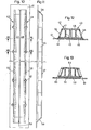
- FIG. 4 to 7 show the first embodiment of the formwork element in a front view and a side view, in each case a central region of the formwork element being omitted, and in the two sections VI-VI and VII-VII made clear in FIG. 4.
- Fig. 8 shows a perspective view, also with the omission of the central area, the end face of the wall section produced, the partially broken joint tape including the molded shoulder in the area of the lower sole plate is also shown.
- Fig. 9 shows a perspective view of the joint between two adjoining vand sections with the joint tape.
- Figures 10 to 13 show the second embodiment of the formwork element, again in front view, side view and in two characteristic sections indicated in Fig. 10.
- Figures 1 to 3 illustrate the operation in the manufacture of a diaphragm wall section.
- guide walls 1 and 2 are set in a known manner, which protrude, for example, approximately 1.5 m deep into the ground and determine the width of the slot to be excavated and thus the slot wall thickness.
- the arrangement of the upper edge 3 of the guide walls 1 and 2 in alignment with the surface 4 of the soil 5 can be seen from the figures.
- Fig. 1 is based on a concrete wall section 6 with a not yet drawn or raised formwork element 7.
- a subsequent slot section 8 is excavated in a known manner.
- the back of the formwork element is cleaned by lowering a tool 10 with chisels 11, which is already known for crushing the earth material to be excavated, into the slot section 8.
- This tool 10 has been equipped with toothed strips 12 which chisel off the concrete 13 adhering to the rear of the formwork element 7.
- the tool 10 is provided with an inclined run-up surface 14 which, in accordance with the force decomposition indicated by arrows, ensures that the toothed strips 12 are pressed against the smooth rear side of the formwork element 7.
- the formwork element 7 After cleaning the back of the formwork element 7, this is pressed laterally into the slot section 8, as indicated in FIG. 2, which can be done in the manner described above and is not indicated in more detail.
- the formwork element 7 detaches from the joint tape 15 previously received in it, which, as indicated, is approximately half embedded in the wall section 6 that has already been produced. After the lateral pressing, the formwork element 7 is lifted out of the slot section 8.
- the mold member 7 is provided with a new joint tape 15 'and corresponding to FIG. 3 on the loading placed the re its concrete wall portion 6 facing away from the end of the slit section 8.
- a reinforcement cage is arranged in the slot section 8 in a known manner, whereupon it is filled with concrete in the contractor process.
- This concrete penetrates through the formwork element 7 or past its narrow longitudinal edges into the cavities 16 indicated in FIG. 3 on the back of the formwork element, as a result of which the concrete 13 shown in FIG. 1 and later demolished is formed.
- the formwork element according to Figures 4 to 7 consists of an elongated plate 21, from the front of which two stiffening rails 22 protrude, which extend parallel to one another, form a slot-shaped receptacle 23 for the joint tape 15 and have end faces 24 which are inclined in the longitudinal direction.
- the stiffening rails 22 are designed as a hollow profile with an inner leg 25 running perpendicular to the plate 21 and an inclined outer leg 26.
- the parts 21, 24, 25 and 26 are welded together.
- the end faces 24 and the outer legs 26 lead to a shape of the stiffening rails 22 that is conical in both the longitudinal and transverse directions.
- openings 27 are provided in the plate 21 at regular intervals in the longitudinal direction, which taper from the front to the rear of the plate 21.
- projections 28 are arranged on the outside of each stiffening rail, which in the transverse direction have inclined outer surfaces 29 and additionally inclined outer surfaces 30 in the longitudinal direction, which are each formed by welded sheet metal pieces and delimit closed cavities.
- the projections 28 are arranged in pairs next to one another and distributed over the length of the plate 21.
- the projections 28 are each arranged in the middle between the openings 27, which are likewise provided in pairs.
- FIG. 8 shows a finished wall section 32 made of concrete, which is also referred to as a lamella, and reveals the toothing recesses 33 which originate from the projections 2 8 of the formwork element.
- the stiffening rails 22 have also created a recess 34.
- the joint tape 15 can be seen, the freely projecting section 36 was received in the slot-shaped receptacle 23 of the formwork element. Also shown in the area of the not shown sole plate on the joint tape 15 is the projection 37, which seals against water penetrating in the vertical direction.
- FIG. 9 shows the wall section 32 with the adjoining wall section 38 and reveals the transverse toothing between the two wall sections and the position of the joint sealing tape 15, which is provided with a transverse flange 35 projecting on both sides.
- the second embodiment of the formwork element shown in FIGS. 10 to 13 has a plate 41 which has on its front side two stiffening members 42 and 43 which extend in the longitudinal direction and are designed and arranged symmetrically to the longitudinal center plane.
- the stiffening members 42 and 43 are releasably connected to the plate 41 by screws 44 (Figs. 12 & 12), so that the plate 41 can, if necessary, be exchanged for another plate of different widths.
- the stiffening members 42 and 43 each consist of a double T-beam 45 or 46, one flange of which rests on the plate 41 and the other flange of which forms a pressing surface 47 or 48 parallel to the plate.
- Inner surfaces 51, 52 are welded to the mutually adjacent inner ends of the flanges of the carriers 45 and 46, which form a receptacle 53 for the joint tape between them.
- the outer flanges of the supports 45 and 46 are partially shortened with an alternating inclination with respect to the longitudinal direction and with an inclination in the cross-sectional profile and are connected to one another at their outer ends by welded-in outer surfaces 55 and 56.
- stiffening members 42 and 43 are also provided at their ends with longitudinally inclined end faces 58 and 59, so that they form closed hollow profiles. Furthermore, pairs of openings 60 and 61 are provided on the outside of the stiffening members 42 and 43 in the area of their strongest constriction, which taper conically from the front to the rear of the plate 41.
- the plates 21 and 41 are provided, in a manner not shown but known, with connecting means in order to connect two or more formwork elements to one another on the end face and thereby to obtain a length corresponding to the diaphragm wall height.
Landscapes
- Engineering & Computer Science (AREA)
- Structural Engineering (AREA)
- Life Sciences & Earth Sciences (AREA)
- General Life Sciences & Earth Sciences (AREA)
- Mining & Mineral Resources (AREA)
- Paleontology (AREA)
- Civil Engineering (AREA)
- General Engineering & Computer Science (AREA)
- Forms Removed On Construction Sites Or Auxiliary Members Thereof (AREA)
- Road Paving Structures (AREA)
- Bulkheads Adapted To Foundation Construction (AREA)
Priority Applications (1)
| Application Number | Priority Date | Filing Date | Title |
|---|---|---|---|
| AT81107344T ATE14028T1 (de) | 1980-09-19 | 1981-09-17 | Verfahren und schalungselement zum herstellen von schlitzwaenden. |
Applications Claiming Priority (2)
| Application Number | Priority Date | Filing Date | Title |
|---|---|---|---|
| DE3035369A DE3035369C2 (de) | 1980-09-19 | 1980-09-19 | Verfahren und Schalungselement zum Herstellen von Schlitzwänden |
| DE3035369 | 1980-09-19 |
Publications (3)
| Publication Number | Publication Date |
|---|---|
| EP0048444A2 true EP0048444A2 (fr) | 1982-03-31 |
| EP0048444A3 EP0048444A3 (en) | 1982-06-09 |
| EP0048444B1 EP0048444B1 (fr) | 1985-06-26 |
Family
ID=6112365
Family Applications (1)
| Application Number | Title | Priority Date | Filing Date |
|---|---|---|---|
| EP81107344A Expired EP0048444B1 (fr) | 1980-09-19 | 1981-09-17 | Procédé et élément de coffrage pour la réalisation de parois moulées dans le sol |
Country Status (3)
| Country | Link |
|---|---|
| EP (1) | EP0048444B1 (fr) |
| AT (1) | ATE14028T1 (fr) |
| DE (2) | DE3035369C2 (fr) |
Cited By (6)
| Publication number | Priority date | Publication date | Assignee | Title |
|---|---|---|---|---|
| EP0462010A1 (fr) * | 1990-06-15 | 1991-12-18 | Bouygues | yispositif pour faciliter l'extraction d'un coffrage, et application à la réalisation d'une paroi moulée dans le sol. |
| FR2674888A1 (fr) * | 1991-04-02 | 1992-10-09 | Bouygues Sa | Dispositif pour faciliter l'extraction d'un coffrage, outil present dans le dispositif et application a la realisation d'une paroi moulee dans le sol. |
| DE19901556A1 (de) * | 1999-01-16 | 2000-08-03 | Brueckner Grundbau Gmbh | Vorrichtung und Verfahren zum Entfernen von Überbeton im Bereich einer Schlitzwandfuge |
| KR20030016030A (ko) * | 2001-08-20 | 2003-02-26 | 삼보건설기계 주식회사 | 기초공사용 콘크리트 타설공법 및 시일링장치 |
| CN116163319A (zh) * | 2023-02-20 | 2023-05-26 | 中国一冶集团有限公司 | 一种抗滑桩临空侧混凝土的处理方法 |
| EP4613937A1 (fr) * | 2024-03-07 | 2025-09-10 | BAUER Maschinen GmbH | Procédé de nettoyage d'un coffrage d'une paroi en béton dans le sol et dispositif de nettoyage |
Families Citing this family (1)
| Publication number | Priority date | Publication date | Assignee | Title |
|---|---|---|---|---|
| DE3404074A1 (de) * | 1984-02-06 | 1985-08-08 | Dyckerhoff & Widmann AG, 8000 München | Verfahren zum herstellen einer schlitzwand aus beton |
Family Cites Families (9)
| Publication number | Priority date | Publication date | Assignee | Title |
|---|---|---|---|---|
| FR1495550A (fr) * | 1967-12-20 | |||
| NL126150C (fr) * | 1964-11-11 | |||
| DE1634445A1 (de) * | 1966-11-08 | 1970-10-15 | Lorenz Dr Ing Hans | Verfahren zum Abdichten der senkrechten Arbeitsfugen einer im Untergrund herzustellenden Wand aus Beton oder Stahlbeton |
| US3564855A (en) * | 1968-04-08 | 1971-02-23 | Johann Morner | Method and device for making slit walls |
| DE1925025A1 (de) * | 1969-05-16 | 1970-11-26 | Holzmann Philipp Ag | Vorgefertigtes Bauglied zur Begrenzung von Schlitzwandabschnitten |
| DE2023372A1 (de) * | 1970-05-13 | 1971-12-02 | Morner, Johann, 8207 Endorf | Abdichtvornchtung zur Begrenzung von Betonierabschnitten bei der Herstellung von Schhtzwanden |
| BE785915A (fr) * | 1971-07-09 | 1973-01-08 | Sif Entreprise Bachy | Perfectionnement a l'execution des joints entre les panneaux successifsd'une paroi moulee dans le sol |
| FR2148706A5 (fr) * | 1971-07-30 | 1973-03-23 | Sif Entreprise Bachy | |
| CH614484A5 (en) * | 1977-07-05 | 1979-11-30 | Comar Reg Trust | Metal formwork element for the formation of vertical joints during the construction of cast walls |
-
1980
- 1980-09-19 DE DE3035369A patent/DE3035369C2/de not_active Expired
-
1981
- 1981-09-17 EP EP81107344A patent/EP0048444B1/fr not_active Expired
- 1981-09-17 AT AT81107344T patent/ATE14028T1/de not_active IP Right Cessation
- 1981-09-17 DE DE8181107344T patent/DE3171129D1/de not_active Expired
Cited By (8)
| Publication number | Priority date | Publication date | Assignee | Title |
|---|---|---|---|---|
| EP0462010A1 (fr) * | 1990-06-15 | 1991-12-18 | Bouygues | yispositif pour faciliter l'extraction d'un coffrage, et application à la réalisation d'une paroi moulée dans le sol. |
| FR2674888A1 (fr) * | 1991-04-02 | 1992-10-09 | Bouygues Sa | Dispositif pour faciliter l'extraction d'un coffrage, outil present dans le dispositif et application a la realisation d'une paroi moulee dans le sol. |
| DE19901556A1 (de) * | 1999-01-16 | 2000-08-03 | Brueckner Grundbau Gmbh | Vorrichtung und Verfahren zum Entfernen von Überbeton im Bereich einer Schlitzwandfuge |
| DE19901556B4 (de) * | 1999-01-16 | 2004-02-19 | Brückner Grundbau GmbH | Vorrichtung und Verfahren zum Entfernen von Überbeton im Bereich einer Schlitzwandfuge |
| KR20030016030A (ko) * | 2001-08-20 | 2003-02-26 | 삼보건설기계 주식회사 | 기초공사용 콘크리트 타설공법 및 시일링장치 |
| CN116163319A (zh) * | 2023-02-20 | 2023-05-26 | 中国一冶集团有限公司 | 一种抗滑桩临空侧混凝土的处理方法 |
| EP4613937A1 (fr) * | 2024-03-07 | 2025-09-10 | BAUER Maschinen GmbH | Procédé de nettoyage d'un coffrage d'une paroi en béton dans le sol et dispositif de nettoyage |
| WO2025186360A1 (fr) * | 2024-03-07 | 2025-09-12 | Bauer Maschinen Gmbh | Procédé de nettoyage d'un panneau de coffrage et engin de chantier doté d'un dispositif de nettoyage d'un panneau de coffrage |
Also Published As
| Publication number | Publication date |
|---|---|
| DE3171129D1 (en) | 1985-08-01 |
| EP0048444A3 (en) | 1982-06-09 |
| EP0048444B1 (fr) | 1985-06-26 |
| DE3035369C2 (de) | 1983-05-26 |
| ATE14028T1 (de) | 1985-07-15 |
| DE3035369A1 (de) | 1982-05-06 |
Similar Documents
| Publication | Publication Date | Title |
|---|---|---|
| DE2302053C3 (de) | Verbauvorrichtung für einen Leitungsgraben o.dgl. mit abgestuftem Querschnitt | |
| EP1146180B1 (fr) | Procédé pour la fabrication d'un élément de plancher en béton et élément de plancher en béton | |
| DE2944385A1 (de) | Verfahren zum herstellen von schlitzwaenden | |
| EP0475382B1 (fr) | Méthode et dispositif pour le boisement de fossés profonds | |
| DE2546946A1 (de) | Verfahren zum herstellen einer dichtungsschlitzwand im untergrund | |
| EP0048444A2 (fr) | Procédé et élément de coffrage pour la réalisation de parois moulées dans le sol | |
| DE4230533C2 (de) | Vorrichtung zum Austausch von Bodenmaterial, insbesondere neben Verkehrswegen und Bauwerken | |
| DE2616348C3 (de) | Vorrichtung für den Grabenverbau | |
| DE2847554C2 (de) | Fertiggarage o.dgl. aus Stahlbeton und Vorrichtung zu ihrer Herstellung | |
| DE2057263C3 (de) | Vorrichtung zum Abstützen von Grabenwänden | |
| DE60002936T2 (de) | Ausschalungshilfsvorrichtung | |
| EP1370730A1 (fr) | Panneau de construction pour le blindage de tranchees | |
| DE3001649C2 (de) | Verbauvorrichtung für Gräben | |
| DE19834476C1 (de) | Schalung und Verfahren zur Aufstellung | |
| AT314587B (de) | Einrichtung zur Durchführung eines Verfahrens zur unterirdischen Herstellung von Ortbetonkanälen und Stollen aller Art | |
| EP2369061A1 (fr) | Dispositif de coffrage pour le coffrage dans des tranchées | |
| DE4032646A1 (de) | Verfahren zum einbringen einer dichtwandmasse in den boden und verdraengerkoerper zur durchfuehrung des verfahrens | |
| DE2553002C3 (de) | Befahrbare Schalungschiene | |
| DE3320772A1 (de) | Verfahren zur herstellung von wandfoermigen bauwerken im erdreich und verdraengungskoerper zur durchfuehrung des verfahrens | |
| DE3610949A1 (de) | Verfahren zur herstellung einer schmalwand in erdboeden, sowie dazu dienende einrichtungen und elemente | |
| AT390290B (de) | Verfahren zur herstellung eines hangschutzbauwerkes sowie nach diesem verfahren hergestelltes hangschutzbauwerk | |
| DE3035033C2 (de) | Vorrichtung zur Herstellung von Beton-Schalungssteinen | |
| EP1193350A1 (fr) | Dispositif de blindage pour tranchées profondes | |
| DE8700410U1 (de) | Sicherheitsverbaukasten für Grabenaushub | |
| DE29502845U1 (de) | Stahlkassette für Montagegruben |
Legal Events
| Date | Code | Title | Description |
|---|---|---|---|
| PUAI | Public reference made under article 153(3) epc to a published international application that has entered the european phase |
Free format text: ORIGINAL CODE: 0009012 |
|
| AK | Designated contracting states |
Designated state(s): AT BE CH DE FR GB IT NL SE |
|
| PUAL | Search report despatched |
Free format text: ORIGINAL CODE: 0009013 |
|
| AK | Designated contracting states |
Designated state(s): AT BE CH DE FR GB IT NL SE |
|
| 17P | Request for examination filed |
Effective date: 19821206 |
|
| ITF | It: translation for a ep patent filed | ||
| GRAA | (expected) grant |
Free format text: ORIGINAL CODE: 0009210 |
|
| AK | Designated contracting states |
Designated state(s): AT BE CH DE FR GB IT LI NL SE |
|
| REF | Corresponds to: |
Ref document number: 14028 Country of ref document: AT Date of ref document: 19850715 Kind code of ref document: T |
|
| REF | Corresponds to: |
Ref document number: 3171129 Country of ref document: DE Date of ref document: 19850801 |
|
| ET | Fr: translation filed | ||
| PLBE | No opposition filed within time limit |
Free format text: ORIGINAL CODE: 0009261 |
|
| STAA | Information on the status of an ep patent application or granted ep patent |
Free format text: STATUS: NO OPPOSITION FILED WITHIN TIME LIMIT |
|
| 26N | No opposition filed | ||
| PG25 | Lapsed in a contracting state [announced via postgrant information from national office to epo] |
Ref country code: SE Effective date: 19890918 |
|
| PGFP | Annual fee paid to national office [announced via postgrant information from national office to epo] |
Ref country code: CH Payment date: 19900921 Year of fee payment: 10 |
|
| PG25 | Lapsed in a contracting state [announced via postgrant information from national office to epo] |
Ref country code: LI Effective date: 19910930 Ref country code: CH Effective date: 19910930 |
|
| REG | Reference to a national code |
Ref country code: CH Ref legal event code: PL |
|
| PGFP | Annual fee paid to national office [announced via postgrant information from national office to epo] |
Ref country code: GB Payment date: 19930827 Year of fee payment: 13 |
|
| PGFP | Annual fee paid to national office [announced via postgrant information from national office to epo] |
Ref country code: FR Payment date: 19930916 Year of fee payment: 13 |
|
| PG25 | Lapsed in a contracting state [announced via postgrant information from national office to epo] |
Ref country code: GB Effective date: 19940917 |
|
| EUG | Se: european patent has lapsed |
Ref document number: 81107344.4 Effective date: 19900521 |
|
| GBPC | Gb: european patent ceased through non-payment of renewal fee |
Effective date: 19940917 |
|
| PG25 | Lapsed in a contracting state [announced via postgrant information from national office to epo] |
Ref country code: FR Effective date: 19950531 |
|
| REG | Reference to a national code |
Ref country code: FR Ref legal event code: ST |
|
| PGFP | Annual fee paid to national office [announced via postgrant information from national office to epo] |
Ref country code: AT Payment date: 19960919 Year of fee payment: 16 |
|
| PGFP | Annual fee paid to national office [announced via postgrant information from national office to epo] |
Ref country code: BE Payment date: 19960920 Year of fee payment: 16 |
|
| PGFP | Annual fee paid to national office [announced via postgrant information from national office to epo] |
Ref country code: NL Payment date: 19960930 Year of fee payment: 16 |
|
| PGFP | Annual fee paid to national office [announced via postgrant information from national office to epo] |
Ref country code: DE Payment date: 19961104 Year of fee payment: 16 |
|
| PG25 | Lapsed in a contracting state [announced via postgrant information from national office to epo] |
Ref country code: AT Free format text: LAPSE BECAUSE OF NON-PAYMENT OF DUE FEES Effective date: 19970917 |
|
| PG25 | Lapsed in a contracting state [announced via postgrant information from national office to epo] |
Ref country code: BE Free format text: LAPSE BECAUSE OF NON-PAYMENT OF DUE FEES Effective date: 19970930 |
|
| BERE | Be: lapsed |
Owner name: PFODERL ROBERT Effective date: 19970930 |
|
| PG25 | Lapsed in a contracting state [announced via postgrant information from national office to epo] |
Ref country code: NL Free format text: LAPSE BECAUSE OF NON-PAYMENT OF DUE FEES Effective date: 19980401 |
|
| NLV4 | Nl: lapsed or anulled due to non-payment of the annual fee |
Effective date: 19980401 |
|
| PG25 | Lapsed in a contracting state [announced via postgrant information from national office to epo] |
Ref country code: DE Free format text: LAPSE BECAUSE OF NON-PAYMENT OF DUE FEES Effective date: 19980603 |