EP0048450B1 - Sicherheitseinrichtung für Maschinen mit sich hin- und herbewegenden Teilen - Google Patents
Sicherheitseinrichtung für Maschinen mit sich hin- und herbewegenden Teilen Download PDFInfo
- Publication number
- EP0048450B1 EP0048450B1 EP81107357A EP81107357A EP0048450B1 EP 0048450 B1 EP0048450 B1 EP 0048450B1 EP 81107357 A EP81107357 A EP 81107357A EP 81107357 A EP81107357 A EP 81107357A EP 0048450 B1 EP0048450 B1 EP 0048450B1
- Authority
- EP
- European Patent Office
- Prior art keywords
- plate cam
- sensor
- safety device
- frame
- stud
- Prior art date
- Legal status (The legal status is an assumption and is not a legal conclusion. Google has not performed a legal analysis and makes no representation as to the accuracy of the status listed.)
- Expired
Links
Images


Classifications
-
- F—MECHANICAL ENGINEERING; LIGHTING; HEATING; WEAPONS; BLASTING
- F16—ENGINEERING ELEMENTS AND UNITS; GENERAL MEASURES FOR PRODUCING AND MAINTAINING EFFECTIVE FUNCTIONING OF MACHINES OR INSTALLATIONS; THERMAL INSULATION IN GENERAL
- F16P—SAFETY DEVICES IN GENERAL; SAFETY DEVICES FOR PRESSES
- F16P3/00—Safety devices acting in conjunction with the control or operation of a machine; Control arrangements requiring the simultaneous use of two or more parts of the body
- F16P3/12—Safety devices acting in conjunction with the control or operation of a machine; Control arrangements requiring the simultaneous use of two or more parts of the body with means, e.g. feelers, which in case of the presence of a body part of a person in or near the danger zone influence the control or operation of the machine
- F16P3/16—Safety devices acting in conjunction with the control or operation of a machine; Control arrangements requiring the simultaneous use of two or more parts of the body with means, e.g. feelers, which in case of the presence of a body part of a person in or near the danger zone influence the control or operation of the machine with feeling members moved by the machine
Definitions
- This invention relates to a safety device used for an apparatus of the type having a frame, a stationary block fixed to the frame and a reciprocating member mounted on the frame, disposed above and in vertically opposed relation to the stationary block and adapted for forceful reciprocation thereto, such as presses, riveters, stakers, staplers and drills, which type of apparatus is hereinafter referred to as a "forceful reciprocation machine" for convenience's sake.
- a safety device of the species described in the preamble of the claim 1 is basically known already from FR-A-986 739.
- the connecting means allowing movement of the plate cam relative to the sensor is rather complicated.
- another intermediate plate with a bore for receiving a ball. This ball may be taken into engagement alternatively with a recess in the sensor or with a recess in the plate cam, so as to couple the respective components with each other.
- the invention therefore aims at improving the structure of the conventional safety device.
- the solution of this problem is stated in the characterizing clause of the claim 1.
- the safety device according to the present invention excels by a simple structure. For this reason, it can be manufactured at low cost, is easy to maintain and reliable in operation.
- the present invention is illustrated as being incorporated in a stapling machine used for application of hook and eye fastener parts to fabric of a garment, although the invention is versatile to forceful reciprocation machines of various types having a stationary block and a reciprocating member forcefully reciprocating thereto, such as for example, presses, riveters, stakers, staplers and drills.
- Reference numeral 10 broadly denotes a frame of the stapling machine which comprises a base 12, a standard 14fixed substantially upright thereto, a bed 16 mounted horizontally on the standard 14 and a transversely extending upright head plate 18 mounted on the bed 16.
- a ram (not shown) is mounted on the head plate 18 and adapted for vertical reciprocation by an air cylinder (not shown either).
- the ram is provided at its lower end with a fastener holder 20 designed in the shown embodiment for holding a hook part of a hook and eye fastener.
- Mounted on the horizontal bed 16 in vertically opposed relation to the fastener holder 20 is a die holder 22 within which a die (not shown) is embedded in vertical registration with the fastener holder 20.
- a working table 24 is horizontally mounted on the die holder 22 for convenience in manipulation by an operator of the garment fabric.
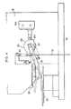
- Reference numeral 30 broadly denotes a safety device mounted on one side of the head 18 and disposed beside the reciprocating fastener holder 20, the detailed construction of which device is shown in Figures 2 and 3.
- a plate cam 32 assumes a substantially tear-drop shaped configuration, as projected upon the side surface of the head plate 18, and is pivotally mounted on the head plate 18 by a shaft 34 which is disposed adjacent to and rightward (as viewed in Figure 2) of the fastener holder 20.
- the plate cam 32 is provided in the peripheral surface thereof with an arcuate concave 35 of which function is described in detail hereinafter.
- An elongated rectangular sensor arm 36 is mounted at its one end pivotally and coaxially on the common shaft 34.
- a pin 38 is provided on the lower side of and intermediately of the rectangular sensor arm 36.
- a first tension spring 40 is connected between the pin 38 of the sensor arm 36 and a protuberant lug 42 provided on the lower part of the side surface of the plate cam 32, so that the sensor arm 36 is urged to angularly move counterclockwise (as viewed in Figure 2) relative to the plate cam 32 into abutting engagement with a protuberant peg 44 provided on the side surface of the plate cam and disposed slightly above the protuberant lug 42.
- the sensor arm 36 is provided intermediately and in the upper edge thereof with a rectangular indentation 46 which is disposed in confronting relation to a stud 48 provided on the apex or the left end (as viewed in Figure 2) of the tear-drop shaped plate cam 32. Therefore, the relative angular movement of the sensor arm 36 to the plate cam 32 is confined to a second angular range by the stud 48 and the peg 44.
- a sensor rod 50 Connected to the distal end of the sensor arm 36 is a sensor rod 50 terminating in a rectangular loop 52 which is arranged in surrounding relation to the vertical path along which the fastener holder 20 reciprocates.
- a bracket 54 has one of the legs thereof or a support leg 56 fixed to the head plate 18 upwardly of the sensor arm 36 and the other leg or the projecting leg 58 disposed over the sensor arm 36.
- the projecting leg 58 is provided with a through threaded hole (not shown) through which an adjustable screw 60 is screwed for abutting engagement with the sensor arm 30 so as to restrict clockwise angular movement of the sensor arm 36 and hence the plate cam 32. Therefore, the angular movement of the sensor arm 36 is confined to a first angular range by the working table 24 and the adjustable screw 60.
- a second tension spring 62 is connected between the stud 48 and a post 64 fixed to the support leg 56 of the bracket 54, thereby urging the plate cam 32 and hence sensor arm 36 as well in clockwise direction as viewed in Figure 2.
- a limit switch 66 which has a switch body 67, an actuating plunger 68 projected downwardly from the bottom thereof and resiliently supported thereby and a follower roller 70 rotatably mounted on the tip of the actuating plunger 68, so that the follower roller 70 is held in resilient and rolling engagement with the peripheral surface of the plate cam 32.
- the relative arrangement of the plate cam 32 and the limit switch 66 is such that only when the plate cam 32 is turned fully over the first and second angular ranges, the follower roller 70 is rolled into fitting engagement with the arcuate concave 35, whereupon the limit switch 66 activates the control circuit of operation of the air cylinder.
- a chain 72 Hanging from the stud 48 of the plate cam 32 is a chain 72 whose distal end is attached to the toe of a foot pedal 74 which is mounted on the base 12 for pivotal movement on an intermediate axis, as shown in Figure 1.
- the safety device 30 of the foregoing construction operates as follows. In preparation for operating the stapling machine, a fastener 80 (a hook part of a hook and eye fastener as shown in this embodiment) is retained on the fastener holder 20 and fabric of a garment 82 is placed flat on the working table 24.
- a fastener 80 (a hook part of a hook and eye fastener as shown in this embodiment) is retained on the fastener holder 20 and fabric of a garment 82 is placed flat on the working table 24.
- the plate cam 32 Upon continued depression of the foot pedal 74, the plate cam 32 alone still keeps on turning counterclockwise over the second angular range against the combined biases of both first and second tension springs 62, 40 until the stud 48 of the plate cam 32 comes into abutting engagement with and is blocked by the indentation 46 of the sensor arm 36. At this very moment, the follower roller 70 of the switch 66 rolls into fitting engagement with the arcuate concave 35 of the plate cam 32, so that the limit switch 66 activates the control circuit (not shown) for actuation of the air cylinder, whereupon a downward stroke of the ram and hence the fastener holder 20 is provided.
- FIG 4 illustrates another embodiment of the present invention which is substantially identical to the preceding embodiment with the exception that a plate cam 100 has a convex 102 instead of a concave 35 provided on the peripheral surface thereof and disposed diametrically opposite to the apex thereof, and a switch 104 is accordingly placed on the right side (as viewed in Figure 4) of the plate cam 100.
- This embodiment is intended to show substitutability of the convex for the concave 35 of the preceding embodiment and adaptability of the switch 66, 104 to various locations surrounding the plate cam 32, 100.
- the stapling machine even if the foot pedal 74 is depressed in full stroke while a finger of the operator or any extraneous thing accidentally lie between the garment fabric 82 and the loop 52 of the sensor rod 50, the stapling machine nevertheless will not start to work with assurance, since, as long as the sensor rod 36 is obstructed by the obstacle, a further turn of the plate cam 32 would cause the stud 48 to come into abutting engagement with and to be blocked by the indentation 46 of the sensor arm 36 before the follower roller 70 rolls into fitting engagement with the concave 35 of the peripheral surface of the plate cam 32, with the result that the finger of the operator or the extraneous thing is completely prevented from being hurt or damaged by the downward stroke of the fastener holder 20.
- the impact on an operator's finger exerted by the sensor rod 50 is reduced to minimum since being absorbed by the first tension spring 40, so that this safety device will cause no such fear on even novices or female workers.
- the switch roll 70 is held in resilient and rolling engagement with the peripheral surface of the plate cam 32 so as to be brought into and out of engagement with the deflection 35 in response to the angular movement of the plate cam 32, so that the switch roll 70 and the deflection 35 are subjected to a small impact when mutually engaged.
- the safety device as a whole is so flexible in shape as to be installed in a remaining small space of any contour defined by a crowd of components mounted on the forceful reciprocation machine.
Landscapes
- Engineering & Computer Science (AREA)
- General Engineering & Computer Science (AREA)
- Mechanical Engineering (AREA)
- Sewing Machines And Sewing (AREA)
- Portable Nailing Machines And Staplers (AREA)
- A Measuring Device Byusing Mechanical Method (AREA)
- Rotary Switch, Piano Key Switch, And Lever Switch (AREA)
Claims (8)
Applications Claiming Priority (2)
| Application Number | Priority Date | Filing Date | Title |
|---|---|---|---|
| JP133440/80 | 1980-09-19 | ||
| JP1980133440U JPS5812812Y2 (ja) | 1980-09-19 | 1980-09-19 | 留具取付機における安全装置 |
Publications (3)
| Publication Number | Publication Date |
|---|---|
| EP0048450A2 EP0048450A2 (de) | 1982-03-31 |
| EP0048450A3 EP0048450A3 (en) | 1983-01-19 |
| EP0048450B1 true EP0048450B1 (de) | 1985-12-11 |
Family
ID=15104816
Family Applications (1)
| Application Number | Title | Priority Date | Filing Date |
|---|---|---|---|
| EP81107357A Expired EP0048450B1 (de) | 1980-09-19 | 1981-09-17 | Sicherheitseinrichtung für Maschinen mit sich hin- und herbewegenden Teilen |
Country Status (7)
| Country | Link |
|---|---|
| US (1) | US4420071A (de) |
| EP (1) | EP0048450B1 (de) |
| JP (1) | JPS5812812Y2 (de) |
| AU (1) | AU530766B2 (de) |
| CA (1) | CA1173201A (de) |
| DE (1) | DE3173205D1 (de) |
| ES (1) | ES8300990A1 (de) |
Families Citing this family (5)
| Publication number | Priority date | Publication date | Assignee | Title |
|---|---|---|---|---|
| JPH02132622U (de) * | 1989-04-04 | 1990-11-05 | ||
| DE19700524C1 (de) * | 1997-01-09 | 1998-10-01 | Ykk Corp | Vorrichtung zum Ansetzen von Nieten, Knöpfen oder dergleichen an eine Textilie |
| US6948224B2 (en) * | 2003-05-02 | 2005-09-27 | Gradco (Japan) Ltd | Automatic stapling method and stapler |
| CN102367008B (zh) * | 2011-09-17 | 2014-05-14 | 陈浩波 | 往复式压力机设备后退式安全保护系统 |
| CN104287263B (zh) * | 2014-09-28 | 2016-05-18 | 刘明亮 | 自动安全型碑机 |
Family Cites Families (13)
| Publication number | Priority date | Publication date | Assignee | Title |
|---|---|---|---|---|
| US1084897A (en) * | 1912-09-18 | 1914-01-20 | Pritchard Stamping Company | Guard for machinery. |
| US1282452A (en) * | 1918-03-28 | 1918-10-22 | Thomas Alfred Mountford | Safety device for punch-presses. |
| US1370369A (en) * | 1918-04-26 | 1921-03-01 | Sherman W Scofield | Safety device for presses |
| US1346713A (en) * | 1919-10-01 | 1920-07-13 | Koetting August | Safety-guard for punch-presses |
| US1418525A (en) * | 1921-08-27 | 1922-06-06 | Michigan Mutual Liability Comp | Safety attachment for punch presses |
| US1500337A (en) * | 1922-03-30 | 1924-07-08 | Aetna Life Insurance Company | Punch-press guard mechanism |
| US1525645A (en) * | 1923-08-25 | 1925-02-10 | Franz A Fuller | Press guard |
| FR778252A (fr) * | 1934-09-11 | 1935-03-13 | Dispositif de sécurité pour presses et machines analogues et machines munies de cedispositif | |
| GB530212A (en) * | 1939-06-30 | 1940-12-06 | John Hastings | Improvements in guards for presses and the like |
| FR986739A (fr) * | 1949-03-17 | 1951-08-03 | Appareil de sécurité destiné, notamment, aux presses à découper ou emboutir | |
| GB683413A (en) * | 1950-02-24 | 1952-11-26 | Washers Ltd | Improvements in press guards for hand-operated presses |
| FR1203851A (fr) * | 1958-04-30 | 1960-01-21 | Anciens Etablissements Lapipe | Appareil de sécurité à volet de commande pneumatique pour presses à embrayage à clavette tournante |
| US3292837A (en) * | 1965-03-19 | 1966-12-20 | North And Judd Mfg Company | Stapling machine |
-
1980
- 1980-09-19 JP JP1980133440U patent/JPS5812812Y2/ja not_active Expired
-
1981
- 1981-09-07 AU AU74979/81A patent/AU530766B2/en not_active Ceased
- 1981-09-16 ES ES81505522A patent/ES8300990A1/es not_active Expired
- 1981-09-17 EP EP81107357A patent/EP0048450B1/de not_active Expired
- 1981-09-17 DE DE8181107357T patent/DE3173205D1/de not_active Expired
- 1981-09-18 CA CA000386240A patent/CA1173201A/en not_active Expired
- 1981-09-21 US US06/303,929 patent/US4420071A/en not_active Expired - Fee Related
Also Published As
| Publication number | Publication date |
|---|---|
| DE3173205D1 (en) | 1986-01-23 |
| US4420071A (en) | 1983-12-13 |
| AU7497981A (en) | 1982-03-25 |
| EP0048450A3 (en) | 1983-01-19 |
| JPS5756719U (de) | 1982-04-02 |
| ES505522A0 (es) | 1982-12-01 |
| ES8300990A1 (es) | 1982-12-01 |
| JPS5812812Y2 (ja) | 1983-03-11 |
| CA1173201A (en) | 1984-08-28 |
| AU530766B2 (en) | 1983-07-28 |
| EP0048450A2 (de) | 1982-03-31 |
Similar Documents
| Publication | Publication Date | Title |
|---|---|---|
| US4436238A (en) | Apparatus for attaching fastener elements onto a garment | |
| US4363281A (en) | Sewing-machine system for continuously monitoring workpiece thickness | |
| EP0048450B1 (de) | Sicherheitseinrichtung für Maschinen mit sich hin- und herbewegenden Teilen | |
| CA1251021A (en) | Apparatus for assembling a pair of fastener elements | |
| KR900008289B1 (ko) | 재봉물 지지 장치를 가진 재봉틀 및 그 재봉 방법 | |
| US4058071A (en) | Sewing machine presser bar mechanism | |
| US4505213A (en) | Stitch length control for hand operable sewing machine | |
| US4067275A (en) | Device for sewing machines for displacing sewn material for a short period of time | |
| US4674424A (en) | Presser foot lifting mechanism | |
| JPS59101189A (ja) | ミシンの布押え装置 | |
| US4114546A (en) | Sewing machine with a workpiece guide mechanism | |
| JPS6136956B2 (de) | ||
| US4522135A (en) | Looper and cam assembly for chain stitch sewing machine | |
| CN211747250U (zh) | 一种大白扣机 | |
| JPH05153Y2 (de) | ||
| US4535711A (en) | Looper-cam shifting arrangement for a sewing machine | |
| JPS6320153B2 (de) | ||
| US4777893A (en) | Presser foot assembly | |
| JPS6349268Y2 (de) | ||
| KR860000110B1 (ko) | 파워 프레스의 안전장치 | |
| JPS6221271Y2 (de) | ||
| TWM630671U (zh) | 縫紉機的送布齒輪抬升機構 | |
| JPS6232554Y2 (de) | ||
| JPH0736633Y2 (ja) | ミシンの布制御装置 | |
| JPH0152036B2 (de) |
Legal Events
| Date | Code | Title | Description |
|---|---|---|---|
| PUAI | Public reference made under article 153(3) epc to a published international application that has entered the european phase |
Free format text: ORIGINAL CODE: 0009012 |
|
| AK | Designated contracting states |
Designated state(s): BE DE FR GB IT |
|
| ITCL | It: translation for ep claims filed |
Representative=s name: JACOBACCI CASETTA & PERANI S.P.A. |
|
| DET | De: translation of patent claims | ||
| PUAL | Search report despatched |
Free format text: ORIGINAL CODE: 0009013 |
|
| AK | Designated contracting states |
Designated state(s): BE DE FR GB IT |
|
| 17P | Request for examination filed |
Effective date: 19830427 |
|
| ITF | It: translation for a ep patent filed | ||
| GRAA | (expected) grant |
Free format text: ORIGINAL CODE: 0009210 |
|
| AK | Designated contracting states |
Designated state(s): BE DE FR GB IT |
|
| ET | Fr: translation filed | ||
| REF | Corresponds to: |
Ref document number: 3173205 Country of ref document: DE Date of ref document: 19860123 |
|
| PLBE | No opposition filed within time limit |
Free format text: ORIGINAL CODE: 0009261 |
|
| STAA | Information on the status of an ep patent application or granted ep patent |
Free format text: STATUS: NO OPPOSITION FILED WITHIN TIME LIMIT |
|
| 26N | No opposition filed | ||
| GBPC | Gb: european patent ceased through non-payment of renewal fee | ||
| PG25 | Lapsed in a contracting state [announced via postgrant information from national office to epo] |
Ref country code: BE Effective date: 19870930 |
|
| BERE | Be: lapsed |
Owner name: YOSHIDA KOGYO K.K. Effective date: 19870930 |
|
| PG25 | Lapsed in a contracting state [announced via postgrant information from national office to epo] |
Ref country code: FR Free format text: LAPSE BECAUSE OF NON-PAYMENT OF DUE FEES Effective date: 19880531 |
|
| PG25 | Lapsed in a contracting state [announced via postgrant information from national office to epo] |
Ref country code: DE Effective date: 19880601 |
|
| REG | Reference to a national code |
Ref country code: FR Ref legal event code: ST |
|
| PG25 | Lapsed in a contracting state [announced via postgrant information from national office to epo] |
Ref country code: GB Effective date: 19881118 |