EP0048458A2 - Ensemble porte-outil, broche pour une machine-outil et méthode de sa fabrication - Google Patents
Ensemble porte-outil, broche pour une machine-outil et méthode de sa fabrication Download PDFInfo
- Publication number
- EP0048458A2 EP0048458A2 EP81107376A EP81107376A EP0048458A2 EP 0048458 A2 EP0048458 A2 EP 0048458A2 EP 81107376 A EP81107376 A EP 81107376A EP 81107376 A EP81107376 A EP 81107376A EP 0048458 A2 EP0048458 A2 EP 0048458A2
- Authority
- EP
- European Patent Office
- Prior art keywords
- chuck
- cups
- tool holder
- face
- balls
- Prior art date
- Legal status (The legal status is an assumption and is not a legal conclusion. Google has not performed a legal analysis and makes no representation as to the accuracy of the status listed.)
- Withdrawn
Links
- 238000004519 manufacturing process Methods 0.000 title abstract description 6
- 238000003754 machining Methods 0.000 claims abstract description 8
- 230000006835 compression Effects 0.000 claims description 11
- 238000007906 compression Methods 0.000 claims description 11
- 238000005266 casting Methods 0.000 claims description 8
- 239000011347 resin Substances 0.000 claims description 8
- 229920005989 resin Polymers 0.000 claims description 8
- 238000009760 electrical discharge machining Methods 0.000 claims description 7
- 238000000034 method Methods 0.000 claims description 7
- 150000001875 compounds Chemical class 0.000 claims description 5
- 239000011344 liquid material Substances 0.000 claims description 4
- 238000007711 solidification Methods 0.000 claims 1
- 230000008023 solidification Effects 0.000 claims 1
- 238000010276 construction Methods 0.000 abstract 1
- 229910000831 Steel Inorganic materials 0.000 description 2
- 238000005520 cutting process Methods 0.000 description 2
- 238000005553 drilling Methods 0.000 description 2
- 238000003801 milling Methods 0.000 description 2
- 239000010959 steel Substances 0.000 description 2
- 229910000760 Hardened steel Inorganic materials 0.000 description 1
- 238000013459 approach Methods 0.000 description 1
- 238000000227 grinding Methods 0.000 description 1
- 239000000463 material Substances 0.000 description 1
- 230000002093 peripheral effect Effects 0.000 description 1
- 238000004382 potting Methods 0.000 description 1
- 229910000679 solder Inorganic materials 0.000 description 1
- 230000002381 testicular Effects 0.000 description 1
Images


Classifications
-
- B—PERFORMING OPERATIONS; TRANSPORTING
- B23—MACHINE TOOLS; METAL-WORKING NOT OTHERWISE PROVIDED FOR
- B23Q—DETAILS, COMPONENTS, OR ACCESSORIES FOR MACHINE TOOLS, e.g. ARRANGEMENTS FOR COPYING OR CONTROLLING; MACHINE TOOLS IN GENERAL CHARACTERISED BY THE CONSTRUCTION OF PARTICULAR DETAILS OR COMPONENTS; COMBINATIONS OR ASSOCIATIONS OF METAL-WORKING MACHINES, NOT DIRECTED TO A PARTICULAR RESULT
- B23Q16/00—Equipment for precise positioning of tool or work into particular locations not otherwise provided for
- B23Q16/02—Indexing equipment
- B23Q16/08—Indexing equipment having means for clamping the relatively movable parts together in the indexed position
-
- B—PERFORMING OPERATIONS; TRANSPORTING
- B23—MACHINE TOOLS; METAL-WORKING NOT OTHERWISE PROVIDED FOR
- B23Q—DETAILS, COMPONENTS, OR ACCESSORIES FOR MACHINE TOOLS, e.g. ARRANGEMENTS FOR COPYING OR CONTROLLING; MACHINE TOOLS IN GENERAL CHARACTERISED BY THE CONSTRUCTION OF PARTICULAR DETAILS OR COMPONENTS; COMBINATIONS OR ASSOCIATIONS OF METAL-WORKING MACHINES, NOT DIRECTED TO A PARTICULAR RESULT
- B23Q3/00—Devices holding, supporting, or positioning work or tools, of a kind normally removable from the machine
- B23Q3/12—Devices holding, supporting, or positioning work or tools, of a kind normally removable from the machine for securing to a spindle in general
Definitions
- the invention relates to an arrangement of tool holder and spindle chuck for machine tools for machining workpieces. It is a combination of tool holder and spindle chuck.
- the tool holder in turn serves to receive a cutting tool that is either mechanically or hydraulically clamped, usually by means of its tool shaft, which is inserted into the tool holder.
- the tool holder (with the tool) is in turn clamped mechanically on the spindle chuck with pliers or magnetically with a magnetic chuck - or also clamped on the table of a machine tool if the tool is to be machined.
- Pairings of this type are used in tool changing devices for automatic tool change in the course of scheduled machining operations, preferably in the machining of workpieces by milling, drilling, spark eroding and the like.
- the change times and processes are controlled by means of paper tape or magnetic tape. Since the machines carry out their program unattended, spark erosion machines e.g. run through even during the night, very high demands are made on the changing device with regard to the adherence to very narrow positional tolerances of the tools on the spindle and the trouble-free change,
- the invention has for its object to find a pair of tool holder and spindle chuck that is self-centering, simple and robust in its structure and therefore maintenance-free, allows easy multiplication (copying) and with the tool change and handover can be performed between a magazine and the spindle with simple, translational and rotational movements.
- This object is achieved according to the invention with an arrangement in which the clamped tool holder rests with its bottom surface on the end face of the spindle chuck at three points and is centered in relation to the end face, at which hemispheres protrude above the end face and these receiving recesses in the floor area.
- Centering is understood here to mean the alignment of the holder in the normal to the face of the chuck (aligned with the spindle axis) and in height and in azimuth (at an angle lying in the face) to the face,
- the self-centering takes place in a sliding movement of the hemispheres on the walls of the recesses receiving them when the holder approaches the chuck.
- a three-point bearing results in a perfect fit in any case, since three points can always be used to lay a plane.
- the three hemispheres and spherical seats are easy to monitor and keep clean.
- the invention thus enables very simple, automatically working tool changing devices with which. Change the balls and their seats only have to be approximately aligned - in contrast to known systems for fixing the position of the tool holder on the chuck, which work with lateral stop surfaces and / or dowel pins.
- the use of hardened steel balls with the smallest diameter tolerances alone is not a guarantee of a finely tolerated position fixation with full interchangeability between tool holders and chucks.
- This also requires a suitable arrangement of the balls and recesses in the surfaces that come into contact with each other.
- the balls are arranged and held in cups which are inserted and cast into recesses in the spindle chuck, while the cups are formed in cups which are inserted and cast into the recess of the tool holder. In this way, an exact position fixation can be achieved on the three contact points during manufacture, which preferably lie on the corners of an equilateral triangle,
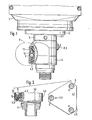
- Fig. 1 shows a side view of the quill head 1 of a spark erosion machine.
- a chuck 3 On the sleeve 2 there is a chuck 3, which is centered with a short taper 3.1 and with a reference surface 3.2 (FIG. 3) to a stop bar 2.1 on the sleeve 2 according to height and azimuth (at an angle).
- a holder 4 is seated on the chuck 3, in which the shaft of an electrode (not shown) is received in a known manner (not shown) and held by mechanical or hydraulic clamping.
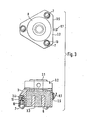
- Fig. 2 shows the holder 4 with a view of its bottom surface 4.1, in which three conical cups, 5 and three threaded blind holes 4.2 are incorporated in two circles concentric to the holder axis Z-Z at central angles of 120 degrees.
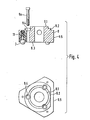
- Fig. 3 shows the chuck 3 with its end face 3.3, from which three steel balls 7 protrude as hemispheres on a circle concentric to the chuck axis Z-Z.
- the 'chuck is a magnetic chuck with an electromagnet 8, the circuit of which is led out to sliding contacts 8.1. You can also see the reference surface ..3.2 to the stop bar 2.1 on the. Quill (Fig. 1) and the short cone 3.1.
- Fig. 4 shows another chuck 9, with which a holder 4 is mechanically clamped, by means of three screws 9a, which are screwed through the holes 9.4 into the threaded blind holes 4.2 of the holder.
- the centering balls 7 protrude again from the end face 9.3 as hemispheres.
- This chuck 9 can in turn be picked up by a quill 2 with its short taper 9.1 and the reference surface 9.2.
- an electrode it is preferably clamped in a corresponding clamping device on the table of a machine tool.
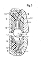
- a preferred embodiment of the three-point centering of an electrode (tool) holder 4 on a chuck 3 or 9 is shown in longitudinal section in the arrangement in FIG. 1 and in the constructive embodiment on an enlarged scale in FIG. 5.
- the balls 7 belonging to the chuck 3 or 9 are arranged in cups 10 and held by means of bolts 7.1 which are cast in and which are cast into recesses 11.
- a compression spring 12 is arranged between the bottoms of bowl 10 and recess 11.
- the casting compound preferably a casting resin
- the bowl 10 has a conical receptacle for the ball 7, on which it rests on a circle.
- the cups 5 are worked out as seats for the balls 7 protruding as hemispheres in cups 13, which are cast into recesses 14.
- a compression spring 15 is again arranged between the bottoms of the bowl 13 and the recess 14.
- the potting compound has been filled through a filling opening 4.3.
- An essential component is a teaching chuck 20 (FIG. 6), the body of which - shaped in the example as a cylinder section - has two plane-parallel end faces 20.1, 20.2 and again a reference face 20.3 according to the dimension of the reference. boundary surfaces 3.2 or 9.2 on the chucks 3 or 9 or according to the distance dimension of the stop bar 2.1 on the sleeve 2 (Fig. 1).
- the end face 20.1 three conical cups 5 are precisely incorporated as a master for the cups 5 in the holders 4.
- the body opens through axially parallel holes 20.4.
- the procedure for producing a holder 4 is similar, except that 20 balls 7 with bolts 7.1 are inserted into the holes 20.4 beforehand in the wells 5 of the teaching chuck. These balls protrude from the end face 20.1 as hemispheres.
- the teaching chuck is placed on a holder 4 and with this by means of the centering surfaces 4.5, 20.5 in of the above-mentioned device are exactly centered on one another, the cups 13, which can move with play in the recesses 14, adjust precisely to the balls 5 under the pressure of the springs i5. They are held in their position by a cast resin filled in at 4.3 after it has solidified in the position they are in.
- any number of holders and chucks can be produced in this way. It can be seen that after tensioning a holder on the chuck, the balls sit in their cups 5 without pressure. Axial clamping pressures are taken up between the end face 3.3 or 9.3 of a chuck 3 or 9 and the bottom face 4.1 of a holder 4. However, there is also the possibility, if necessary, of resetting the contact surfaces of the feed and holder after the casting compound has solidified by grinding if the cups 10, 13 are made of a correspondingly hard material.
- the embodiment of the invention shown as an example can be modified in details, in particular what the application of the contact pressure of the balls or cups during the clamping with the teaching chuck by different types of springs and the fixing of the bowls in their recesses, e.g. B. by means of solder rings.
- the design of the teaching chuck 20 and the means for centering with the duplicates, which are not essential for the invention, are not limited to the example of FIG. 6.
- FIG. 7 shows an alternative embodiment of the invention, in which each ball 7 is anchored in the associated bowl 10 in a particularly simple manner.
- the ball 7 is provided with an axial bore 7.3 and the associated bowl 10 has a threaded blind hole 10.1.
- a bolt 7.2 is inserted into the bore 7.3 and screwed into the threaded blind hole 10.1 and anchored there in a manner that is not shown.
- the execution 'form according to Figure 5 of the invention is the ball 7 on to a peripheral circuit in the receiving cone of the cup 10.3 10th
Landscapes
- Engineering & Computer Science (AREA)
- Mechanical Engineering (AREA)
- Jigs For Machine Tools (AREA)
- Automatic Tool Replacement In Machine Tools (AREA)
- Electrical Discharge Machining, Electrochemical Machining, And Combined Machining (AREA)
Applications Claiming Priority (2)
| Application Number | Priority Date | Filing Date | Title |
|---|---|---|---|
| DE3035229 | 1980-09-18 | ||
| DE19803035229 DE3035229A1 (de) | 1980-09-18 | 1980-09-18 | Anordnung aus werkzeughalter und spindel-spannfutter fuer werkzeugmaschinen und kopierverfahren zur herstellung |
Publications (2)
| Publication Number | Publication Date |
|---|---|
| EP0048458A2 true EP0048458A2 (fr) | 1982-03-31 |
| EP0048458A3 EP0048458A3 (fr) | 1983-04-20 |
Family
ID=6112285
Family Applications (1)
| Application Number | Title | Priority Date | Filing Date |
|---|---|---|---|
| EP81107376A Withdrawn EP0048458A3 (fr) | 1980-09-18 | 1981-09-17 | Ensemble porte-outil, broche pour une machine-outil et méthode de sa fabrication |
Country Status (3)
| Country | Link |
|---|---|
| EP (1) | EP0048458A3 (fr) |
| JP (1) | JPS5783333A (fr) |
| DE (1) | DE3035229A1 (fr) |
Cited By (4)
| Publication number | Priority date | Publication date | Assignee | Title |
|---|---|---|---|---|
| DE3335022A1 (de) * | 1983-09-28 | 1985-04-11 | Herbert Walter Werkzeug- und Maschinenbau KG, 7239 Fluorn-Winzeln | Befestigungseinrichtung fuer werkzeuge an werkzeugmaschinen |
| WO1988010172A1 (fr) * | 1987-06-23 | 1988-12-29 | GEDIB Ingenieurbüro und Innovationsberatung GmbH | Agencement de positionnement et son utilisation |
| EP0555810A1 (fr) * | 1992-02-11 | 1993-08-18 | Günter Meywald | Dispositif pour le positionnement de deux éléments à joindre |
| NL9402125A (nl) * | 1994-12-13 | 1996-07-01 | Roell Maria Van Druten | Lensopspanning en opspanmethode. |
Families Citing this family (2)
| Publication number | Priority date | Publication date | Assignee | Title |
|---|---|---|---|---|
| CN100411795C (zh) * | 2004-05-13 | 2008-08-20 | 嘉昇机电工业股份有限公司 | 细孔放电加工机自动更换电极装置 |
| CN106141704B (zh) * | 2015-03-30 | 2019-04-09 | 中国有色(沈阳)冶金机械有限公司 | 一种重型落地车床变径筒体加工组合工装 |
Family Cites Families (10)
| Publication number | Priority date | Publication date | Assignee | Title |
|---|---|---|---|---|
| US2527871A (en) * | 1946-06-21 | 1950-10-31 | Harding F Bakewell | Toolholder |
| GB735351A (en) * | 1952-11-20 | 1955-08-17 | John Hellewell | Method of and means for locking co-acting members |
| US2908195A (en) * | 1958-01-20 | 1959-10-13 | Enco Mfg Co | Turret toolpost |
| US3091134A (en) * | 1961-12-07 | 1963-05-28 | Thompson Designs Inc | Indexing mechanism |
| US3264941A (en) * | 1965-05-11 | 1966-08-09 | Miraglia Louis | Precise repetitive positioning device |
| DE1652761A1 (de) * | 1968-03-13 | 1971-04-08 | Karl Haberkern | Drehbare Teilvorrichtung,insbesondere Rundschalttisch und Bauelement zur Herstellung einer solchen Teilvorrichtung |
| US3588989A (en) * | 1968-06-26 | 1971-06-29 | Giddings & Lewis | Precision locating means for machine tools and methods of construction |
| US3711105A (en) * | 1970-11-12 | 1973-01-16 | Eltee Inc | Tool holding system |
| DE2537146C3 (de) * | 1975-08-21 | 1980-05-14 | Hubert Dipl.-Ing. 5820 Gevelsberg Bald | Baueinheit aus zwei in eine Relativlage zu positionierenden Bauteilen |
| FR2357950A1 (fr) * | 1976-07-07 | 1978-02-03 | Thomson Csf | Dispositif rotatif de commutation mecanique pas a pas |
-
1980
- 1980-09-18 DE DE19803035229 patent/DE3035229A1/de not_active Withdrawn
-
1981
- 1981-09-17 EP EP81107376A patent/EP0048458A3/fr not_active Withdrawn
- 1981-09-17 JP JP14772981A patent/JPS5783333A/ja active Pending
Cited By (5)
| Publication number | Priority date | Publication date | Assignee | Title |
|---|---|---|---|---|
| DE3335022A1 (de) * | 1983-09-28 | 1985-04-11 | Herbert Walter Werkzeug- und Maschinenbau KG, 7239 Fluorn-Winzeln | Befestigungseinrichtung fuer werkzeuge an werkzeugmaschinen |
| WO1988010172A1 (fr) * | 1987-06-23 | 1988-12-29 | GEDIB Ingenieurbüro und Innovationsberatung GmbH | Agencement de positionnement et son utilisation |
| US5397231A (en) * | 1987-06-23 | 1995-03-14 | Bald; Hubert | Position assembly for use in assembling two components |
| EP0555810A1 (fr) * | 1992-02-11 | 1993-08-18 | Günter Meywald | Dispositif pour le positionnement de deux éléments à joindre |
| NL9402125A (nl) * | 1994-12-13 | 1996-07-01 | Roell Maria Van Druten | Lensopspanning en opspanmethode. |
Also Published As
| Publication number | Publication date |
|---|---|
| EP0048458A3 (fr) | 1983-04-20 |
| DE3035229A1 (de) | 1982-04-29 |
| JPS5783333A (en) | 1982-05-25 |
Similar Documents
| Publication | Publication Date | Title |
|---|---|---|
| DE3007440C2 (fr) | ||
| DE3003756C2 (de) | Einrichtung zur Halterung einer Elektrode für eine Funkenerosionsmaschine | |
| DE3308733A1 (de) | Praezisions-schnell-positioniermechanik und -verfahren | |
| DE1477140A1 (de) | Verfahren zum wegnehmbaren Befestigen eines Organs an einer Vorrichtung und Einrichtung zur Durchfuehrung dieses Verfahrens | |
| WO2002078898A1 (fr) | Dispositif pour fixer de façon amovible des pieces a usiner sur des dispositifs d'usinage | |
| DE4315839C2 (de) | Werkstückspannvorrichtung für Mehrseitenbearbeitung | |
| CH687673A5 (de) | Verfahren und Vorrichtung zur Herstellung eines Formteiles, insbesondere einer keramischen Zahnrestauration, sowie zur Herstellung von Sonotrodenkronen. | |
| EP0316552A2 (fr) | Dispositif pour usiner des trous à boulons ou à soupapes dans un disque ou une jante de roue d'un véhicule | |
| WO1988010172A1 (fr) | Agencement de positionnement et son utilisation | |
| EP0048458A2 (fr) | Ensemble porte-outil, broche pour une machine-outil et méthode de sa fabrication | |
| DE2632922A1 (de) | Anwendung einer positioniereinrichtung | |
| CH627107A5 (en) | Fastening device with allocated, non-rotating tool or tool holder with cylindrical shank | |
| DE4219905C2 (de) | Einwegläppwerkzeug zum Fertigbearbeiten einer Brillenglasoberfläche und als Halter verwendbarer Adapter | |
| DE2309332A1 (de) | Freitragende vorrichtung fuer werkzeugmaschinen zum selbsttaetigen spannen scheibenfoermiger werkstuecke | |
| DE3115586A1 (de) | Palettenarretiervorrichtung in einer werkzeugmaschine | |
| EP0775546A1 (fr) | Dispositif porte-outil | |
| DE2725655C3 (de) | Futter für einen zylindrischen Schaft aufweisende Werkzeuge bzw. Werkzeugeinsätze | |
| DE102022212346A1 (de) | Schleifvorrichtung | |
| DE2632435C2 (de) | Befestigungseinrichtung für Werkzeuge an Funkenerosionsmaschinen u.dgl. Werkzeugmaschinen | |
| DE3410670A1 (de) | Spannzeugwechselanordnung an werkzeugmaschinen | |
| DE2703332A1 (de) | Ausrichtvorrichtung fuer ein bearbeitungswerkzeug | |
| DE19514512C2 (de) | Einrichtung zum positionsdefinierten Aufspannen eines Werkstückes | |
| DE3222586C2 (fr) | ||
| CH624329A5 (en) | Method of clamping a workpiece in order to machine or inspect it, and clamping body for carrying out the method | |
| DE3643921A1 (de) | Verfahren zum feinbearbeiten von rotationssymmetrischen aussenflaechen an werkstuecken |
Legal Events
| Date | Code | Title | Description |
|---|---|---|---|
| PUAI | Public reference made under article 153(3) epc to a published international application that has entered the european phase |
Free format text: ORIGINAL CODE: 0009012 |
|
| AK | Designated contracting states |
Designated state(s): CH FR GB IT LI SE |
|
| PUAL | Search report despatched |
Free format text: ORIGINAL CODE: 0009013 |
|
| AK | Designated contracting states |
Designated state(s): CH FR GB IT LI SE |
|
| STAA | Information on the status of an ep patent application or granted ep patent |
Free format text: STATUS: THE APPLICATION IS DEEMED TO BE WITHDRAWN |
|
| 18D | Application deemed to be withdrawn |
Effective date: 19831221 |
|
| RIN1 | Information on inventor provided before grant (corrected) |
Inventor name: ZIMMER, ALFRED |