EP0048467A1 - Mehrteiliger Holzkörper, insbesondere für Möbel und Wände - Google Patents
Mehrteiliger Holzkörper, insbesondere für Möbel und Wände Download PDFInfo
- Publication number
- EP0048467A1 EP0048467A1 EP81107418A EP81107418A EP0048467A1 EP 0048467 A1 EP0048467 A1 EP 0048467A1 EP 81107418 A EP81107418 A EP 81107418A EP 81107418 A EP81107418 A EP 81107418A EP 0048467 A1 EP0048467 A1 EP 0048467A1
- Authority
- EP
- European Patent Office
- Prior art keywords
- wooden
- parts
- body according
- clamping member
- wooden body
- Prior art date
- Legal status (The legal status is an assumption and is not a legal conclusion. Google has not performed a legal analysis and makes no representation as to the accuracy of the status listed.)
- Granted
Links
- 239000002023 wood Substances 0.000 title claims description 8
- 230000008961 swelling Effects 0.000 claims abstract description 3
- 230000015572 biosynthetic process Effects 0.000 claims abstract 2
- 229920001971 elastomer Polymers 0.000 claims description 3
- 229920001821 foam rubber Polymers 0.000 claims description 3
- 229910000831 Steel Inorganic materials 0.000 claims description 2
- 239000000853 adhesive Substances 0.000 claims description 2
- 230000001070 adhesive effect Effects 0.000 claims description 2
- 239000002184 metal Substances 0.000 claims description 2
- 239000010959 steel Substances 0.000 claims description 2
- 239000013013 elastic material Substances 0.000 claims 1
- 230000008878 coupling Effects 0.000 abstract 4
- 238000010168 coupling process Methods 0.000 abstract 4
- 238000005859 coupling reaction Methods 0.000 abstract 4
- 238000010276 construction Methods 0.000 description 2
- 238000004519 manufacturing process Methods 0.000 description 2
- 239000002699 waste material Substances 0.000 description 2
- 241000167854 Bourreria succulenta Species 0.000 description 1
- 240000007049 Juglans regia Species 0.000 description 1
- 235000009496 Juglans regia Nutrition 0.000 description 1
- 241000219492 Quercus Species 0.000 description 1
- 235000016976 Quercus macrolepis Nutrition 0.000 description 1
- 206010042674 Swelling Diseases 0.000 description 1
- 238000012512 characterization method Methods 0.000 description 1
- 235000019693 cherries Nutrition 0.000 description 1
- 238000005336 cracking Methods 0.000 description 1
- 230000000694 effects Effects 0.000 description 1
- 238000005516 engineering process Methods 0.000 description 1
- 238000007789 sealing Methods 0.000 description 1
- IHQKEDIOMGYHEB-UHFFFAOYSA-M sodium dimethylarsinate Chemical class [Na+].C[As](C)([O-])=O IHQKEDIOMGYHEB-UHFFFAOYSA-M 0.000 description 1
- 235000020234 walnut Nutrition 0.000 description 1
Images
Classifications
-
- E—FIXED CONSTRUCTIONS
- E04—BUILDING
- E04F—FINISHING WORK ON BUILDINGS, e.g. STAIRS, FLOORS
- E04F13/00—Coverings or linings, e.g. for walls or ceilings
- E04F13/07—Coverings or linings, e.g. for walls or ceilings composed of covering or lining elements; Sub-structures therefor; Fastening means therefor
- E04F13/08—Coverings or linings, e.g. for walls or ceilings composed of covering or lining elements; Sub-structures therefor; Fastening means therefor composed of a plurality of similar covering or lining elements
- E04F13/0801—Separate fastening elements
-
- E—FIXED CONSTRUCTIONS
- E04—BUILDING
- E04F—FINISHING WORK ON BUILDINGS, e.g. STAIRS, FLOORS
- E04F13/00—Coverings or linings, e.g. for walls or ceilings
- E04F13/07—Coverings or linings, e.g. for walls or ceilings composed of covering or lining elements; Sub-structures therefor; Fastening means therefor
- E04F13/08—Coverings or linings, e.g. for walls or ceilings composed of covering or lining elements; Sub-structures therefor; Fastening means therefor composed of a plurality of similar covering or lining elements
- E04F13/10—Coverings or linings, e.g. for walls or ceilings composed of covering or lining elements; Sub-structures therefor; Fastening means therefor composed of a plurality of similar covering or lining elements of wood or with an outer layer of wood
-
- F—MECHANICAL ENGINEERING; LIGHTING; HEATING; WEAPONS; BLASTING
- F16—ENGINEERING ELEMENTS AND UNITS; GENERAL MEASURES FOR PRODUCING AND MAINTAINING EFFECTIVE FUNCTIONING OF MACHINES OR INSTALLATIONS; THERMAL INSULATION IN GENERAL
- F16B—DEVICES FOR FASTENING OR SECURING CONSTRUCTIONAL ELEMENTS OR MACHINE PARTS TOGETHER, e.g. NAILS, BOLTS, CIRCLIPS, CLAMPS, CLIPS OR WEDGES; JOINTS OR JOINTING
- F16B12/00—Jointing of furniture or the like, e.g. hidden from exterior
- F16B12/10—Jointing of furniture or the like, e.g. hidden from exterior using pegs, bolts, tenons, clamps, clips, or the like
- F16B12/12—Jointing of furniture or the like, e.g. hidden from exterior using pegs, bolts, tenons, clamps, clips, or the like for non-metal furniture parts, e.g. made of wood, of plastics
- F16B12/20—Jointing of furniture or the like, e.g. hidden from exterior using pegs, bolts, tenons, clamps, clips, or the like for non-metal furniture parts, e.g. made of wood, of plastics using clamps, clips, wedges, sliding bolts, or the like
-
- F—MECHANICAL ENGINEERING; LIGHTING; HEATING; WEAPONS; BLASTING
- F16—ENGINEERING ELEMENTS AND UNITS; GENERAL MEASURES FOR PRODUCING AND MAINTAINING EFFECTIVE FUNCTIONING OF MACHINES OR INSTALLATIONS; THERMAL INSULATION IN GENERAL
- F16B—DEVICES FOR FASTENING OR SECURING CONSTRUCTIONAL ELEMENTS OR MACHINE PARTS TOGETHER, e.g. NAILS, BOLTS, CIRCLIPS, CLAMPS, CLIPS OR WEDGES; JOINTS OR JOINTING
- F16B5/00—Joining sheets or plates, e.g. panels, to one another or to strips or bars parallel to them
- F16B5/0004—Joining sheets, plates or panels in abutting relationship
- F16B5/0056—Joining sheets, plates or panels in abutting relationship by moving the sheets, plates or panels or the interlocking key perpendicular to the main plane
- F16B5/006—Joining sheets, plates or panels in abutting relationship by moving the sheets, plates or panels or the interlocking key perpendicular to the main plane and using ring-shaped clamps
-
- F—MECHANICAL ENGINEERING; LIGHTING; HEATING; WEAPONS; BLASTING
- F16—ENGINEERING ELEMENTS AND UNITS; GENERAL MEASURES FOR PRODUCING AND MAINTAINING EFFECTIVE FUNCTIONING OF MACHINES OR INSTALLATIONS; THERMAL INSULATION IN GENERAL
- F16B—DEVICES FOR FASTENING OR SECURING CONSTRUCTIONAL ELEMENTS OR MACHINE PARTS TOGETHER, e.g. NAILS, BOLTS, CIRCLIPS, CLAMPS, CLIPS OR WEDGES; JOINTS OR JOINTING
- F16B5/00—Joining sheets or plates, e.g. panels, to one another or to strips or bars parallel to them
Definitions
- the present invention relates to a multi-part wooden body, in particular for furniture and walls, in which individual adjacent parts are connected so as to be displaceable relative to one another.
- the present invention aims to create a possibility to produce multi-part wooden bodies, in particular for furniture and walls, which are connected to one another in such a way that different shrinkage and swellings of these parts do not occur Creates cracks. This allows previous waste wood to be made usable for furniture and wall construction.
- Two board-shaped wooden parts 1 and 2 made of previous waste wood form part of a furniture wall 4.
- the two board-shaped wooden parts 1 and 2 - for other uses these parts do not need to be board-shaped - each have an abutting surface 6, 7, which define a joint 9 .
- a foam rubber band 10 provided with adhesive on both broad sides is inserted into this joint 9 and glued to the abutting surfaces 6 and 7.
- connection points 12 milled, which is limited on the inside by a full core 13.
- Core 13 and annular groove 12 are composed of two parts when two wooden parts are connected to one another. However, they are in three or more parts if three or more wooden parts are connected to one another at the connection point.
- the two wooden parts 1 and 2 are connected by means of an open clamping ring 15, which can be made of metal, in particular steel, or of rubber.
- a clamping ring 15 which is circular in cross section, it is also possible to use a, for example, longitudinally slotted clamping sleeve or sleeve. In any case, the clamping member is open so that it can be spread and pressed together.
- the core 13 is preferably circular cylindrical, as is the annular groove 12.
- the core 13 is less high than the annular groove 12 is deep, which, for example, allows a cover 17 with spring 18 to be inserted into the annular groove 12 in the manner shown in FIG. 2 and thus camouflage the connection point.
- the resilient connection given by the open clamping ring 15, allows the two wooden parts 1 and 2 to stretch in any direction without cracking, since the forces generated by the clamping member, ie the connecting ring 15 or one appropriate cuff. Since the width of the joint 9 can also change during these movements, but this should be tight, the foam rubber band is 10 - it can also be a corrugated rubber band, such as for sealing purposes is known to be used - introduced into the joint 9 and glued to the two abutting surfaces 6 and 7.
- annular groove 12 It is fundamentally possible to give the annular groove 12 a shape other than a circular cylindrical shape, but this is generally more complex in terms of production technology and cannot bring anything additional with respect to the connection. It is also possible to guide the wooden parts at least at one point by means of a pin, wherein the pin of one wooden part in the hole of the other can have a game corresponding to the shrinkage of the wood. However, it is also possible to design this connection as a fixed point, similar to the way it is carried out with foundations of steam turbines.
Landscapes
- Engineering & Computer Science (AREA)
- General Engineering & Computer Science (AREA)
- Architecture (AREA)
- Mechanical Engineering (AREA)
- Civil Engineering (AREA)
- Structural Engineering (AREA)
- Life Sciences & Earth Sciences (AREA)
- Wood Science & Technology (AREA)
- Furniture Connections (AREA)
- Connection Of Plates (AREA)
- Chemical And Physical Treatments For Wood And The Like (AREA)
- Dry Formation Of Fiberboard And The Like (AREA)
Abstract
Description
- Die vorliegende Erfindung betrifft einen mehrteiligen Holzkörper, insbesondere für Möbel und Wände, bei welchem einzelne benachbarte Teile relativ zueinander verschiebbar verbunden sind.
- Bei teuren Holzsorten, wie Nussbaum, Eiche, Kirschbaum u. dgl. Hölzer ist es betrüblich, feststellen zu müssen, dass deren Ausnützung, insbesondere im Möbelbau, schlecht ist. Dies ist unter anderem dadurch bedingt, dass die oberen Teile der Stämme und Astwerk meistens nur als Bauholz, Brennholz oder zur Herstellung von Spielwaren Verwendung finden, jedoch nicht für Möbel, Wohnwände u. dgl., insbesondere wegen ihren kleineren Dimensionen.
- Ein weiterer Grund, weshalb solche Teile meist nicht zusammengeleimt zur Verwendung gelangen, bildet das oft recht unterschiedliche Verhalten beim Schwinden und Schwellen oder Treiben des Holzes, welches bei derart verleimten Konstruktionen zu Rissen führen kann, eine in der Möbelindustrie gefürchtete Auswirkung.
- Die vorliegende Erfindung bezweckt die Schaffung einer Möglichkeit, mehrteilige Holzkörper, insbesondere für Möbel und Wände, herzustellen, welche derart miteinander verbunden sind, dass unterschiedliches Schwinden und Schwellen dieser Teile keine Risse erzeugt. Dies gestattet es, bisheriges Abfallholz für den Möbel- und Wandbau verwendbar zu gestalten.
- Diese Aufgabe löst der mehrteilige Holzkörper gemäss der Kennzeichnung des Anspruchs l.
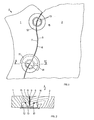
- Ein Ausführungsbeispiel des Erfindungsgegenstandes wird anschliessend anhand einer Zeichnung erläutert.
- Es zeigen:
- Fig. l eine Aufsicht auf einen Teil einer Möbelwand, mit zwei brettförmigen, federelastisch miteinander verbundenen Holzteilen,
- Fig. 2 einen Schnitt gemäss Schnittlinie II - II der Fig. l.
- Zwei aus bisherigem Abfallholz bestehende brettförmige Holzteile 1 und 2 bilden Teil einer Möbelwand 4. Die beiden brettförmigen Holzteile 1 und 2 - für einen anderen Gebrauch brauchen diese Teile nicht brettförmig zu sein - weisen je eine Stossfläche 6, 7 auf, die eine Fuge 9 festlegen. In diese Fuge 9 ist ein an beiden Breitseiten mit Klebstoff versehenes Schaumgummiband 10 eingelegt und mit den Stossflächen 6 und 7 verklebt.
- Um die beiden Holzteile 1 und 2 federnd miteinander zu verbinden, ist in diese an zwei (es können eine oder mehrere sein) Verbindungsstellen je eine Ringnut 12 eingefräst, welche innen durch einen vollen Kern 13 begrenzt ist. Kern 13 und Ringnut 12 setzen sich aus zwei Teilen zusammen, wenn zwei Holzteile miteinander verbunden werden. Sie sind indessen drei- oder mehrteilig, wenn drei und mehr Holzteile an der Verbindungsstelle miteinander verbunden werden. Die Verbindung der beiden Holzteile 1 und 2 erfolgt mittels eines offenen Klemmringes 15, welcher aus Metall, insbesondere Stahl, oder aus Gummi bestehen kann. Anstelle eines im Querschnitt kreisförmigen Klemmringes 15 kann auch eine, z.B. längsgeschlitzte Klemmanschette oder -hülse, verwendet werden. In jedem Fall ist das Klemmorgan offen, so dass es sich spreizen und zusammenpressen lässt.
- Der Kern 13 ist vorzugsweise kreiszylindrisch, ebenso die Ringnut 12. Der Kern 13 ist weniger hoch als die Ringnut 12 tief ist, was beispielsweise gestattet, einen Deckel 17 mit Feder 18 in die Ringnut 12, in der in Fig. 2 dargestellten Weise, einzuschieben und damit die Verbindungsstelle zu tarnen.
- Wenn nun das Holz schwindet oder anschwillt, gestattet die federnde Verbindung, gegeben durch den offenen Klemmring 15, dass die beiden Holzteile 1 und 2 sich in jeder Richtung ohne Rissbildung dehnen können, da die entstehenden Kräfte durch das Klemmorgan, d.h. den Verbindungsring 15 oder eine entsprechende Manschette, aufgenommen werden. Da bei diesen Bewegungen auch die Breite der Fuge 9 sich ändern kann, diese aber dicht sein soll, ist das Schaumgummiband 10 - es kann auch ein gewelltes Gummiband, wie dies zu Abdichtungszwecken bekannt ist, verwendet werden - in die Fuge 9 eingebracht und mit den beiden Stossflächen 6 und 7 verklebt.
- Es ist grundsätzlich möglich, der Ringnut 12 keine kreiszylindrische, sondern eine andere Gestalt zu geben, was aber herstellungstechnisch im allgemeinen aufwendiger ist und bezüglich Verbindung nichts Zusätzliches zu bringen vermag. Es ist ferner möglich, an mindestens einer Stelle die Holzteile mittels eines Zapfens zu führen, wobei der Zapfen des einen Holzteiles im Loch des anderen ein, den Schwindmassen des Holzes entsprechendes Spiel aufweisen kann. Es ist aber auch möglich, diese Verbindung als Festpunkt auszubilden, ähnlich wie dies bei Fundamenten von Dampfturbinen durchgeführt wird.
Claims (10)
- l. Mehrteiliger Holzkörper, insbesondere für Möbel und Wände, bei welchem einzelne benachbarte Teile relativ zueinander verschiebbar verbunden sind, dadurch gekennzeichnet, dass die Verbindung der Teile (1, 2) mindestens ein Klemmorgan (15) aufweist, das die beiden Teile (1, 2) federnd miteinander derart verbindet, dass ein Schwinden und Schwellen dieser Holzteile (1, 2) ohne Rissbildung sichergestellt ist.
- 2. Holzkörper nach Anspruch 1, dadurch gekennzeichnet, dass das Klemmorgan als offener Klemmring (15) oder als offene Manschette ausgebildet ist.
- 3. Holzkörper nach Anspruch 1, dadurch gekennzeichnet, dass die verbundenen, insbesondere zwei, Holzteile (1, 2) im Bereich des Klemmorganes (15) eine durch Stossfugen (9) getrennte Ausnehmung, insbesondere eine Nut, vorzugsweise eine zylindrische Ringnut (12) bilden, in welche das Klemmorgan (15) eingelegt ist.
- 4. Holzkörper nach Anspruch 3, dadurch gekennzeichnet, dass der mehrteilige, vorzugsweise kreiszylindrische Kern (13), einen dem Klemmorgan (15), vorzugsweise dem Ring, entsprechenden Umfang aufweist, derart, dass die Kraft des Klemmorganes (15) über den Kern (13) auf die Holzteile (1, 2) übertragen wird, um sie federnd miteinander zu verbinden,
- 5. Holzkörper nach Anspruch 3, dadurch gekennzeichnet, dass die Kernhöhe geringer ist als die Höhe der Ausnehmung (12).
- 6. Holzkörper nach Anspruch 1, dadurch gekennzeichnet, dass zum Abdecken der Verbindung ein Deckel (17, 18), vorzugsweise ein Klemmdeckel, vorgesehen ist.
- 7. Holzkörper nach Anspruch l, dadurch gekennzeichnet, dass eine Verbindungsstelle mindestens zwei Holzteile (1, 2) miteinander verbindet.
- 8. Holzkörper nach Anspruch 1, dadurch gekennzeichnet, dass das Klemmorgan (15) aus Metall, vorzugsweise aus Stahl oder Gummi, besteht.
- 9. Holzkörper nach Anspruch 1, dadurch gekennzeichnet, dass in den Trennfugen (9) zwischen den Holzteilen (1, 2) gummielastisches Material, vorzugsweise ein beidseitig klebendes Schaumgummiband (10),angeordnet ist.
- 10.Holzkörper nach Anspruch 1, dadurch gekennzeichnet, dass die Holzteile (1, 2) unter sich zusätzlich durch mindestens einen Zapfen in einer Bohrung, vorzugsweise mit den Holzbewegungen entsprechenden Spielen, verbunden sind.
Priority Applications (1)
| Application Number | Priority Date | Filing Date | Title |
|---|---|---|---|
| AT81107418T ATE13459T1 (de) | 1980-09-24 | 1981-09-18 | Mehrteiliger holzkoerper, insbesondere fuer moebel und waende. |
Applications Claiming Priority (2)
| Application Number | Priority Date | Filing Date | Title |
|---|---|---|---|
| CH7145/80A CH651778A5 (de) | 1980-09-24 | 1980-09-24 | Mehrteiliger holzkoerper, insbesondere fuer moebel und waende. |
| CH7145/80 | 1980-09-24 |
Publications (2)
| Publication Number | Publication Date |
|---|---|
| EP0048467A1 true EP0048467A1 (de) | 1982-03-31 |
| EP0048467B1 EP0048467B1 (de) | 1985-05-22 |
Family
ID=4320652
Family Applications (1)
| Application Number | Title | Priority Date | Filing Date |
|---|---|---|---|
| EP81107418A Expired EP0048467B1 (de) | 1980-09-24 | 1981-09-18 | Mehrteiliger Holzkörper, insbesondere für Möbel und Wände |
Country Status (4)
| Country | Link |
|---|---|
| EP (1) | EP0048467B1 (de) |
| AT (1) | ATE13459T1 (de) |
| CH (1) | CH651778A5 (de) |
| DE (1) | DE3170616D1 (de) |
Citations (3)
| Publication number | Priority date | Publication date | Assignee | Title |
|---|---|---|---|---|
| DE1934738A1 (de) * | 1969-07-09 | 1971-01-21 | Krupp Gmbh | Spannhuelsen-Verbindung |
| FR2082576A5 (de) * | 1970-03-20 | 1971-12-10 | Lacombe Raymond | |
| US3898012A (en) * | 1973-06-29 | 1975-08-05 | William Joseph Gillin | Separable fastener for parts of furniture |
Family Cites Families (1)
| Publication number | Priority date | Publication date | Assignee | Title |
|---|---|---|---|---|
| DE2846057A1 (de) * | 1978-10-23 | 1980-05-08 | Dichmann Ag Vario Werke | Koppeleinrichtung fuer raumgliederungselemente |
-
1980
- 1980-09-24 CH CH7145/80A patent/CH651778A5/de not_active IP Right Cessation
-
1981
- 1981-09-18 EP EP81107418A patent/EP0048467B1/de not_active Expired
- 1981-09-18 AT AT81107418T patent/ATE13459T1/de not_active IP Right Cessation
- 1981-09-18 DE DE8181107418T patent/DE3170616D1/de not_active Expired
Patent Citations (3)
| Publication number | Priority date | Publication date | Assignee | Title |
|---|---|---|---|---|
| DE1934738A1 (de) * | 1969-07-09 | 1971-01-21 | Krupp Gmbh | Spannhuelsen-Verbindung |
| FR2082576A5 (de) * | 1970-03-20 | 1971-12-10 | Lacombe Raymond | |
| US3898012A (en) * | 1973-06-29 | 1975-08-05 | William Joseph Gillin | Separable fastener for parts of furniture |
Also Published As
| Publication number | Publication date |
|---|---|
| CH651778A5 (de) | 1985-10-15 |
| EP0048467B1 (de) | 1985-05-22 |
| DE3170616D1 (en) | 1985-06-27 |
| ATE13459T1 (de) | 1985-06-15 |
Similar Documents
| Publication | Publication Date | Title |
|---|---|---|
| DE19715536A1 (de) | Griffgehäuse mit eingebautem Schalter und Verfahren zu dessen Herstellung | |
| DE3108197A1 (de) | Einsatz fuer eine verbundplatte | |
| DE8708667U1 (de) | Gerüstboden für ein Schnellbaugerüst | |
| DE4424671A1 (de) | Steuerspiegel einer hydraulischen Maschine | |
| AT405627B (de) | Vertikalverbindung zwischen zwei bauelementen | |
| EP0029904A2 (de) | Ringgedichtete Rohrsteckverbindung | |
| DE2903307A1 (de) | Transportpalette | |
| CH651778A5 (de) | Mehrteiliger holzkoerper, insbesondere fuer moebel und waende. | |
| DE2946509C2 (de) | Containerkupplung mit geteiltem Gehäuse | |
| EP0904872A1 (de) | Verbindung von Kernen | |
| EP0387192B1 (de) | Dammbalken | |
| EP0835978A2 (de) | Rahmen für Fenster, Türen, Fassaden oder dergl. | |
| DE609603C (de) | Insbesondere zur Herstellung von Massekernen aus Eisenpulver bestimmtes Pressgesenk | |
| DE2917468C2 (de) | Befestigungselement | |
| DE3408786C1 (de) | Verbindungselement zur unsichtbaren Verbindung von Teilen, insbesondere flächigen Teilen bei Möbeln | |
| DE3126346A1 (de) | Bergsteiger-klemmkeil | |
| DE1258674B (de) | Kreuzgelenkkupplung | |
| DE1037342B (de) | Bauspiel zum Bau von Fachwerkbauten | |
| DE2302457A1 (de) | Kettenschloss | |
| DE3044538C2 (de) | Hartfaserplatte | |
| DE573964C (de) | Gelenk, insbesondere fuer das Lenkgestaenge von Kraftfahrzeugen | |
| DE721284C (de) | Kettennotglied | |
| DE1557364B1 (de) | Puderdose | |
| DE420873C (de) | Knotenpunktverbindung fuer Holzfachwerkkonstruktionen | |
| DE2111971A1 (de) | Baugruppe aus Kunststoff zur Herstellung von flaechenhaften oder raumfoermigen Gebilden |
Legal Events
| Date | Code | Title | Description |
|---|---|---|---|
| PUAI | Public reference made under article 153(3) epc to a published international application that has entered the european phase |
Free format text: ORIGINAL CODE: 0009012 |
|
| AK | Designated contracting states |
Designated state(s): AT CH DE IT LU |
|
| 17P | Request for examination filed |
Effective date: 19820827 |
|
| ITF | It: translation for a ep patent filed | ||
| GRAA | (expected) grant |
Free format text: ORIGINAL CODE: 0009210 |
|
| AK | Designated contracting states |
Designated state(s): AT CH DE IT LI LU |
|
| REF | Corresponds to: |
Ref document number: 13459 Country of ref document: AT Date of ref document: 19850615 Kind code of ref document: T |
|
| REF | Corresponds to: |
Ref document number: 3170616 Country of ref document: DE Date of ref document: 19850627 |
|
| PG25 | Lapsed in a contracting state [announced via postgrant information from national office to epo] |
Ref country code: LU Free format text: LAPSE BECAUSE OF NON-PAYMENT OF DUE FEES Effective date: 19850930 |
|
| PLBE | No opposition filed within time limit |
Free format text: ORIGINAL CODE: 0009261 |
|
| STAA | Information on the status of an ep patent application or granted ep patent |
Free format text: STATUS: NO OPPOSITION FILED WITHIN TIME LIMIT |
|
| 26N | No opposition filed | ||
| PGFP | Annual fee paid to national office [announced via postgrant information from national office to epo] |
Ref country code: LU Payment date: 19890824 Year of fee payment: 9 |
|
| ITTA | It: last paid annual fee | ||
| PGFP | Annual fee paid to national office [announced via postgrant information from national office to epo] |
Ref country code: AT Payment date: 19950929 Year of fee payment: 15 |
|
| PGFP | Annual fee paid to national office [announced via postgrant information from national office to epo] |
Ref country code: DE Payment date: 19951120 Year of fee payment: 15 |
|
| PGFP | Annual fee paid to national office [announced via postgrant information from national office to epo] |
Ref country code: CH Payment date: 19951201 Year of fee payment: 15 |
|
| PG25 | Lapsed in a contracting state [announced via postgrant information from national office to epo] |
Ref country code: AT Effective date: 19960918 |
|
| PG25 | Lapsed in a contracting state [announced via postgrant information from national office to epo] |
Ref country code: LI Effective date: 19960930 Ref country code: CH Effective date: 19960930 |
|
| REG | Reference to a national code |
Ref country code: CH Ref legal event code: PL |
|
| PG25 | Lapsed in a contracting state [announced via postgrant information from national office to epo] |
Ref country code: DE Effective date: 19970603 |