EP0048589B1 - Tankinhalts-Messgerät - Google Patents
Tankinhalts-Messgerät Download PDFInfo
- Publication number
- EP0048589B1 EP0048589B1 EP81304233A EP81304233A EP0048589B1 EP 0048589 B1 EP0048589 B1 EP 0048589B1 EP 81304233 A EP81304233 A EP 81304233A EP 81304233 A EP81304233 A EP 81304233A EP 0048589 B1 EP0048589 B1 EP 0048589B1
- Authority
- EP
- European Patent Office
- Prior art keywords
- pressure
- tank
- transducer
- liquid
- specific gravity
- Prior art date
- Legal status (The legal status is an assumption and is not a legal conclusion. Google has not performed a legal analysis and makes no representation as to the accuracy of the status listed.)
- Expired
Links
- 239000007788 liquid Substances 0.000 claims abstract description 47
- 230000005484 gravity Effects 0.000 claims abstract description 21
- 238000012545 processing Methods 0.000 claims abstract description 13
- 238000000926 separation method Methods 0.000 claims abstract description 4
- 239000000523 sample Substances 0.000 claims description 55
- 230000002706 hydrostatic effect Effects 0.000 claims description 14
- 238000000034 method Methods 0.000 claims description 11
- 125000006850 spacer group Chemical group 0.000 claims description 5
- XLYOFNOQVPJJNP-UHFFFAOYSA-N water Substances O XLYOFNOQVPJJNP-UHFFFAOYSA-N 0.000 claims description 4
- 239000002131 composite material Substances 0.000 claims description 2
- 239000012811 non-conductive material Substances 0.000 claims description 2
- 238000013459 approach Methods 0.000 abstract 1
- 238000005259 measurement Methods 0.000 description 10
- 230000035945 sensitivity Effects 0.000 description 6
- 238000009530 blood pressure measurement Methods 0.000 description 5
- 238000010586 diagram Methods 0.000 description 3
- 230000000694 effects Effects 0.000 description 3
- YBJHBAHKTGYVGT-ZKWXMUAHSA-N (+)-Biotin Chemical compound N1C(=O)N[C@@H]2[C@H](CCCCC(=O)O)SC[C@@H]21 YBJHBAHKTGYVGT-ZKWXMUAHSA-N 0.000 description 2
- RYGMFSIKBFXOCR-UHFFFAOYSA-N Copper Chemical compound [Cu] RYGMFSIKBFXOCR-UHFFFAOYSA-N 0.000 description 2
- 229910052802 copper Inorganic materials 0.000 description 2
- 239000010949 copper Substances 0.000 description 2
- 238000009434 installation Methods 0.000 description 2
- 239000000463 material Substances 0.000 description 2
- FEPMHVLSLDOMQC-UHFFFAOYSA-N virginiamycin-S1 Natural products CC1OC(=O)C(C=2C=CC=CC=2)NC(=O)C2CC(=O)CCN2C(=O)C(CC=2C=CC=CC=2)N(C)C(=O)C2CCCN2C(=O)C(CC)NC(=O)C1NC(=O)C1=NC=CC=C1O FEPMHVLSLDOMQC-UHFFFAOYSA-N 0.000 description 2
- 230000000007 visual effect Effects 0.000 description 2
- 239000004677 Nylon Substances 0.000 description 1
- 238000006243 chemical reaction Methods 0.000 description 1
- 238000013480 data collection Methods 0.000 description 1
- 230000001419 dependent effect Effects 0.000 description 1
- 239000002184 metal Substances 0.000 description 1
- 229910052751 metal Inorganic materials 0.000 description 1
- 238000012544 monitoring process Methods 0.000 description 1
- 229920001778 nylon Polymers 0.000 description 1
- 230000000737 periodic effect Effects 0.000 description 1
- 239000004033 plastic Substances 0.000 description 1
- 229920003023 plastic Polymers 0.000 description 1
- 239000013049 sediment Substances 0.000 description 1
- 229910001220 stainless steel Inorganic materials 0.000 description 1
- 239000010935 stainless steel Substances 0.000 description 1
- 239000000126 substance Substances 0.000 description 1
- 238000010998 test method Methods 0.000 description 1
Images


Classifications
-
- G—PHYSICS
- G01—MEASURING; TESTING
- G01F—MEASURING VOLUME, VOLUME FLOW, MASS FLOW OR LIQUID LEVEL; METERING BY VOLUME
- G01F23/00—Indicating or measuring liquid level or level of fluent solid material, e.g. indicating in terms of volume or indicating by means of an alarm
- G01F23/14—Indicating or measuring liquid level or level of fluent solid material, e.g. indicating in terms of volume or indicating by means of an alarm by measurement of pressure
Definitions
- the present invention relates to tank contents gauges.
- Such contents being liquid level, liquid weight, liquid volume for example, are gauged at present by using a hydrostatic head of liquid method of measurement.
- a hollow tube or probe is placed in the liquid and the upper end of the tube is fed from an air supply through an air flow resitrictor.
- air flow resitrictor At a certain pressure all the liquid in the probe will be forced out and excess air will leak out of the probe to form bubbles in the liquid.
- a probe that operates in this way is hereafter called a hydrostatic probe.
- British Patent Specification No. 1495724 discloses a system for checking the accuracy of depth measurement in a tank at periodic intervals and making an adjustment in the value of level displayed at that stage if the measured level differs from the known level at that stage. This is achieved by providing a number of probes situated at known vertical heights in the tank. The liquid depth is worked out using a single pressure reading below the liquid level, a reading from the probe immediately above the liquid level and an S.G. value. The probes are all fluidically connected to a single transducer, all but the lowest via a switching mechanism. For any one measurement only two pressures are fed to the transducer.
- the difference between these pressures is delivered via a load representing the specific gravity to a processing circuit which translates the electrical signal received to a form suitable for display.
- a load representing the specific gravity
- a processing circuit which translates the electrical signal received to a form suitable for display.
- the tank liquid level is known and therefore can be checked against the measured reading. If the values differ the load is adjusted so that future calculations reflect a revised S.G. value, until the next probe is passed and the load is again adjusted.
- the switching mechanism operates, not during every measurement, but only to switch to the next probe when the liquid level passes a probe. This device does not make a continual assessment of specific gravity and therefore the level indicated will not always be accurate.
- a method of measuring the liquid contents of a tank comprising placing first and second pressure sensors at a known vertical distance apart in the tank, placing means for taking a pressure reading above the liquid in the tank, for each reading of tank contents connecting the first and second pressure sensors and the said means sequentially to a single pressure transducer by a switching mechanism to produce electrical signals, transmitting the electrical signals to a data processing system having a memory and programmed to compare the electrical signals representing the pressure at the second sensor with a preset value to indicate whether the liquid depth is sufficient for an accurate depth calculation and depending on the result to carry out one of the following operations:
- the invention as claimed is intended to remedy the drawbacks of the above prior art. It solves the problem of reliance on transducer accuracy and the need to calibrate the transducers by using a single transducer, the offset and sensitivity of which can be catered for in computation of data. To cater for the problem of accurate S.G. indication at low tank levels, the transducer is connected to a data processing system which stores the last known S.G. value for the contents for use when the gathered data is inadequate for computing a reliable S.G. value.
- the advantages offered by the invention are mainly that the system is self-calibrating and that the system produces more reliable data whatever the tank liquid level.
- the system can also readily be extended to scan and produce data for several tanks and to produce alarm signals in particular circumstances.
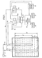
- the tank contents gauge illustrated in Figure 1 is designed for use in locations where it is acceptable to use pressure sensors in the form of hydrostatic probes, such as with petrol in a ventilated tank.
- two pressure sensors A, B each comprise a hollow tube 11 of about 22 mm outer diameter, tube B being longer than tube A.
- the tubes may be copper, stainless steel, a compatible rigid plastics material or metal, according to the required use.
- Each probe 11 has a probe head 12 fitted at the top of the probe outside the tank incorporating a special connector and non-return valve 13 (see Figure 3 for details). This prevents any escape of liquid or gas should one of the air supply tubes be damaged, or in the event of a delivery of liquid when the probe is not pressurised.
- the non-return valves may be fitted inside the probes or within a short distance thereof.
- Each probe has two air lines (14, 15; 14, 16;) connected to the probe head 12 in the form of 6 mm outer diameter tubes. These tubes would normally be nylon, but copper or other materials may be used for certain applications.
- One tube 14 carries air at low pressure from a compressor 17 via a regulator (not shown) and restrictor 18 to the probe 11, whilst the other 15, 16 carries an air pressure rating back to a differential pressure transducer 19. While embodiments of the invention and their operation are described with air as the operating medium, it will be appreciated that other suitable gasses could be used.
- the air for the system may be provided by the separate air compressor 17, or from the on-site air provided it is filtered and reduced to a suitable pressure.
- the lines 15, 16 are connected to respective solenoid valves 21, 22.
- the valve 22 is connected to one side of the pressure transducer 19 and switches the pressure applied to the transducer terminal between line 16 and a line 23 to the solenoid valve 21.
- the valve 21 switches between line 15 and an outlet port 24 which is connected to ambient pressure in the tank. Ambient pressure is also transmitted from the outlet port 24 to the other side of the pressure transducer 19.
- the hydrostatic pressure at the two probes A and B is established, unaffected by any zero error in the transducer.
- the transducer can also be connected to a reference pressure whereby the sensitivity S of the transducer can be determined as described hereafter.
- each tank would have two probes each transmitting air pressure to respective solenoids.
- the solenoids are connected in series with each solenoid switching between a probe line (such as 15) and the next solenoid, except that the first solenoid which would switch between an ambient pressure port and a probe line.
- the last solenoid is connected to the transducer 19.
- the specific gravity of the liquid is also calculated by the system and displayed, or used to calculate the weight of the contents.
- This reading is effected by the sensitivity (S) of the transducer and should the transducer drift, the calculated S.G. will be inaccurate.
- S.G. the sensitivity of the transducer
- the approximate S.G. or weight reading will be sufficient.
- an accurate specific gravity can be determined from the equation where by taking the transducer reading R of a known reference pressure P r transmitted to the transducer.
- the hysteresis factor of the transducer is cancelled out by ensuring that the next pressure measurement is always higher than the previous measurement, and by the method described i.e. ambient-probe A-probe B, this is always achieved. However by reversing the sequence to Probe B-Probe A-ambient, a similar result would be achieved. By using a transducer with a low hysteresis the sequence is not important and the ambient check need only be carried out once for each scan of the vessels.
- the linearity factor can be treated as a variable sensitivity factor S and will therefore cancel out as in equation (3).
- the ratio of the readings becomes higher and non-linearity will have more effect on the accuracy of the readings.
- this problem can be minimised.
- equations (3) and (4) as well as conversion to volume, weight etc. of liquid, can be determined by connecting the pressure transducer 19 to an analogue or analogue and digital processing system 25 having a memory 26 and a display 27. A print out can be provided if required.
- the processing system also switches the solenoids to take the readings automatically via a solenoid control 28.
- a pressure reading with the solenoid valves associated with that tank de-energised is taken to give the offset Z of the transducer which is stored in the memory 26.
- the system 25 compares P a with a pre- programmed figure to check whether the read value is high enough to give a valid depth reading. If so P a is stored.
- equations could have included the offset of the transducer (P replaced by A-Z) and the actual pressure readings at probes A and B could have been stored instead of the corrected pressures.
- the pressure measurements are taken using sealed diaphragm transmitters 29 instead of hydrostatic probes and the pneumatic lines are as illustrated in Figure 2.
- the pressure signals are obtained and used in the same way as has already been described with reference to Figure 1, but may require further processing to compensate for non-linearity within the transmitter.
- a depth of liquid is determined using automatic compensation for specific gravity when the depth of liquid is adequate for a valid reading.
- the method of measurement also compensates for offset and sensitivity of the transducer.
- the way that the apparatus is used means that the effects of hysteresis and non-linearity of the transducer are also as small as possible.
- All tanks are continuously monitored by pressure switches so that in the event of a fill, instant warning is given via an audible alarm, for example when the tank contents reach about 95% of tank capacity. If the apparatus is not being used for data collection, that tank will automatically be selected and the contents displayed. If the apparatus is in use, the display will occur as soon as the use has finished.
- the apparatus can be programmed to scan periodically all the tanks on the system and compare the current alarm position with that of a previous scan. If the level has dropped to or below a predetermined low or extra low level, an audible alarm will sound and the tank or tanks causing the alarm will have their designation and contents displayed, and if a print out is provided, printed.
- the alarm sensors are all housed in a pneumatics cabinet (not shown).
- the cabinet also houses the filters and restrictors 18 for the air supply, as well as the solenoid valves, and an air fail alarm which activates audible and visual warnings should the air from the compressor be interrupted.
- An alarm can also be fitted to give a warning if the S.G. is outside preprogrammed limits, or if more than a pre-programmed amount of contents is removed from a tank at a certain time.
- the processing system 25 can be programmed to use the data collected relating to depth and S.G. in each tank to print out any of the following: volume in tank, weight of contents, delivery capacity, delivery made, volume dispensed since last reading, total of each product dispensed.
- the tank number and date and time of reading would normally be given together with the product in the particular tank if necessary.
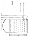
- the two hydrostatic probes A and B are concentrically mounted with the longer tube B inside the shorter tube A.
- a spacer 30 ensures that the probe is displaced from the floor of the tank by a known distance so as to operate effectively out of any sediment that may have settled on the floor of the tank.
- Both the tubes A and B are fitted with diffusers to diffuse the gas passing down them and each tube carries a non-return valve 13 at the top to prevent flow back of the liquid in the tank beyond a predetermined level.
- the probe head 12 connected to the tube B is shown in section to illustrate the non-return valve.
- the diffuser for the probe B can be in the form of a cuboid, the bottom half of which forms the spacer 30.
- the top part of the diffuser which is fluted, is inserted into the bottom of the tube B to form the diffuser 31.
- a single air supply to the inner tube can be used if the two tubes are the same length and the outer tube has an exit in the form of one or more openings at a predetermined position to form the upper sensor and reading P a .
- the distance between the two pressure sensors can be very accurately known.
- a water sensor can be incorporated in the bottom of the probe B.
- a cuboid of composite material is used as spacer and diffuser as described in the preceding paragraph, the lower part of the cuboid being of electrically non-conductive material and the remainder of the cuboid being electrically conductive and connected to a conductivity or capacitance measuring circuit which would indicate the presence of water by means of an audible and/or visual alarm.
Landscapes
- Physics & Mathematics (AREA)
- Fluid Mechanics (AREA)
- General Physics & Mathematics (AREA)
- Measurement Of Levels Of Liquids Or Fluent Solid Materials (AREA)
- Electrical Discharge Machining, Electrochemical Machining, And Combined Machining (AREA)
Claims (5)
Priority Applications (1)
| Application Number | Priority Date | Filing Date | Title |
|---|---|---|---|
| AT81304233T ATE25876T1 (de) | 1980-09-19 | 1981-09-16 | Tankinhalts-messgeraet. |
Applications Claiming Priority (2)
| Application Number | Priority Date | Filing Date | Title |
|---|---|---|---|
| GB8030336 | 1980-09-19 | ||
| GB8030336 | 1980-09-19 |
Publications (2)
| Publication Number | Publication Date |
|---|---|
| EP0048589A1 EP0048589A1 (de) | 1982-03-31 |
| EP0048589B1 true EP0048589B1 (de) | 1987-03-11 |
Family
ID=10516170
Family Applications (1)
| Application Number | Title | Priority Date | Filing Date |
|---|---|---|---|
| EP81304233A Expired EP0048589B1 (de) | 1980-09-19 | 1981-09-16 | Tankinhalts-Messgerät |
Country Status (4)
| Country | Link |
|---|---|
| US (1) | US4669309A (de) |
| EP (1) | EP0048589B1 (de) |
| AT (1) | ATE25876T1 (de) |
| DE (1) | DE3175977D1 (de) |
Cited By (1)
| Publication number | Priority date | Publication date | Assignee | Title |
|---|---|---|---|---|
| DE19620656A1 (de) * | 1995-07-10 | 1997-01-16 | Changmin Co | Ein Pegelmeßverfahren mittels Messungen eines Wassersäulendrucks und eine Vorrichtung zur Durchführung des Verfahrens |
Families Citing this family (56)
| Publication number | Priority date | Publication date | Assignee | Title |
|---|---|---|---|---|
| FR2554230A1 (fr) * | 1983-10-26 | 1985-05-03 | Air Liquide | Procede et appareil pour determiner le poids ou la masse d'un gaz liquefie contenu dans un reservoir |
| FR2564969A1 (fr) * | 1984-05-28 | 1985-11-29 | Suber | Systeme de mesure hydrostatique de niveau de liquide tel que maregraphie capable d'etre etalonne periodiquement par comparaison a des colonnes de liquide de meme nature servant de reference assurant une precision et une fidelite millimetrique |
| EP0214801A1 (de) * | 1985-08-22 | 1987-03-18 | Parmade Instruments C.C. | Verfahren zur Kontrolle des Flüssigkeitsinhaltes eines Behälters, Kontrollvorrichtung zur Verwendung in diesem Verfahren und Anlage mit einer solchen Vorrichtung |
| GB2186317B (en) * | 1986-02-11 | 1990-03-21 | Tankmaster Ltd | Improvements in tank contents measurement |
| AU8336787A (en) * | 1986-11-20 | 1988-06-16 | Nde Technology, Inc. | Volumetric leak detection system for underground storage tanks and the like |
| DE3714956A1 (de) * | 1987-05-06 | 1988-11-17 | Brombach Hansjoerg | Vorrichtung zum ueberwachen von regenueberlaeufen |
| US4885931A (en) * | 1988-03-14 | 1989-12-12 | Horner John A | System for detecting leaks in underground fuel tanks and the like |
| GB8827901D0 (en) * | 1988-11-30 | 1989-01-05 | Shell Int Research | Method & system for measuring vertical density profile of fluid |
| US4928657A (en) * | 1989-03-02 | 1990-05-29 | Walbro Corporation | In-tank fuel reservoir with fuel level sensor |
| DE3914637A1 (de) * | 1989-05-03 | 1990-11-08 | Bosch Gmbh Robert | Fluessigkeitsbehaelter mit hydrostatischem fuellstandsmesser |
| GB9015787D0 (en) * | 1990-07-18 | 1990-09-05 | Thomson Robert M | Hydrostatic liquid level measurement with density correction |
| US5052222A (en) * | 1990-11-05 | 1991-10-01 | Teledyne Exploration | Multiple-unit water depth sensor system |
| GB9102195D0 (en) * | 1991-02-01 | 1991-03-20 | Smiths Industries Plc | Liquid quantity gauging |
| GB2252405B (en) * | 1991-02-01 | 1994-06-22 | Smiths Industries Plc | Liquid quantity gauging |
| US5211678A (en) * | 1991-08-14 | 1993-05-18 | Halliburton Company | Apparatus, method and system for monitoring fluid |
| US5272920A (en) * | 1991-08-14 | 1993-12-28 | Halliburton Company | Apparatus, method and system for monitoring fluid |
| US5163324A (en) * | 1992-02-24 | 1992-11-17 | General Motors Corporation | Bubbler liquid level sensing system |
| CA2098860C (en) * | 1992-07-06 | 1997-03-25 | John Mchardy | Method and apparatus for detecting the position of liquid-liquid interfaces |
| US5289716A (en) * | 1992-08-21 | 1994-03-01 | The United States Of America As Represented By The United States Department Of Energy | Monitoring and analyzing waste glass compositions |
| US5351725A (en) * | 1993-04-01 | 1994-10-04 | Optimum Applied Systems, Inc. | System for monitoring fills of liquid in a tank container and ongoing liquid condition |
| US5309764A (en) * | 1993-05-26 | 1994-05-10 | Itt Corporation | Tank gauging system |
| US5347863A (en) * | 1993-07-02 | 1994-09-20 | Richard Clarence N | Asphalt oil tank monitor |
| US5524682A (en) * | 1994-08-15 | 1996-06-11 | Amonson; Alan | Method and apparatus for filling a tank with a predetermined weight of liquid |
| US5650561A (en) * | 1995-03-13 | 1997-07-22 | Pulse Electronics, Inc. | Diagnostic device for determining the pneumatic health of a bubble-type fuel measuring system |
| DE19514201C2 (de) * | 1995-04-15 | 1997-04-17 | Heinrich Krahn | Vorrichtung zum Messen der Flüssigkeitspegelstände und Flüssigkeitsvolumen in mehreren Behältern |
| US5722289A (en) * | 1996-04-11 | 1998-03-03 | Tridelta Industries, Inc. | Cooking appliance with level detection apparatus and method |
| SE9602986D0 (sv) * | 1996-08-15 | 1996-08-15 | Metall & Bergprodukter Ab | Mätning av medievolym |
| SE9803048D0 (sv) * | 1998-09-09 | 1998-09-09 | Siemens Elema Ab | Dispenser unit for non-gaseous flowable material |
| US6234019B1 (en) * | 1999-02-19 | 2001-05-22 | Smar Research Corporation | System and method for determining a density of a fluid |
| US6418792B1 (en) * | 1999-09-24 | 2002-07-16 | Stephen Edward Spychalski | Pressure compensated transducer |
| NO322125B1 (no) * | 2001-02-07 | 2006-08-14 | 4Tech Asa | Nivamaler for maling av vaeskemengde i tank |
| CA2340139A1 (fr) * | 2001-03-08 | 2002-09-08 | Hydro-Quebec | Dispositif d'autoverification d'un appareil de mesure de niveau bulle a bulle |
| US6601449B1 (en) * | 2001-05-24 | 2003-08-05 | Derrick A. Jones | Self-regulating bubble tube assembly |
| AT411711B (de) * | 2002-04-30 | 2004-04-26 | Hoffmann La Roche | Verfahren zur bestimmung des aktuellen füllstandes einer flüssigkeit in einem behälter |
| US6938635B2 (en) * | 2002-07-26 | 2005-09-06 | Exxonmobil Research And Engineering Company | Level switch with verification capability |
| US6805070B2 (en) * | 2002-10-09 | 2004-10-19 | Honda Giken Kogyo Kabushiki Kaisha | Fluid container with level indicator, and fluid level indicator assembly for a fluid container |
| US7000468B2 (en) | 2003-04-04 | 2006-02-21 | Bunn-O-Matic Corporation | Electronic level gauge |
| US6928862B1 (en) * | 2003-12-04 | 2005-08-16 | Bryce V. Robbins | Method of monitoring dual-phase liquid and interface levels |
| RU2280844C1 (ru) * | 2004-12-27 | 2006-07-27 | Владимир Алексеевич Копяк | Способ контроля уровня жидкого металла |
| EP1883792A4 (de) * | 2005-05-11 | 2009-07-08 | Innovative Solutions & Support | System und verfahren zur überwachung der flugzeugtreibstoffkapazität auf druckbasis |
| DE102005059943A1 (de) * | 2005-12-13 | 2007-03-22 | Esyoll Gmbh | Explosionsgeschützte Messanordnung zur Füllstandsmessung nach dem Einperl-Verfahren |
| GB2433783A (en) * | 2005-12-20 | 2007-07-04 | Bcb Coated Stone Ltd | Air column type liquid level sensor |
| NZ569982A (en) * | 2006-02-15 | 2011-06-30 | Samaran Internat Pty Ltd | Septic tanks with pressure sensor |
| US7895890B2 (en) * | 2007-07-03 | 2011-03-01 | Van Ee William J | Liquid depth sensing and identification system |
| AU2008217000B2 (en) * | 2007-09-21 | 2012-02-09 | Multitrode Pty Ltd | A pumping installation controller |
| CN102003988A (zh) * | 2010-10-27 | 2011-04-06 | 江苏科技大学 | 间歇吹泡式液位计 |
| CN101988844A (zh) * | 2010-11-16 | 2011-03-23 | 江苏科技大学 | 一种双管间歇吹泡式液位计 |
| WO2013162453A1 (en) * | 2012-04-23 | 2013-10-31 | Kockum Sonics Ab | A liquid level measurement apparatus, arrangement and method using bubble measurement |
| JP6426371B2 (ja) * | 2014-05-16 | 2018-11-21 | 株式会社東芝 | 投込式水位計の校正システム、その校正方法、および校正機能付き投込式水位計 |
| JP6486758B2 (ja) * | 2015-04-28 | 2019-03-20 | 株式会社東芝 | 投込式水位計の調節システム、その調節方法、その調節プログラムおよび調節機能付き投込式水位計 |
| JP6483515B2 (ja) * | 2015-04-28 | 2019-03-13 | 株式会社東芝 | 投込式水位計の補助システム、その補助方法、その補助プログラムおよび補助機能付き投込式水位計 |
| CA2989336C (en) * | 2015-06-18 | 2022-05-10 | Fts Forest Technology Systems Ltd. | Sensor for remote measurement of fluid depth in environmental monitoring |
| US11933654B2 (en) * | 2016-06-14 | 2024-03-19 | Watgrid, S.A. | Level and/or density sensor device for liquid vessels |
| US9958312B1 (en) | 2017-04-18 | 2018-05-01 | Texas Lfp, Llc | Liquid level gauge for pressurized tanks |
| DE102018105729A1 (de) * | 2018-03-13 | 2019-09-19 | Thomas Petersen | Verfahren zum Befüllen eines aus einer Mehrzahl von Behältern bestehenden Batterietanks und System zur Überwachung des Befüllvorgangs eines Batterietanks |
| US11885728B2 (en) * | 2020-12-23 | 2024-01-30 | Battelle Energy Alliance, Llc | Mass measurement systems and related methods for measuring mass of solids within a liquid |
Family Cites Families (14)
| Publication number | Priority date | Publication date | Assignee | Title |
|---|---|---|---|---|
| DE156575C (de) * | ||||
| US1681504A (en) * | 1925-07-28 | 1928-08-21 | Smithe Machine Co Inc F L | Liquid-level gauge |
| US2041859A (en) * | 1934-09-14 | 1936-05-26 | Du Pont | Liquid level indicator |
| US2613535A (en) * | 1949-12-08 | 1952-10-14 | Paul L Born | Liquid level gauge |
| US2755669A (en) * | 1952-11-29 | 1956-07-24 | Honeywell Regulator Co | Bubble tube |
| US3182502A (en) * | 1962-01-24 | 1965-05-11 | Sun Oil Co | Tank gauge apparatus |
| US3373609A (en) * | 1964-07-22 | 1968-03-19 | Sundby Per Rohrt | System for measuring the height of the liquid level in tanks |
| FR2038714A5 (de) * | 1969-03-27 | 1971-01-08 | Cermat | |
| GB1449164A (en) * | 1973-06-08 | 1976-09-15 | Westinghouse Brake & Signal | Pnematic level sensing |
| FR2250985B1 (de) * | 1973-11-08 | 1977-08-05 | Cermat | |
| DE2510191C2 (de) * | 1975-03-08 | 1977-04-28 | Bergwerksverband Gmbh | Pneumatische fuellstandsmessung |
| SE407980B (sv) * | 1977-02-17 | 1979-04-30 | Egnell Axel | Anordning for indikering av en vetskas niva och densitet i en tank |
| US4422327A (en) * | 1981-03-18 | 1983-12-27 | Ingenjorsfirman Installationsjanst AB | Liquid level indicator apparatus |
| US4393705A (en) * | 1981-07-27 | 1983-07-19 | Micro-Plate, Inc. | Specific gravity level gauge and method |
-
1981
- 1981-09-16 AT AT81304233T patent/ATE25876T1/de active
- 1981-09-16 EP EP81304233A patent/EP0048589B1/de not_active Expired
- 1981-09-16 DE DE8181304233T patent/DE3175977D1/de not_active Expired
-
1984
- 1984-01-30 US US06/575,268 patent/US4669309A/en not_active Expired - Fee Related
Cited By (2)
| Publication number | Priority date | Publication date | Assignee | Title |
|---|---|---|---|---|
| DE19620656A1 (de) * | 1995-07-10 | 1997-01-16 | Changmin Co | Ein Pegelmeßverfahren mittels Messungen eines Wassersäulendrucks und eine Vorrichtung zur Durchführung des Verfahrens |
| DE19620656C2 (de) * | 1995-07-10 | 2000-02-03 | Chang Min Tech Co | Pegelmeßverfahren |
Also Published As
| Publication number | Publication date |
|---|---|
| EP0048589A1 (de) | 1982-03-31 |
| ATE25876T1 (de) | 1987-03-15 |
| US4669309A (en) | 1987-06-02 |
| DE3175977D1 (en) | 1987-04-16 |
Similar Documents
| Publication | Publication Date | Title |
|---|---|---|
| US4669309A (en) | Tank contents gauge | |
| US4852054A (en) | Volumetric leak detection system for underground storage tanks and the like | |
| US4630478A (en) | Liquid volume sensor system | |
| US4006635A (en) | Liquid level measuring process and indicator | |
| KR100228410B1 (ko) | 스트레인 게이지식 로드셀을 이용한 액체 액위/유량 측정 시스템 및 그 측정방법 | |
| US5243860A (en) | Liquid level measurement | |
| US6234019B1 (en) | System and method for determining a density of a fluid | |
| US11788872B2 (en) | Method and system for determination of liquid volumes | |
| US20090272188A1 (en) | Binary Liquid Analyzer For Storage Tank | |
| WO1991018266A1 (en) | Fluid pressure operated volume measurement with level calibration means | |
| US4819483A (en) | Level indicator control system for use with capacitance probes in tanks containing substances | |
| US4649739A (en) | Method of detecting leaks in liquid storage tanks | |
| WO1988004031A1 (en) | Volumetric leak detection system for underground storage tanks and the like | |
| US4747062A (en) | Method and apparatus for detecting the level of a liquid in a tank | |
| US3620085A (en) | Apparatus for measuring the level of liquid in a reservoir | |
| US4885931A (en) | System for detecting leaks in underground fuel tanks and the like | |
| WO1994007122A1 (en) | Density measurement | |
| US5493903A (en) | Method of determining the volume of a substance having a density, in vertical storage tanks | |
| WO1994002820A1 (en) | Water sensor that detects tank or vessel leakage | |
| WO2017115949A1 (ko) | 자기왜곡방식의 거리측정을 이용한 테이퍼관형 면적식 유량계 | |
| US3964037A (en) | Fuel tank alarm systems | |
| RU2296958C2 (ru) | Способ градуировки газовых расходомеров и устройство его реализации | |
| US3579218A (en) | Attitude error detection fluid gauging system without correction | |
| US4091669A (en) | Pressure responsive apparatus | |
| AU2001290187B2 (en) | Method and apparatus for determining the volume of liquid in a reservoir |
Legal Events
| Date | Code | Title | Description |
|---|---|---|---|
| PUAI | Public reference made under article 153(3) epc to a published international application that has entered the european phase |
Free format text: ORIGINAL CODE: 0009012 |
|
| AK | Designated contracting states |
Designated state(s): AT BE CH DE FR GB IT LU NL SE |
|
| 17P | Request for examination filed |
Effective date: 19821001 |
|
| RAP1 | Party data changed (applicant data changed or rights of an application transferred) |
Owner name: TANKMASTER LIMITED |
|
| GRAA | (expected) grant |
Free format text: ORIGINAL CODE: 0009210 |
|
| AK | Designated contracting states |
Kind code of ref document: B1 Designated state(s): AT BE CH DE FR GB IT LI LU NL SE |
|
| REF | Corresponds to: |
Ref document number: 25876 Country of ref document: AT Date of ref document: 19870315 Kind code of ref document: T |
|
| REF | Corresponds to: |
Ref document number: 3175977 Country of ref document: DE Date of ref document: 19870416 |
|
| ET | Fr: translation filed | ||
| ITF | It: translation for a ep patent filed | ||
| PG25 | Lapsed in a contracting state [announced via postgrant information from national office to epo] |
Ref country code: LU Free format text: LAPSE BECAUSE OF NON-PAYMENT OF DUE FEES Effective date: 19870930 |
|
| PLBE | No opposition filed within time limit |
Free format text: ORIGINAL CODE: 0009261 |
|
| STAA | Information on the status of an ep patent application or granted ep patent |
Free format text: STATUS: NO OPPOSITION FILED WITHIN TIME LIMIT |
|
| 26N | No opposition filed | ||
| PGFP | Annual fee paid to national office [announced via postgrant information from national office to epo] |
Ref country code: LU Payment date: 19900821 Year of fee payment: 10 |
|
| PGFP | Annual fee paid to national office [announced via postgrant information from national office to epo] |
Ref country code: BE Payment date: 19900831 Year of fee payment: 10 |
|
| PGFP | Annual fee paid to national office [announced via postgrant information from national office to epo] |
Ref country code: SE Payment date: 19900917 Year of fee payment: 10 |
|
| PGFP | Annual fee paid to national office [announced via postgrant information from national office to epo] |
Ref country code: FR Payment date: 19900926 Year of fee payment: 10 |
|
| PGFP | Annual fee paid to national office [announced via postgrant information from national office to epo] |
Ref country code: AT Payment date: 19900928 Year of fee payment: 10 |
|
| ITTA | It: last paid annual fee | ||
| PGFP | Annual fee paid to national office [announced via postgrant information from national office to epo] |
Ref country code: CH Payment date: 19901213 Year of fee payment: 10 |
|
| PG25 | Lapsed in a contracting state [announced via postgrant information from national office to epo] |
Ref country code: AT Effective date: 19910916 |
|
| PG25 | Lapsed in a contracting state [announced via postgrant information from national office to epo] |
Ref country code: SE Effective date: 19910917 |
|
| PG25 | Lapsed in a contracting state [announced via postgrant information from national office to epo] |
Ref country code: LI Effective date: 19910930 Ref country code: CH Effective date: 19910930 Ref country code: BE Effective date: 19910930 |
|
| BERE | Be: lapsed |
Owner name: TANKMASTER LTD Effective date: 19910930 |
|
| PG25 | Lapsed in a contracting state [announced via postgrant information from national office to epo] |
Ref country code: FR Effective date: 19920529 |
|
| REG | Reference to a national code |
Ref country code: CH Ref legal event code: PL |
|
| REG | Reference to a national code |
Ref country code: FR Ref legal event code: ST |
|
| PGFP | Annual fee paid to national office [announced via postgrant information from national office to epo] |
Ref country code: NL Payment date: 19940930 Year of fee payment: 14 |
|
| PGFP | Annual fee paid to national office [announced via postgrant information from national office to epo] |
Ref country code: DE Payment date: 19941114 Year of fee payment: 14 |
|
| EUG | Se: european patent has lapsed |
Ref document number: 81304233.0 Effective date: 19920408 |
|
| PG25 | Lapsed in a contracting state [announced via postgrant information from national office to epo] |
Ref country code: NL Effective date: 19960401 |
|
| NLV4 | Nl: lapsed or anulled due to non-payment of the annual fee |
Effective date: 19960401 |
|
| PG25 | Lapsed in a contracting state [announced via postgrant information from national office to epo] |
Ref country code: DE Effective date: 19960702 |
|
| PGFP | Annual fee paid to national office [announced via postgrant information from national office to epo] |
Ref country code: GB Payment date: 20000912 Year of fee payment: 20 |
|
| PG25 | Lapsed in a contracting state [announced via postgrant information from national office to epo] |
Ref country code: GB Free format text: LAPSE BECAUSE OF EXPIRATION OF PROTECTION Effective date: 20010915 |
|
| REG | Reference to a national code |
Ref country code: GB Ref legal event code: PE20 Effective date: 20010915 |