EP0048672A1 - Atomkernreaktor mit Wärmetauschern in integrierter Bauweise - Google Patents
Atomkernreaktor mit Wärmetauschern in integrierter Bauweise Download PDFInfo
- Publication number
- EP0048672A1 EP0048672A1 EP81401454A EP81401454A EP0048672A1 EP 0048672 A1 EP0048672 A1 EP 0048672A1 EP 81401454 A EP81401454 A EP 81401454A EP 81401454 A EP81401454 A EP 81401454A EP 0048672 A1 EP0048672 A1 EP 0048672A1
- Authority
- EP
- European Patent Office
- Prior art keywords
- reactor
- exchangers
- tank
- sodium
- heat exchangers
- Prior art date
- Legal status (The legal status is an assumption and is not a legal conclusion. Google has not performed a legal analysis and makes no representation as to the accuracy of the status listed.)
- Granted
Links
- DGAQECJNVWCQMB-PUAWFVPOSA-M Ilexoside XXIX Chemical group C[C@@H]1CC[C@@]2(CC[C@@]3(C(=CC[C@H]4[C@]3(CC[C@@H]5[C@@]4(CC[C@@H](C5(C)C)OS(=O)(=O)[O-])C)C)[C@@H]2[C@]1(C)O)C)C(=O)O[C@H]6[C@@H]([C@H]([C@@H]([C@H](O6)CO)O)O)O.[Na+] DGAQECJNVWCQMB-PUAWFVPOSA-M 0.000 claims abstract description 56
- 229910052708 sodium Inorganic materials 0.000 claims abstract description 56
- 239000011734 sodium Substances 0.000 claims abstract description 56
- 239000007788 liquid Substances 0.000 claims abstract description 32
- 230000000284 resting effect Effects 0.000 claims abstract description 7
- 230000000712 assembly Effects 0.000 claims description 11
- 238000000429 assembly Methods 0.000 claims description 11
- 239000000446 fuel Substances 0.000 claims description 10
- 239000012530 fluid Substances 0.000 claims description 5
- 238000010438 heat treatment Methods 0.000 claims description 5
- 238000004519 manufacturing process Methods 0.000 claims description 3
- 230000002093 peripheral effect Effects 0.000 description 7
- 238000006073 displacement reaction Methods 0.000 description 2
- 239000003651 drinking water Substances 0.000 description 2
- 235000020188 drinking water Nutrition 0.000 description 2
- 238000012423 maintenance Methods 0.000 description 2
- 230000005540 biological transmission Effects 0.000 description 1
- 238000004891 communication Methods 0.000 description 1
- 238000010276 construction Methods 0.000 description 1
- 238000005259 measurement Methods 0.000 description 1
- 230000007246 mechanism Effects 0.000 description 1
- 238000007789 sealing Methods 0.000 description 1
- 125000006850 spacer group Chemical group 0.000 description 1
- 238000009834 vaporization Methods 0.000 description 1
- 230000008016 vaporization Effects 0.000 description 1
- XLYOFNOQVPJJNP-UHFFFAOYSA-N water Chemical compound O XLYOFNOQVPJJNP-UHFFFAOYSA-N 0.000 description 1
- 238000003466 welding Methods 0.000 description 1
Images

Classifications
-
- G—PHYSICS
- G21—NUCLEAR PHYSICS; NUCLEAR ENGINEERING
- G21C—NUCLEAR REACTORS
- G21C1/00—Reactor types
- G21C1/02—Fast fission reactors, i.e. reactors not using a moderator ; Metal cooled reactors; Fast breeders
- G21C1/03—Fast fission reactors, i.e. reactors not using a moderator ; Metal cooled reactors; Fast breeders cooled by a coolant not essentially pressurised, e.g. pool-type reactors
-
- Y—GENERAL TAGGING OF NEW TECHNOLOGICAL DEVELOPMENTS; GENERAL TAGGING OF CROSS-SECTIONAL TECHNOLOGIES SPANNING OVER SEVERAL SECTIONS OF THE IPC; TECHNICAL SUBJECTS COVERED BY FORMER USPC CROSS-REFERENCE ART COLLECTIONS [XRACs] AND DIGESTS
- Y02—TECHNOLOGIES OR APPLICATIONS FOR MITIGATION OR ADAPTATION AGAINST CLIMATE CHANGE
- Y02E—REDUCTION OF GREENHOUSE GAS [GHG] EMISSIONS, RELATED TO ENERGY GENERATION, TRANSMISSION OR DISTRIBUTION
- Y02E30/00—Energy generation of nuclear origin
- Y02E30/30—Nuclear fission reactors
Definitions
- the invention relates to a nuclear reactor with integrated heat exchangers, cooled with liquid sodium.
- Fast neutron nuclear reactors cooled by liquid sodium have a core consisting of fuel assemblies resting on a horizontal support placed inside a tank containing liquid sodium constituting the primary fluid of the reactor in which all of the fuel assemblies. Liquid sodium coming into contact with the assemblies or primary sodium is not used directly for the transmission of heat from the reactor core to the steam generator producing the steam supplying the turbine.
- the primary sodium which is circulated inside the tank by pumps, allows the heating of secondary liquid sodium inside intermediate heat exchangers.
- the pumps for circulating the primary sodium and the intermediate exchangers are arranged inside the reactor vessel and are therefore immersed, just like the heart of the latter, in the primary sodium filling the vessel.
- the secondary liquid sodium circulates in a closed circuit between the intermediate exchangers and the steam generators where the heat transported by this secondary liquid sodium allows the vaporization of drinking water and the production of the steam used by the turbine.
- the reactor vessel is closed at its upper part by a large horizontal slab in which are made openings for the passage of the components of the reactor and of the measurement devices associated with it which are generally of elongated shape and arranged vertically.
- the lower part of these components or measuring devices penetrates inside the tank through openings provided in the slab, while the upper part of the component or measuring device rests on the slab outside the tank. , which ensures the maintenance of this component or measuring device.
- a sealing device disposed between the component and the slab allows the component to seal the openings in the slab.
- the primary pumps and the intermediate heat exchangers are arranged in this way at the level of openings provided in the slab.
- a large opening is provided in the central part of the slab vertically above the reactor core. This opening is intended to receive an assembly allowing the control of the reactor by displacement of neutron absorbing bars in the core and a device for handling the fuel assemblies to carry out the operations of loading and unloading of the core of the reactor.
- control assembly and the handling device are carried by a horizontal platform movable in rotation about a vertical axis, called a large rotating plug, closing the opening in the reactor slab.
- control assembly and the assembly handling device are mounted on a circular platform called a small rotating plug, of smaller dimensions than the large rotating plug and rotatably mounted on the large rotating plug around a vertical axis different from the axis of rotation thereof.
- the large rotating plug has a diameter greater than the diameter of the cylinder with a vertical axis encompassing the entire core.
- This arrangement of the intermediate heat exchangers which number 8 in the case of the fast neutron nuclear reactors with a power of 1200 MW which are currently being constructed, requires the provision of a large diameter slab and a tank to allow the arrangement of weight components. important which are supported on the slab at the peripheral part thereof.
- the reactor vessel is therefore of a diameter much greater than the diameter of the core, generally of the order of three times the diameter of the core.
- the tank containing the liquid sodium in which the reactor core and the main components of it are surrounded is also surrounded by a safety tank which further increases the size of the tank assembly. To reduce the cost of building the nuclear reactor and to reduce the amount of primary liquid sodium filling this tank, it is therefore desirable to reduce the diameter of the tank.
- the object of the invention is therefore to propose a nuclear reactor with integrated heat exchangers comprising, in a tank containing liquid sodium constituting the primary fluid in which the reactor core is immersed formed by fuel assemblies resting on a horizontal support. support on the lower part of the tank, at least two intermediate heat exchangers allowing the heating of secondary liquid sodium by the liquid sodium contained in the tank, or primary sodium, of generally cylindrical and elongated shape and each connected to a circuit of transport of the secondary sodium between the intermediate exchanger and a steam generator for the production of water vapor thanks to the heat transported by the secondary sodium, the reactor vessel being closed by a horizontal slab in which are formed openings of which the 'one, large and arranged above the heart, is equipped with a platform rotatably mounted around a vertical axis, called a large rotating plug, carrying the control assembly of the nuclear reactor and a device for handling the fuel assemblies, the intermediate exchangers entirely contained in the tank being connected to the secondary sodium circuit by pipes passing through the reactor slab, this nuclear reactor must include a tank of reduced diameter,
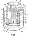
- Figure 1 shows a vertical sectional view of the nuclear reactor vessel.
- FIG. 2 represents a plan view of the tank represented in FIG. 1, the lower part of FIG. 2 being constituted by a half-view of the top of the tank and the upper part of FIG. 2 by a half-view in section of the tank at level AA marked in Figure 1.
- FIG. 3 represents a perspective view of an intermediate heat exchanger disposed inside the vessel of the nuclear reactor.
- FIG. 1 we see the main tank 1 of the reactor filled with liquid sodium up to level 2a in the peripheral part and 2b in the central part, inside the cylinder constituting the internal tank.
- a structure 3 rests on the lower part of the tank and carries a box spring 4 constituting the support of the reactor core.
- the reactor core is made up of fuel assemblies 6 and surrounded by vertical bars 7 constituting the lateral neutron protection of the reactor, the assembly resting on the bed base 4.
- the tank 1 is closed by a very thick slab 8 comprising at its central part an opening 10 of large dimension.
- a platform 15 constituting the large rotating plug.
- the large rotating plug has a circular section, as shown in the lower part of FIG. 2 and has a frustoconical shape with axis 12.
- the small rotating plug 16 carries a device for handling the fuel assemblies 20 and the core cover plug 21 of the reactor carrying mechanisms such as 22 and 23 allowing the displacement of the reactor control rods.
- a line 32 is connected to the lower part of the pump, through which the liquid sodium entering the pump body is discharged through openings 31.
- Line 32 opens into the structure of the bed base 4 supporting the core 5 of the reactor.
- Circulation is thus imposed on the liquid sodium constituting the primary fluid recovering the calories released by the core 5 of the reactor.
- the liquid sodium discharged by the pump 25 at the base of the core 5 of the reactor comes into contact with the fuel assemblies 6 and passes vertically, from bottom to top, the core 5 while heating.
- the hot primary liquid sodium opening at the upper part of the heart then enters the intermediate exchangers to heat the secondary sodium.
- FIG. 1 an intermediate exchanger 35 can be seen, the body of which consists of a portion of cylinder, the cross section of which is visible in FIG. 2.
- This exchanger 35 has also been shown in perspective in FIG. 3. It has an external envelope having two cylindrical faces of the same axis and two planar faces passing through this axis.
- the intermediate heat exchangers such as the exchanger 35 rest by their lower parts on the bed base 4 supporting the core and are arranged at the periphery of the reactor core in a space in the form of a cylinder portion surrounding the reactor core and the control assembly carried by the core cover plug 21.
- the section of these intermediate exchangers in the form of a crown portion therefore adapts perfectly the most efficient possible filling of this space in the form of a cylinder portion.
- Each exchanger has two cylindrical surfaces with the same axis 12, one directed towards the core of the reactor and the other towards the internal wall of the tank 1 and two flat surfaces passing through the axis 12.
- the exchanger 35 has at its upper part an opening 36 directed towards the reactor core allowing the entry of the heated primary liquid sodium coming from the core.
- the exchanger 35 also has an opening 37 at its lower part and directed towards the internal wall of the tank for the exit of the primary sodium.
- the circulation of the primary liquid sodium in the reactor has been represented by arrows.
- the opening 37 can be closed by a shutter 38.
- a tubular bundle 40 Inside the body of the exchanger 35 is disposed a tubular bundle 40 whose small diameter tubes are held by spacer plates 41, these tubes constituting the bundle being fixed on end plates 42 and 43.
- a vertical pipe 46 is likewise connected to the lower part of the body of the heat exchanger below the end plate 43, that is to say in an area where all of the bundle tubes open out.
- Lines 44 and 46 are connected to the secondary liquid sodium circuit used to heat and vaporize the drinking water inside the steam generator.
- the secondary sodium during its circulation in the tubes of the bundle 40 is heated by the primary liquid sodium which flows in contact with the external wall of the tubes of the bundle 40.
- the pipe 44 is connected to a pipe 50 passing through the slab 8 of the reactor in its peripheral part outside the opening 10 inside which the large rotating plug 15 is disposed.
- the pipe 46 crosses the slab 8 in its peripheral zone.
- the intermediate exchangers such as 35 are therefore disposed entirely inside the tank 1 below the level of liquid sodium 2, the pipes of the liquid sodium circuit passing through the slab 8.
- the large rotating plug 15 is pierced with an opening 53 over its entire thickness, this opening 53 as it can be seen in FIG. 2, having the shape of the cross section of the intermediate exchangers and a slightly larger dimension. to the dimension of this cross section.
- the opening 53 is located on the other hand at a distance from the axis 12 of the large rotating plug making it possible to place this opening 53. above each of the intermediate exchangers 35 a ; 35, 35 This 35 successively so as to be able to access these exchangers.
- the opening 53 after dismantling the pipes such as 50 making it possible to join the pipes 44-46 to the secondary sodium circuit, it is possible to remove the exchanger from the reactor vessel by introducing through the opening 53 a means lifting.
- One of the main advantages of the invention is to allow a reduction in the diameter of the tank since the peripheral part of the slab outside the large rotating plug only carries the primary pumps as an element of significant weight and that we can therefore reduce the size of the slab. Indeed, when the intermediate exchangers, for example 8 in the case of a nuclear reactor with a power of 1200 MW, are arranged on the periphery of the tank between the primary pumps, it is necessary to provide sufficient spacing of these various components of significant weight for questions of resistance of the slab and for questions of space inside the tank.
- a reduction in the diameter of the tank by a few meters is possible for a tank usually with a diameter close to 20 m.
- a reduction in this order of the size of the tank allows savings to be made during the construction of the tank, the slab and of the reactor building.
- the invention is not limited to the embodiment which has just been described, on the contrary it includes all the variants thereof.
- This is how intermediate exchangers have been described having sections in cylinder portions making it possible to achieve great compactness in the arrangement of the elements inside the tank, but it is also possible to use more conventional intermediate exchangers of cylindrical shape with circular section.
- the pipes connecting the intermediate exchangers to the secondary sodium circuit can be fixed to these exchangers at their secondary sodium inlet or outlet pipe, by welding or by a removable mechanical connection such as a connection comprising screwed elements.
- the invention also applies to any nuclear reactor cooled by liquid sodium comprising intermediate exchangers arranged in the reactor vessel, regardless of the number of these exchangers and regardless of the number of primary fluid circulation pumps inside the tank.
Landscapes
- Physics & Mathematics (AREA)
- Engineering & Computer Science (AREA)
- Plasma & Fusion (AREA)
- General Engineering & Computer Science (AREA)
- High Energy & Nuclear Physics (AREA)
- Heat-Exchange Devices With Radiators And Conduit Assemblies (AREA)
Applications Claiming Priority (2)
| Application Number | Priority Date | Filing Date | Title |
|---|---|---|---|
| FR8020180 | 1980-09-19 | ||
| FR8020180A FR2490862B1 (fr) | 1980-09-19 | 1980-09-19 | Reacteur nucleaire a echangeurs de chaleur integres |
Publications (2)
| Publication Number | Publication Date |
|---|---|
| EP0048672A1 true EP0048672A1 (de) | 1982-03-31 |
| EP0048672B1 EP0048672B1 (de) | 1984-07-18 |
Family
ID=9246087
Family Applications (1)
| Application Number | Title | Priority Date | Filing Date |
|---|---|---|---|
| EP81401454A Expired EP0048672B1 (de) | 1980-09-19 | 1981-09-18 | Atomkernreaktor mit Wärmetauschern in integrierter Bauweise |
Country Status (5)
| Country | Link |
|---|---|
| US (1) | US4397811A (de) |
| EP (1) | EP0048672B1 (de) |
| JP (1) | JPS5784391A (de) |
| DE (1) | DE3164892D1 (de) |
| FR (1) | FR2490862B1 (de) |
Cited By (3)
| Publication number | Priority date | Publication date | Assignee | Title |
|---|---|---|---|---|
| EP0141158A1 (de) * | 1983-09-08 | 1985-05-15 | Hitachi, Ltd. | Schneller Brutreaktor mit doppeltem Tank |
| EP0143916A1 (de) * | 1983-09-08 | 1985-06-12 | Hitachi, Ltd. | Schnellbrüter-Kernreaktor vom Tank-Typ |
| CN111951985A (zh) * | 2020-07-15 | 2020-11-17 | 四川大学 | 一种模块化空间核反应堆发电单元 |
Families Citing this family (2)
| Publication number | Priority date | Publication date | Assignee | Title |
|---|---|---|---|---|
| JPS59104291A (ja) * | 1982-12-06 | 1984-06-16 | Kobe Steel Ltd | ガスシ−ルドア−ク溶接用フラツクス入りワイヤ |
| JPS6051496U (ja) * | 1983-09-19 | 1985-04-11 | 三菱重工業株式会社 | 原子炉 |
Citations (6)
| Publication number | Priority date | Publication date | Assignee | Title |
|---|---|---|---|---|
| GB985463A (en) * | 1962-10-17 | 1965-03-10 | Atomic Energy Authority Uk | Improvements relating to nuclear reactors |
| FR2099666A1 (de) * | 1970-07-29 | 1972-03-17 | British Nuclear Design Constr | |
| DE2346868A1 (de) * | 1973-09-18 | 1975-03-20 | Interatom | Kernreaktor mit schildwand zwischen kuehlmittelsammelraum und druckbehaelterwandung |
| FR2316704A1 (fr) * | 1975-06-20 | 1977-01-28 | Atomic Energy Authority Uk | Reacteur nucleaire refroidi par un metal liquide |
| DE2812056A1 (de) * | 1977-03-21 | 1978-10-12 | Commissariat Energie Atomique | Waermeaustauscher |
| FR2404897A2 (fr) * | 1970-08-05 | 1979-04-27 | Electricite De France | Reacteur nucleaire a echangeurs integres |
Family Cites Families (2)
| Publication number | Priority date | Publication date | Assignee | Title |
|---|---|---|---|---|
| FR89891E (fr) * | 1966-04-07 | 1967-09-01 | Babcock & Wilcox France | Perfectionnements aux installations génératrices d'énergie |
| FR2419565A1 (fr) * | 1978-03-07 | 1979-10-05 | Commissariat Energie Atomique | Echangeur d'ultime secours, notamment pour reacteur nucleaire a neutrons rapides |
-
1980
- 1980-09-19 FR FR8020180A patent/FR2490862B1/fr not_active Expired
-
1981
- 1981-08-10 US US06/291,678 patent/US4397811A/en not_active Expired - Fee Related
- 1981-09-18 EP EP81401454A patent/EP0048672B1/de not_active Expired
- 1981-09-18 DE DE8181401454T patent/DE3164892D1/de not_active Expired
- 1981-09-18 JP JP56147727A patent/JPS5784391A/ja active Pending
Patent Citations (6)
| Publication number | Priority date | Publication date | Assignee | Title |
|---|---|---|---|---|
| GB985463A (en) * | 1962-10-17 | 1965-03-10 | Atomic Energy Authority Uk | Improvements relating to nuclear reactors |
| FR2099666A1 (de) * | 1970-07-29 | 1972-03-17 | British Nuclear Design Constr | |
| FR2404897A2 (fr) * | 1970-08-05 | 1979-04-27 | Electricite De France | Reacteur nucleaire a echangeurs integres |
| DE2346868A1 (de) * | 1973-09-18 | 1975-03-20 | Interatom | Kernreaktor mit schildwand zwischen kuehlmittelsammelraum und druckbehaelterwandung |
| FR2316704A1 (fr) * | 1975-06-20 | 1977-01-28 | Atomic Energy Authority Uk | Reacteur nucleaire refroidi par un metal liquide |
| DE2812056A1 (de) * | 1977-03-21 | 1978-10-12 | Commissariat Energie Atomique | Waermeaustauscher |
Cited By (5)
| Publication number | Priority date | Publication date | Assignee | Title |
|---|---|---|---|---|
| EP0141158A1 (de) * | 1983-09-08 | 1985-05-15 | Hitachi, Ltd. | Schneller Brutreaktor mit doppeltem Tank |
| EP0143916A1 (de) * | 1983-09-08 | 1985-06-12 | Hitachi, Ltd. | Schnellbrüter-Kernreaktor vom Tank-Typ |
| US4645633A (en) * | 1983-09-08 | 1987-02-24 | Central Research Institute Of Electric Power Industry, Toshiba Corporation | Double tank type fast breeder reactor |
| CN111951985A (zh) * | 2020-07-15 | 2020-11-17 | 四川大学 | 一种模块化空间核反应堆发电单元 |
| CN111951985B (zh) * | 2020-07-15 | 2022-10-18 | 四川大学 | 一种模块化空间核反应堆发电单元 |
Also Published As
| Publication number | Publication date |
|---|---|
| EP0048672B1 (de) | 1984-07-18 |
| JPS5784391A (en) | 1982-05-26 |
| DE3164892D1 (en) | 1984-08-23 |
| US4397811A (en) | 1983-08-09 |
| FR2490862B1 (fr) | 1985-08-30 |
| FR2490862A1 (fr) | 1982-03-26 |
Similar Documents
| Publication | Publication Date | Title |
|---|---|---|
| FR2481506A1 (fr) | Dispositif de cloisonnement du coeur d'un reacteur nucleaire par des elements amovibles | |
| EP0246969B1 (de) | Kleiner Druckwasserkernreaktor mit Naturumlauf | |
| EP0048672B1 (de) | Atomkernreaktor mit Wärmetauschern in integrierter Bauweise | |
| EP0153225B1 (de) | Wärmetauscher mit einem Notkühlsystem und schneller Kernreaktor mit einem derartigen Wärmetauscher | |
| EP0018262B1 (de) | Schneller Kernreaktor mit einem zylindrischen Innenbehälter | |
| EP0067103B1 (de) | Schneller Brutreaktor | |
| EP0258131B1 (de) | Notkühleinrichtung für schnellen Neutronenreaktor | |
| EP0173602A1 (de) | Notwärmetauscher zur Kühlung des Primärmittels eines Kernreaktors und Verfahren zu dessen Zusammenbau | |
| FR2497388A1 (fr) | Reacteur nucleaire refroidi par un metal liquide et comprenant une cuve posee a fond froid | |
| EP0064920B1 (de) | Vorrichtung zur Dampferzeugung und zur Ableitung von Wärme in einem schnellen Brüter | |
| FR2484125A1 (fr) | Dispositif de cloisonnement du coeur d'un reacteur nucleaire | |
| EP0117191A1 (de) | Dampferzeuger für einen flüssigmetallgekühlten nuklearen Reaktor | |
| EP0091872B1 (de) | Kollektor und Scheidungsanordnung für Flüssigmetall- Kühlmittel in einem schnellen Kernreaktor | |
| EP0091374A1 (de) | Behelfsabsperreinrichtung für ein Dampferzeugerrohr im Falle eines Lecks | |
| EP0092461B1 (de) | Behälter mit ringförmiger Deckelplatte für einen schnellen Kernreaktor | |
| EP0144256B1 (de) | Anordnung zur thermischen Abschirmung einer Komponente eines Kernreaktors mit schnellen Neutronen | |
| FR2680597A1 (fr) | Structure interne d'un reacteur nucleaire a neutrons rapides. | |
| EP0156689A1 (de) | Schneller Kernreaktor mit hängendem Hauptbecken und Deckel | |
| EP0094294B1 (de) | Abstützung für einen Kernreaktor | |
| EP0090743B1 (de) | Schutzvorrichtung gegen Wärme und Radiation für einen in einem Kernreaktorbehälter eingetauchten Wärmeübertrager | |
| EP0161949A1 (de) | Mit flüssigem Metall gekühlter Kernreaktor | |
| FR2527827A1 (fr) | Dispositif de refroidissement par gaz de la dalle de fermeture de la cuve d'un reacteur nucleaire | |
| EP0082780A1 (de) | Dampferzeuger durch Wärmeaustauschung zwischen einem flüssigen, kalorienreichen Metall und Speisewasser | |
| FR2545637A1 (fr) | Dalle de fermeture de la cuve d'un reacteur nucleaire a neutrons rapides | |
| CH549854A (fr) | Reacteur nucleaire a echangeurs integres. |
Legal Events
| Date | Code | Title | Description |
|---|---|---|---|
| PUAI | Public reference made under article 153(3) epc to a published international application that has entered the european phase |
Free format text: ORIGINAL CODE: 0009012 |
|
| AK | Designated contracting states |
Designated state(s): DE FR GB IT |
|
| 17P | Request for examination filed |
Effective date: 19820222 |
|
| ITF | It: translation for a ep patent filed | ||
| GRAA | (expected) grant |
Free format text: ORIGINAL CODE: 0009210 |
|
| AK | Designated contracting states |
Designated state(s): DE FR GB IT |
|
| REF | Corresponds to: |
Ref document number: 3164892 Country of ref document: DE Date of ref document: 19840823 |
|
| PLBE | No opposition filed within time limit |
Free format text: ORIGINAL CODE: 0009261 |
|
| STAA | Information on the status of an ep patent application or granted ep patent |
Free format text: STATUS: NO OPPOSITION FILED WITHIN TIME LIMIT |
|
| 26N | No opposition filed | ||
| REG | Reference to a national code |
Ref country code: FR Ref legal event code: TP |
|
| PGFP | Annual fee paid to national office [announced via postgrant information from national office to epo] |
Ref country code: DE Payment date: 19910831 Year of fee payment: 11 |
|
| PGFP | Annual fee paid to national office [announced via postgrant information from national office to epo] |
Ref country code: GB Payment date: 19910909 Year of fee payment: 11 |
|
| PGFP | Annual fee paid to national office [announced via postgrant information from national office to epo] |
Ref country code: FR Payment date: 19910924 Year of fee payment: 11 |
|
| PG25 | Lapsed in a contracting state [announced via postgrant information from national office to epo] |
Ref country code: GB Effective date: 19920918 |
|
| GBPC | Gb: european patent ceased through non-payment of renewal fee |
Effective date: 19920918 |
|
| PG25 | Lapsed in a contracting state [announced via postgrant information from national office to epo] |
Ref country code: FR Effective date: 19930528 |
|
| PG25 | Lapsed in a contracting state [announced via postgrant information from national office to epo] |
Ref country code: DE Effective date: 19930602 |
|
| REG | Reference to a national code |
Ref country code: FR Ref legal event code: ST |