EP0048674A2 - Méthode pour préparer une structure centrale à fibres optiques pour un câble pour carottage, ainsi que structure centrale ainsi préparée - Google Patents
Méthode pour préparer une structure centrale à fibres optiques pour un câble pour carottage, ainsi que structure centrale ainsi préparée Download PDFInfo
- Publication number
- EP0048674A2 EP0048674A2 EP81401466A EP81401466A EP0048674A2 EP 0048674 A2 EP0048674 A2 EP 0048674A2 EP 81401466 A EP81401466 A EP 81401466A EP 81401466 A EP81401466 A EP 81401466A EP 0048674 A2 EP0048674 A2 EP 0048674A2
- Authority
- EP
- European Patent Office
- Prior art keywords
- fiber
- core
- surrounding
- layer
- tape
- Prior art date
- Legal status (The legal status is an assumption and is not a legal conclusion. Google has not performed a legal analysis and makes no representation as to the accuracy of the status listed.)
- Ceased
Links
Images
Classifications
-
- G—PHYSICS
- G02—OPTICS
- G02B—OPTICAL ELEMENTS, SYSTEMS OR APPARATUS
- G02B6/00—Light guides; Structural details of arrangements comprising light guides and other optical elements, e.g. couplings
- G02B6/44—Mechanical structures for providing tensile strength and external protection for fibres, e.g. optical transmission cables
- G02B6/4401—Optical cables
- G02B6/4415—Cables for special applications
-
- G—PHYSICS
- G02—OPTICS
- G02B—OPTICAL ELEMENTS, SYSTEMS OR APPARATUS
- G02B6/00—Light guides; Structural details of arrangements comprising light guides and other optical elements, e.g. couplings
- G02B6/44—Mechanical structures for providing tensile strength and external protection for fibres, e.g. optical transmission cables
- G02B6/4401—Optical cables
- G02B6/441—Optical cables built up from sub-bundles
- G02B6/4413—Helical structure
-
- G—PHYSICS
- G02—OPTICS
- G02B—OPTICAL ELEMENTS, SYSTEMS OR APPARATUS
- G02B6/00—Light guides; Structural details of arrangements comprising light guides and other optical elements, e.g. couplings
- G02B6/44—Mechanical structures for providing tensile strength and external protection for fibres, e.g. optical transmission cables
- G02B6/4401—Optical cables
- G02B6/4429—Means specially adapted for strengthening or protecting the cables
- G02B6/443—Protective covering
Definitions
- This invention relates to fiber optic communication cables, and more particularly to a fiber optic cable structure adapted for well logging for measuring characteristics of earth formations in a borehole.
- a sonde As an oil well is being drilled, a sonde is usually lowered periodically into the borehole to measure characteristics of the earth formations it traverses. Typically, a logging cable supports and moves the sonde within the.borehole,-carries power for the sonde, and relays control instructions and data between the sonde and instrumentation and control facilities at the surface of the earth. As measurements and measuring instruments have become more sophisticated, data transmission rates have increased to the point where existing electrical cables can become saturated.
- Fiber optic technology can increase data transmission rates several orders of magnitude, as has been demonstrated by fiber optic telephone cables. Due to the demanding conditions under which a well logging cable is used, however, telephonic fiber optic cables would ordinarily not be acceptable. Telephone cables are designed to remain stationary in use and not to encounter the extremes of temperature and pressure found in an oil well.
- a well logging cable is repeatedly pulled around sheave wheels and wound onto and off a winch drum as it is lowered into and lifted out of wells.
- the cable must therefore withstand repeated bending around diameters of but a few feet, and tensions of thousands of pounds.
- the cable encounters pressures which may exceed twenty thousand pounds per square inch and temperatures which may exceed 175° C.
- Optical fibers are extremely sensitive to deformation (especially point stresses), which greatly increase the attenuation of the optical signals within the fiber. They are also sensitive to moisture, which attacks macro-cracks in the fibers, reduces their strength, and increases their attenuation.
- a method for preparing a fiber optic core for use in manufacturing fiber optic containing logging cables, comprising: surrounding each fiber of the fiber optic core with a soft elastomeric cushion for protecting each fiber from point stresses and transmitting forces thereto essentially hydrostatically, surrounding the fiber and cushion with a first layer of a closely and spirally wound tape jacket, and tightly winding at least one additional closely and spirally wound tape jacket layer onto, in the same direction, and overlapping the spiral cuts of the preceding layer to cooperate therewith to buffer each optical fiber from point stresses and other forces within a logging cable and to form a barrier against the entry of moisture into the elastomeric cushion and fiber.
- Another aspect of the invention comprises a method for-preparing a fiber optic core for use in manufacturing fiber optic containing logging cable, comprising: surrounding each fiber of the fiber optic core with a soft elastomeric cushion for protecting each fiber from point stresses and transmitting forces thereto essentially hydrostaticallly, surrounding the fiber and cushion with a layer of a closely and spirally wound metal tape jacket having a controlled melting point alloy coating to buffer each optical fiber from point stresses and other forces within a logging cable, and heating the outermost tape layer after it is wound to fuse the alloy for cooperating with the tape to form a barrier and seal the core elastomeric cushion and fiber.
- a further aspect of the invention includes a fiber optic core for a logging cable, comprising: at least one optical fiber, soft, elastomeric cushioning means surrounding each said optical fiber for protecting each said fiber from point stresses and for transmitting forces thereto essentially hydrostatically, a first closely and spirally wound tape jacket forming a first layer surrounding said cushioning means, and at least one additional closely and spirally wound tape jacket forming another layer, each subsequent tape layer tightly surrounding the preceding layer and being wound in the same direction to overlap the spiral cuts of the preceding layer and cooperate therewith to buffer said optical fiber from point stresses and other forces within a logging cable and to form a barrier against the entry of moisture into said cushioning means and fiber.
- a still further aspect of the invention is attained by a fiber optic core for a logging cable, comprising: at least one optical fiber, soft, elastomeric cushioning means surrounding each said optical fiber for protecting each said fiber from point stresses and for transmitting forces thereto essentially hydrostatically, a closely and spirally wound metal tape jacket surrounding said cushioning means to buffer said optical fiber from point stresses and other forces within a logging cable, and a fused, controlled melting point alloy coating on said tape jacket and cooperating therewith to form a barrier and seal the core against the entry of moisture into said cushioning means and fiber.
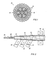
- a well logging cable 10 includes one or more outer strength and armor layer 12 surrounding a plurality of electrical conductors 15.
- a fiber optic core assembly 20 is located at the center of cable 10.
- Core assembly 20 (Fig. 2) includes a solid, soft elastomeric cushioning core 24, formed of a material which transmits forces essentiallly hydrostatically. Materials suitable for this purpose would be any of several elastomers, such as Viton rubber, a flurocarbon elastomer manufactured by Dupont.
- One or more optical fibers 25 are wrapped in a helical spiral about core 24, and a solid, elastomeric cushioning blanket 27, preferably of the same material as core 24, surrounds the fibers and core and cooperates therewith to protect the fibers from point stresses and transmit forces to them essentially hydrostatically.
- a closely and sprially wound tape jacket 30 preferably formed of metal (although the tape may be made of other suitable materials such as various plastics).
- a metal suitable for this purpose would be a precipitation hardening stainless steel such as 75% iron, 16% chromium, 5% nickel, 4% copper, and trace elements.
- Additional or subsequent tape layers 32 are closely wound around the core 24, fibers 25, blanket 27 and first tape layer 30 in the same direction and spaced to overlap the respective preceding spiral cuts 33 and 34 (Fig. 2) of the preceding tape layers.
- the tape layers cooperate with one another and with the blanket and core to buffer the optical fibers from point stresses and other forces within the logging cable and to form a barrier against the entry of moisture into the elastomeric cushioning means and the optical fibers.
- the outermost tape layer 35 is coated with a controlled melting point alloy 36 before it is wound onto the preceding layer. After it is wound onto layers 30 and 32 (and becomes part of core 20) it is passed through an induction heating coil 38 where it is briefly heated to a temperature exceeding the melting point of the alloy coating 36. The alloy melts and fuses to form an even better seal for the core assembly 20 against moisture penetration.
- the controlled melting point alloy 36 is a lead based alloy because lead has enhanced deformation tolerance and water resistance. This is important because of the considerable stretching and bending which a logging cable undergoes during well logging operations. The enormous plastic deformation tolerance of the lead substantially improves the integrity of the fused alloy barrier under these condition.
- a suitable alloy for this coating would be 97.5% lead, 1.5% silver, and 1% tin, having a melting point of 310° C.
- controlled melting point is chosen since the alloy must not melt at borehole temperatures (typically 175% C or higher), and yet must be readily and quickly fused by the induction coil 38 without heat damaging the elements in the fiber optic core assembly 20 (especially the cushioning core 24 and blanket 27).
- the assembly 20 is moved through induction coil 38 quickly so that the outermost tape layer 35 is brought rapidly to the melting point of the alloy coating 36 and then moved away from coil 38 before much heat can penetrate the inner tape layers 32 and 30.
- the heat in the outermost layer 35 then quickly dissipates, or can be force cooled, with little net transfer of heat energy to the interior of the fiber optic core assembly 20.
- the fiber optic core assembly 20 can be used in a variety of cable configurations. It buffers the optical fibers from point stresses both during cable manufacturing and later when in use. It protects the fibers from moisture, and, due to the helical spiral configuration of the fibers, accommodates repeated flexing and stretching of the cable.
- Other means for increasing the length of the optical fibers relative to the cable, such as a zig-zag rather than spiral configuration, may of course be used in the cushioning material (core 24 and blanket 27) to increase the compressibility. Under proper circumstances, even a single tape layer having the fused alloy coating can be considered.
- the cable construction containing the fiber optic core assembly 20 may include other cable members such as conductors 15, armor and strength members 12, and so on, from which the optical fibers 25 are protected and buffered.
Landscapes
- Physics & Mathematics (AREA)
- General Physics & Mathematics (AREA)
- Optics & Photonics (AREA)
- Insulated Conductors (AREA)
- Communication Cables (AREA)
- Surface Treatment Of Glass Fibres Or Filaments (AREA)
Applications Claiming Priority (2)
| Application Number | Priority Date | Filing Date | Title |
|---|---|---|---|
| US06/189,971 US4375313A (en) | 1980-09-22 | 1980-09-22 | Fiber optic cable and core |
| US189971 | 1988-05-04 |
Publications (2)
| Publication Number | Publication Date |
|---|---|
| EP0048674A2 true EP0048674A2 (fr) | 1982-03-31 |
| EP0048674A3 EP0048674A3 (fr) | 1982-06-09 |
Family
ID=22699529
Family Applications (1)
| Application Number | Title | Priority Date | Filing Date |
|---|---|---|---|
| EP81401466A Ceased EP0048674A3 (fr) | 1980-09-22 | 1981-09-22 | Méthode pour préparer une structure centrale à fibres optiques pour un câble pour carottage, ainsi que structure centrale ainsi préparée |
Country Status (4)
| Country | Link |
|---|---|
| US (1) | US4375313A (fr) |
| EP (1) | EP0048674A3 (fr) |
| JP (1) | JPS5786805A (fr) |
| CA (1) | CA1163123A (fr) |
Cited By (8)
| Publication number | Priority date | Publication date | Assignee | Title |
|---|---|---|---|---|
| GB2152235A (en) * | 1981-07-20 | 1985-07-31 | Chevron Res | Armoured optical fibre cable for use in an optical communication system for drill hole logging |
| GB2169427A (en) * | 1984-12-27 | 1986-07-09 | Honda Motor Co Ltd | Locking cable for antitheft devices |
| GB2173034A (en) * | 1985-03-01 | 1986-10-01 | Int Standard Electric Corp | Oil well logging cable |
| GB2177231A (en) * | 1985-06-28 | 1987-01-14 | Fujikura Ltd | A composite overhead cable structure for electric and optical transmission |
| EP0084388B1 (fr) * | 1982-01-14 | 1988-11-23 | Nkf Kabel B.V. | Elément d'un câble optique |
| AU601487B2 (en) * | 1986-09-26 | 1990-09-13 | Alcatel N.V. | Optical cable |
| DE10129558A1 (de) * | 2001-04-21 | 2002-10-24 | Nexans France Sa | Kabel mit einer optische Adern enthaltenden Kabelseele |
| CN113008422A (zh) * | 2020-12-18 | 2021-06-22 | 同济大学 | 一种预应力筋群锚固状态分布式监测结构和方法 |
Families Citing this family (45)
| Publication number | Priority date | Publication date | Assignee | Title |
|---|---|---|---|---|
| GB2105483B (en) | 1980-06-26 | 1985-08-07 | Standard Telephones Cables Ltd | Optical fibre cables |
| US4611748A (en) * | 1981-11-23 | 1986-09-16 | Olin Corporation | Process and apparatus for fabricating optical fiber cables |
| US4515435A (en) * | 1982-08-10 | 1985-05-07 | Cooper Industries, Inc. | Thermally stabilized fiber optic cable |
| SE8206650L (sv) * | 1982-09-01 | 1984-03-02 | Olin Corp | Sett och apparat for sammansettning av en kommunikationskabel med optiska fibrer |
| US4711388A (en) * | 1983-05-24 | 1987-12-08 | Olin Corporation | Process and apparatus for fabricating optical fiber cables |
| US4497537A (en) * | 1983-06-09 | 1985-02-05 | Bicc Public Limited Company | Electric and/or optical cable |
| US4579420A (en) * | 1983-06-16 | 1986-04-01 | Olin Corporation | Two-pole powered ruggedized optical fiber cable and method and apparatus for forming the same |
| JPS6045212A (ja) * | 1983-08-23 | 1985-03-11 | Sumitomo Electric Ind Ltd | 光フアイバケ−ブル |
| US4949894A (en) * | 1984-06-07 | 1990-08-21 | Olin Corporation | Method and apparatus for forming ultra-small optical fiber cable assemblies |
| US4786137A (en) * | 1984-12-31 | 1988-11-22 | Ericsson, Inc. | Optical cable with filling compound and parallel fibers |
| US4802730A (en) * | 1986-11-10 | 1989-02-07 | Olin Corporation | Optical fiber cables for motor vehicle engine compartment applications |
| US4750805A (en) * | 1987-02-11 | 1988-06-14 | The United States Of America As Represented By The Secretary Of The Army | Helically slit high-Z cable sheathing and method of using same |
| JPS63259505A (ja) * | 1987-04-16 | 1988-10-26 | Sumitomo Electric Ind Ltd | 光フアイバ素線撚合せ上の耐熱薄肉テ−プの接続方法 |
| US4832442A (en) * | 1987-07-17 | 1989-05-23 | United Ropeworks (U.S.A.) Inc. | Method and apparatus for aerial installation of fiber optic cables |
| US5133583A (en) * | 1989-04-27 | 1992-07-28 | Siecor Corporation | Method for use of mesh type cable pulling grips |
| US5202944A (en) * | 1990-06-15 | 1993-04-13 | Westech Geophysical, Inc. | Communication and power cable |
| US5140319A (en) * | 1990-06-15 | 1992-08-18 | Westech Geophysical, Inc. | Video logging system having remote power source |
| US5333228A (en) * | 1993-05-21 | 1994-07-26 | Super Vision International Inc. | Lateral illumination fiber optic cable device and method of manufacture |
| US5838860A (en) * | 1993-05-21 | 1998-11-17 | Super Vision International, Inc. | Fiber optic light source apparatus and method |
| US5481635A (en) * | 1994-10-28 | 1996-01-02 | At&T Corp. | Composite distribution cable |
| US5677974A (en) * | 1995-08-28 | 1997-10-14 | Southern New England Telephone Company | Hybrid communications and power cable and distribution method and network using the same |
| US5812719A (en) * | 1996-03-06 | 1998-09-22 | Karl Strorz Gmbh & Co. | Sheath for a flexible fiber optic lightguide, and the lightguide |
| US5913003A (en) * | 1997-01-10 | 1999-06-15 | Lucent Technologies Inc. | Composite fiber optic distribution cable |
| US6233384B1 (en) * | 1999-02-11 | 2001-05-15 | Gore Enterprise Holdings, Inc. | Ruggedized fiber optic cable |
| US6446723B1 (en) * | 1999-06-09 | 2002-09-10 | Schlumberger Technology Corporation | Cable connection to sensors in a well |
| US6960724B2 (en) * | 2002-09-30 | 2005-11-01 | Schlumberger Technology Corporation | Dual stress member conductive cable |
| CN100439650C (zh) * | 2003-06-12 | 2008-12-03 | 上海光导传输技术研究所 | 深井探测光纤传输系统 |
| US7324730B2 (en) * | 2004-05-19 | 2008-01-29 | Schlumberger Technology Corporation | Optical fiber cables for wellbore applications |
| US7235743B2 (en) * | 2005-04-14 | 2007-06-26 | Schlumberger Technology Corporation | Resilient electrical cables |
| US20070297730A1 (en) * | 2006-06-21 | 2007-12-27 | Bringuier Anne G | Optical fiber assemblies having one or more water-swellable members |
| GB0618108D0 (en) * | 2006-09-14 | 2006-10-25 | Technip France Sa | Subsea umbilical |
| US7860362B2 (en) * | 2007-06-08 | 2010-12-28 | Westerngeco L.L.C. | Enhanced fiber optic seismic land cable |
| US7912333B2 (en) * | 2008-02-05 | 2011-03-22 | Schlumberger Technology Corporation | Dual conductor fiber optic cable |
| US8143523B2 (en) * | 2008-10-21 | 2012-03-27 | Baker Hughes Incorporated | Downhole cable with thermally conductive polymer composites |
| EP2769386A4 (fr) | 2011-10-17 | 2016-02-17 | Services Petroliers Schlumberger | Câble à double utilisation doté d'une encapsulation de fibre optique et destiné à être utilisé dans des opérations de puits de forage |
| WO2014004026A1 (fr) | 2012-06-28 | 2014-01-03 | Schlumberger Canada Limited | Câble optoélectrique à puissance élevée doté de multiples chemins d'alimentation et de télémétrie |
| JP2015215448A (ja) * | 2014-05-09 | 2015-12-03 | 株式会社フジクラ | 光ファイバケーブル |
| US11725468B2 (en) | 2015-01-26 | 2023-08-15 | Schlumberger Technology Corporation | Electrically conductive fiber optic slickline for coiled tubing operations |
| US20160215578A1 (en) * | 2015-01-27 | 2016-07-28 | Schlumberger Technology Corporation | Subsurface Deployment for Monitoring Along a Borehole |
| WO2017082904A1 (fr) * | 2015-11-12 | 2017-05-18 | Halliburton Energy Services, Inc. | Ligne filaire améliorée pour données et alimentation |
| US10049789B2 (en) | 2016-06-09 | 2018-08-14 | Schlumberger Technology Corporation | Compression and stretch resistant components and cables for oilfield applications |
| US10670823B2 (en) * | 2016-09-02 | 2020-06-02 | Belden Canada Inc. | Optic cable puller assembly |
| MY201978A (en) * | 2019-09-13 | 2024-03-27 | Petroliam Nasional Berhad | Optical cable |
| IT201900022977A1 (it) * | 2019-12-04 | 2021-06-04 | Prysmian Spa | Cavo elettro-ottico |
| US12557989B2 (en) | 2021-03-12 | 2026-02-24 | Stryker European Operations Limited | Neurosurgical methods and systems for detecting and removing tumorous tissue |
Family Cites Families (21)
| Publication number | Priority date | Publication date | Assignee | Title |
|---|---|---|---|---|
| US298751A (en) * | 1884-05-20 | Fibtji | ||
| US2344501A (en) * | 1942-07-03 | 1944-03-21 | Okonite Co | Electric cable |
| CH529428A (de) * | 1971-03-22 | 1972-10-15 | Bbc Brown Boveri & Cie | Verfahren zur Herstellung eines isolierten Leiters, Vorrichtung zur Durchführung des Verfahrens und Verwendung des isolierten Leiters |
| US3750058A (en) * | 1971-12-08 | 1973-07-31 | Bell Telephone Labor Inc | Waveguide structure utilizing compliant helical support |
| GB1336363A (en) * | 1972-04-26 | 1973-11-07 | Hve Thermoduct Ltd | Armoured cables |
| DE2302662C2 (de) * | 1973-01-19 | 1983-09-01 | Siemens AG, 1000 Berlin und 8000 München | Nachrichtenkabel |
| JPS50156944A (fr) * | 1974-06-07 | 1975-12-18 | ||
| US3955878A (en) * | 1975-02-13 | 1976-05-11 | International Telephone And Telegraph Corporation | Fiber optic transmission line |
| JPS51105835A (en) * | 1975-03-14 | 1976-09-20 | Nippon Telegraph & Telephone | Hikarifuaipakeeburu oyobi sonoseizohoho |
| US4146302A (en) * | 1975-06-02 | 1979-03-27 | General Cable Corporation | Construction of cable made of optical fibres |
| DE2551211B2 (de) * | 1975-11-12 | 1977-12-29 | Siemens AG, 1000 Berlin und 8000 München | Optisches kabel mit mehrschichtigem kunststoffmantel |
| US4054365A (en) * | 1976-05-28 | 1977-10-18 | General Cable Corporation | Fiber optic cable construction |
| GB1547490A (en) * | 1977-07-19 | 1979-06-20 | Post Office | Gables |
| US4147406A (en) * | 1976-10-26 | 1979-04-03 | Belden Corporation | Fiber optic cable |
| GB1589532A (en) * | 1977-02-08 | 1981-05-13 | Smiths Industries Ltd | Fibre-optic cable |
| GB2010528B (en) * | 1977-12-16 | 1982-05-19 | Post Office | Underwater cables |
| IT1092793B (it) * | 1978-02-24 | 1985-07-12 | Pirelli | Cavo sottomarino perfezionato |
| GB1578439A (en) * | 1978-03-22 | 1980-11-05 | Bicc Ltd | Optical cables |
| JPS54134449A (en) * | 1978-04-11 | 1979-10-18 | Kokusai Denshin Denwa Co Ltd | Photoofiber submarine cable |
| JPS619Y2 (fr) * | 1978-06-20 | 1986-01-06 | ||
| DE2907704B2 (de) * | 1979-02-28 | 1981-03-12 | Siemens AG, 1000 Berlin und 8000 München | Verseilelement für optische Kabel |
-
1980
- 1980-09-22 US US06/189,971 patent/US4375313A/en not_active Expired - Lifetime
-
1981
- 1981-09-21 CA CA000386314A patent/CA1163123A/fr not_active Expired
- 1981-09-22 EP EP81401466A patent/EP0048674A3/fr not_active Ceased
- 1981-09-22 JP JP56150492A patent/JPS5786805A/ja active Granted
Cited By (10)
| Publication number | Priority date | Publication date | Assignee | Title |
|---|---|---|---|---|
| GB2152235A (en) * | 1981-07-20 | 1985-07-31 | Chevron Res | Armoured optical fibre cable for use in an optical communication system for drill hole logging |
| EP0084388B1 (fr) * | 1982-01-14 | 1988-11-23 | Nkf Kabel B.V. | Elément d'un câble optique |
| GB2169427A (en) * | 1984-12-27 | 1986-07-09 | Honda Motor Co Ltd | Locking cable for antitheft devices |
| GB2173034A (en) * | 1985-03-01 | 1986-10-01 | Int Standard Electric Corp | Oil well logging cable |
| GB2177231A (en) * | 1985-06-28 | 1987-01-14 | Fujikura Ltd | A composite overhead cable structure for electric and optical transmission |
| GB2177231B (en) * | 1985-06-28 | 1989-07-26 | Fujikura Ltd | A composite overhead cable structure for electric and optical transmission |
| AU601487B2 (en) * | 1986-09-26 | 1990-09-13 | Alcatel N.V. | Optical cable |
| DE10129558A1 (de) * | 2001-04-21 | 2002-10-24 | Nexans France Sa | Kabel mit einer optische Adern enthaltenden Kabelseele |
| CN113008422A (zh) * | 2020-12-18 | 2021-06-22 | 同济大学 | 一种预应力筋群锚固状态分布式监测结构和方法 |
| CN113008422B (zh) * | 2020-12-18 | 2022-04-01 | 同济大学 | 一种预应力筋群锚固状态分布式监测结构和方法 |
Also Published As
| Publication number | Publication date |
|---|---|
| JPH0216485B2 (fr) | 1990-04-17 |
| US4375313A (en) | 1983-03-01 |
| EP0048674A3 (fr) | 1982-06-09 |
| CA1163123A (fr) | 1984-03-06 |
| JPS5786805A (en) | 1982-05-31 |
Similar Documents
| Publication | Publication Date | Title |
|---|---|---|
| US4375313A (en) | Fiber optic cable and core | |
| EP0471600B1 (fr) | Procédé pour fabriquer un câble pour la transmission de données | |
| US9201207B2 (en) | Packaging for encasing an optical fiber in a cable | |
| CA1221861A (fr) | Cable blinde enveloppant un tube hermetiquement scelle sur une fibre optique | |
| EP3398195B1 (fr) | Câble de fond de trou à diamètre réduit | |
| US5894104A (en) | Coax-slickline cable for use in well logging | |
| CA2172652C (fr) | Cable pour diagraphie de sondage a conducteur a fibres optiques et conducteur electrique combines | |
| US4577925A (en) | Optical fiber communication cables and method and apparatus for assembling same | |
| US20180226174A1 (en) | Wireline operations with compacted conducter(s) | |
| CA2259719C (fr) | Cable optique de diagraphie de puits | |
| US6690866B2 (en) | Optical fiber cable for use in harsh environments | |
| US5212755A (en) | Armored fiber optic cables | |
| DE68926279T2 (de) | Elektrooptisches mechanisches Kabel für faseroptische Nachrichtensysteme | |
| CN201229797Y (zh) | 用于电缆组件的铠装组件系统 | |
| CA1041278A (fr) | Methode et materiel pour le faconnage de cables armes | |
| US20080031578A1 (en) | Packaging for encasing an optical fiber in a cable | |
| US4141623A (en) | Optical fibre cable and a method of manufacture | |
| JPS61209409A (ja) | 光フアイバ通信海底ケーブル | |
| US20030169179A1 (en) | Downhole data transmisssion line | |
| CA1225208A (fr) | Fabrication d'une ame de cable a fibres optiques | |
| GB2321973A (en) | Well logging cable with optic fibre in metal tube with conductive liner | |
| AU563499B2 (en) | A hermetically sealed tube incorporating an optical fiber surrounded by an armored cable | |
| CA1229722A (fr) | Methode de fabrication de cables a fibres optiques | |
| JPS5999403A (ja) | 通信ケ−ブル及びその製造方法 | |
| GB2164469A (en) | Optical fibre cables |
Legal Events
| Date | Code | Title | Description |
|---|---|---|---|
| PUAI | Public reference made under article 153(3) epc to a published international application that has entered the european phase |
Free format text: ORIGINAL CODE: 0009012 |
|
| AK | Designated contracting states |
Designated state(s): DE FR GB IT NL SE |
|
| PUAL | Search report despatched |
Free format text: ORIGINAL CODE: 0009013 |
|
| AK | Designated contracting states |
Designated state(s): DE FR GB IT NL SE |
|
| 17P | Request for examination filed |
Effective date: 19821122 |
|
| STAA | Information on the status of an ep patent application or granted ep patent |
Free format text: STATUS: THE APPLICATION HAS BEEN REFUSED |
|
| 18R | Application refused |
Effective date: 19841221 |
|
| RIN1 | Information on inventor provided before grant (corrected) |
Inventor name: SHAPIRO, ROBERT MARVIN Inventor name: ANDERSON, RONALD ALVIN |