EP0048694A2 - Système de conduites - Google Patents
Système de conduites Download PDFInfo
- Publication number
- EP0048694A2 EP0048694A2 EP81810381A EP81810381A EP0048694A2 EP 0048694 A2 EP0048694 A2 EP 0048694A2 EP 81810381 A EP81810381 A EP 81810381A EP 81810381 A EP81810381 A EP 81810381A EP 0048694 A2 EP0048694 A2 EP 0048694A2
- Authority
- EP
- European Patent Office
- Prior art keywords
- elements
- profiles
- heat exchanger
- support
- support profiles
- Prior art date
- Legal status (The legal status is an assumption and is not a legal conclusion. Google has not performed a legal analysis and makes no representation as to the accuracy of the status listed.)
- Withdrawn
Links
Images




Classifications
-
- F—MECHANICAL ENGINEERING; LIGHTING; HEATING; WEAPONS; BLASTING
- F24—HEATING; RANGES; VENTILATING
- F24S—SOLAR HEAT COLLECTORS; SOLAR HEAT SYSTEMS
- F24S25/00—Arrangement of stationary mountings or supports for solar heat collector modules
- F24S25/60—Fixation means, e.g. fasteners, specially adapted for supporting solar heat collector modules
- F24S25/63—Fixation means, e.g. fasteners, specially adapted for supporting solar heat collector modules for fixing modules or their peripheral frames to supporting elements
- F24S25/634—Clamps; Clips
- F24S25/636—Clamps; Clips clamping by screw-threaded elements
-
- F—MECHANICAL ENGINEERING; LIGHTING; HEATING; WEAPONS; BLASTING
- F24—HEATING; RANGES; VENTILATING
- F24S—SOLAR HEAT COLLECTORS; SOLAR HEAT SYSTEMS
- F24S10/00—Solar heat collectors using working fluids
- F24S10/50—Solar heat collectors using working fluids the working fluids being conveyed between plates
- F24S10/502—Solar heat collectors using working fluids the working fluids being conveyed between plates having conduits formed by paired plates and internal partition means
-
- F—MECHANICAL ENGINEERING; LIGHTING; HEATING; WEAPONS; BLASTING
- F24—HEATING; RANGES; VENTILATING
- F24S—SOLAR HEAT COLLECTORS; SOLAR HEAT SYSTEMS
- F24S10/00—Solar heat collectors using working fluids
- F24S10/70—Solar heat collectors using working fluids the working fluids being conveyed through tubular absorbing conduits
- F24S10/73—Solar heat collectors using working fluids the working fluids being conveyed through tubular absorbing conduits the tubular conduits being of plastic material
-
- F—MECHANICAL ENGINEERING; LIGHTING; HEATING; WEAPONS; BLASTING
- F24—HEATING; RANGES; VENTILATING
- F24S—SOLAR HEAT COLLECTORS; SOLAR HEAT SYSTEMS
- F24S20/00—Solar heat collectors specially adapted for particular uses or environments
- F24S20/40—Solar heat collectors combined with other heat sources, e.g. using electrical heating or heat from ambient air
-
- F—MECHANICAL ENGINEERING; LIGHTING; HEATING; WEAPONS; BLASTING
- F24—HEATING; RANGES; VENTILATING
- F24S—SOLAR HEAT COLLECTORS; SOLAR HEAT SYSTEMS
- F24S20/00—Solar heat collectors specially adapted for particular uses or environments
- F24S20/60—Solar heat collectors integrated in fixed constructions, e.g. in buildings
- F24S20/67—Solar heat collectors integrated in fixed constructions, e.g. in buildings in the form of roof constructions
-
- F—MECHANICAL ENGINEERING; LIGHTING; HEATING; WEAPONS; BLASTING
- F24—HEATING; RANGES; VENTILATING
- F24S—SOLAR HEAT COLLECTORS; SOLAR HEAT SYSTEMS
- F24S25/00—Arrangement of stationary mountings or supports for solar heat collector modules
- F24S25/30—Arrangement of stationary mountings or supports for solar heat collector modules using elongate rigid mounting elements extending substantially along the supporting surface, e.g. for covering buildings with solar heat collectors
- F24S25/33—Arrangement of stationary mountings or supports for solar heat collector modules using elongate rigid mounting elements extending substantially along the supporting surface, e.g. for covering buildings with solar heat collectors forming substantially planar assemblies, e.g. of coplanar or stacked profiles
-
- F—MECHANICAL ENGINEERING; LIGHTING; HEATING; WEAPONS; BLASTING
- F24—HEATING; RANGES; VENTILATING
- F24S—SOLAR HEAT COLLECTORS; SOLAR HEAT SYSTEMS
- F24S25/00—Arrangement of stationary mountings or supports for solar heat collector modules
- F24S25/60—Fixation means, e.g. fasteners, specially adapted for supporting solar heat collector modules
- F24S25/61—Fixation means, e.g. fasteners, specially adapted for supporting solar heat collector modules for fixing to the ground or to building structures
- F24S25/613—Fixation means, e.g. fasteners, specially adapted for supporting solar heat collector modules for fixing to the ground or to building structures in the form of bent strips or assemblies of strips; Hook-like connectors; Connectors to be mounted between building-covering elements
-
- F—MECHANICAL ENGINEERING; LIGHTING; HEATING; WEAPONS; BLASTING
- F24—HEATING; RANGES; VENTILATING
- F24S—SOLAR HEAT COLLECTORS; SOLAR HEAT SYSTEMS
- F24S25/00—Arrangement of stationary mountings or supports for solar heat collector modules
- F24S25/60—Fixation means, e.g. fasteners, specially adapted for supporting solar heat collector modules
- F24S25/65—Fixation means, e.g. fasteners, specially adapted for supporting solar heat collector modules for coupling adjacent supporting elements, e.g. for connecting profiles together
-
- F—MECHANICAL ENGINEERING; LIGHTING; HEATING; WEAPONS; BLASTING
- F24—HEATING; RANGES; VENTILATING
- F24S—SOLAR HEAT COLLECTORS; SOLAR HEAT SYSTEMS
- F24S40/00—Safety or protection arrangements of solar heat collectors; Preventing malfunction of solar heat collectors
- F24S40/80—Accommodating differential expansion of solar collector elements
-
- F—MECHANICAL ENGINEERING; LIGHTING; HEATING; WEAPONS; BLASTING
- F24—HEATING; RANGES; VENTILATING
- F24S—SOLAR HEAT COLLECTORS; SOLAR HEAT SYSTEMS
- F24S80/00—Details, accessories or component parts of solar heat collectors not provided for in groups F24S10/00-F24S70/00
- F24S80/30—Arrangements for connecting the fluid circuits of solar collectors with each other or with other components, e.g. pipe connections; Fluid distributing means, e.g. headers
-
- F—MECHANICAL ENGINEERING; LIGHTING; HEATING; WEAPONS; BLASTING
- F24—HEATING; RANGES; VENTILATING
- F24S—SOLAR HEAT COLLECTORS; SOLAR HEAT SYSTEMS
- F24S80/00—Details, accessories or component parts of solar heat collectors not provided for in groups F24S10/00-F24S70/00
- F24S80/60—Thermal insulation
-
- F—MECHANICAL ENGINEERING; LIGHTING; HEATING; WEAPONS; BLASTING
- F24—HEATING; RANGES; VENTILATING
- F24S—SOLAR HEAT COLLECTORS; SOLAR HEAT SYSTEMS
- F24S25/00—Arrangement of stationary mountings or supports for solar heat collector modules
- F24S2025/80—Special profiles
- F24S2025/804—U-, C- or O-shaped; Hat profiles
-
- Y—GENERAL TAGGING OF NEW TECHNOLOGICAL DEVELOPMENTS; GENERAL TAGGING OF CROSS-SECTIONAL TECHNOLOGIES SPANNING OVER SEVERAL SECTIONS OF THE IPC; TECHNICAL SUBJECTS COVERED BY FORMER USPC CROSS-REFERENCE ART COLLECTIONS [XRACs] AND DIGESTS
- Y02—TECHNOLOGIES OR APPLICATIONS FOR MITIGATION OR ADAPTATION AGAINST CLIMATE CHANGE
- Y02B—CLIMATE CHANGE MITIGATION TECHNOLOGIES RELATED TO BUILDINGS, e.g. HOUSING, HOUSE APPLIANCES OR RELATED END-USER APPLICATIONS
- Y02B10/00—Integration of renewable energy sources in buildings
- Y02B10/20—Solar thermal
-
- Y—GENERAL TAGGING OF NEW TECHNOLOGICAL DEVELOPMENTS; GENERAL TAGGING OF CROSS-SECTIONAL TECHNOLOGIES SPANNING OVER SEVERAL SECTIONS OF THE IPC; TECHNICAL SUBJECTS COVERED BY FORMER USPC CROSS-REFERENCE ART COLLECTIONS [XRACs] AND DIGESTS
- Y02—TECHNOLOGIES OR APPLICATIONS FOR MITIGATION OR ADAPTATION AGAINST CLIMATE CHANGE
- Y02E—REDUCTION OF GREENHOUSE GAS [GHG] EMISSIONS, RELATED TO ENERGY GENERATION, TRANSMISSION OR DISTRIBUTION
- Y02E10/00—Energy generation through renewable energy sources
- Y02E10/40—Solar thermal energy, e.g. solar towers
- Y02E10/44—Heat exchange systems
-
- Y—GENERAL TAGGING OF NEW TECHNOLOGICAL DEVELOPMENTS; GENERAL TAGGING OF CROSS-SECTIONAL TECHNOLOGIES SPANNING OVER SEVERAL SECTIONS OF THE IPC; TECHNICAL SUBJECTS COVERED BY FORMER USPC CROSS-REFERENCE ART COLLECTIONS [XRACs] AND DIGESTS
- Y02—TECHNOLOGIES OR APPLICATIONS FOR MITIGATION OR ADAPTATION AGAINST CLIMATE CHANGE
- Y02E—REDUCTION OF GREENHOUSE GAS [GHG] EMISSIONS, RELATED TO ENERGY GENERATION, TRANSMISSION OR DISTRIBUTION
- Y02E10/00—Energy generation through renewable energy sources
- Y02E10/40—Solar thermal energy, e.g. solar towers
- Y02E10/47—Mountings or tracking
Definitions
- the present invention relates to a vessel system for a heat transfer medium, in particular an environmental heat exchanger, with flat heat exchanger elements.
- heat exchangers are known and they either serve as solar collectors or as pure heat exchangers in connection with a heat pump. They are preferably arranged on a roof and are used to absorb heat from the ambient air, possibly also to give off heat to the environment when the heat pump is used to cool rooms in an air conditioning system.
- the present invention has for its object to solve these problems with a simple and quick to assemble system.
- the solution is that the heat exchanger elements are arranged on carrier profiles so that they can be moved in any direction.
- the heat exchanger elements are preferably connected to the support profiles by means of cross-slide-type assembly members. It is a tensile and pressure resistant connection between the heat transfer elements and the Support profiles reached and yet the heat exchanger elements can expand and contract as desired.
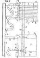
- FIG. 1 shows two elements 1 of a heat exchanger.
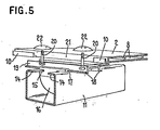
- Each of these elements consists of a number of flat hollow profiles 2 made of plastic, which are provided with parallel channels 3, as shown in particular in Figures 2 and 5.
- Each hollow profile is connected at both ends to a connecting piece 4, which is provided with connecting channels 5, which connect the individual channels 3 of the hollow profile in series connection.
- Each connecting piece 4 is provided with a connecting piece 6, to which a flexible, non-kinkable hose bend 7 is connected, the other end of which is connected to a connecting piece 8, a forward or return manifold 9.
- the hollow profiles 2 are provided on the narrow sides with L-shaped connecting strips lo, which interlock for the mutual connection of adjacent hollow profiles 2 (FIG. 5)
- the heat exchanger elements are on support professionals len 11 mounted, which are mounted according to Figure 3 and Figure 4 by means of roof hooks 12 in the fall line of the roof, the bricks 13 are only indicated in Figure 3 for the sake of simplicity.
- the carrier profiles 11 are open rectangular profiles at the top and their inwardly directed flanges 14 engage with a little play in the slots 15 of an approximately semi-cylindrical lower part 16 of a coupling member.
- the lower parts 16 have slots 17 which extend transversely to the slots 15 and into which outwardly directed flanges 18 of an upper part 19 of the connecting element engage in a freely displaceable manner with some play.
- the upper part is a profile of approximately H-shaped cross section, with the web of which screws are screwed 2o. These setscrews project through a gap 21 (FIG. 5) created by milling out the connecting strips 10, between adjacent hollow profiles 2.
- Counter nuts 22 are screwed onto the two threaded pins from above and have holes at the top to which a special wrench can be attached to tighten them.
- the hollow profiles are thus firmly connected in places to the upper parts 19 of the assembly element. Similar to a cross slide, this mounting member permits relative movements between the hollow profiles 2 and the carrier profiles 11 in two directions perpendicular to one another, ie relative movements in any direction are possible.
- simple support elements 23 (FIG. 3) are screwed to the support profiles 11, on which the hollow profiles 2 rest loosely and at the desired distance are held by the carrier profiles.
- the assembly members and support members can be inserted and tightened from one end of the carrier profiles 11, which allows quick, easy assembly.
- the heat exchanger elements must be inclined Arrangement be secured against sliding on the carrier profiles 11.
- stop screws 24 are screwed to the carrier profiles 11 at the upper ends of each heat exchanger element for this purpose, against which the lower parts of mounting elements lying at the same height abut and the heat exchanger element slides prevent.
- the supply and return manifolds 9 are each held in a U-shaped holding profile 25 which is mounted by means of roof brackets 26.
- one leg of the holding profile has 25 gaps, as shown in FIG. 6. From the same figure it can be seen that 25 reinforcing plates 27, 28 and 29 are welded onto one end of the holding profile.
- a sheet 3o welded to the manifold 9 and thus secures the manifold against sliding out of the holding profile 25.
- the sheet 28 also serves to anchor a fastening screw for the roof bracket 26.
- the sheet 29 serves to support a screw Attachment of a cross member 31.
- These cross members 31 are, as shown in FIG. 4, also attached to the adjacent roof hooks 12. They serve to support a side cover 32 for the collecting lines 9, the hose bends 7, and the connecting pieces 6 and 8 connected to them. In FIG. 1, the cover is only shown on one side. Cover profiles 33 are also attached to the long sides of the heat exchanger elements and fastened to the carrier profiles 11.
- the heat exchanger shown allows all its parts to be freely diluted in any direction.
- the gaps between individual elements constructed from several hollow profiles 2 also serve this purpose.
- the relatively large-area heat exchanger is securely anchored against tensile and compressive forces. Nevertheless, its construction and assembly are simple, even on existing buildings, especially roofs.
- the load-bearing elements 11 and 25 can be easily assembled and then the assembly members 16, 19 can be pushed in, the heat exchanger elements 1 placed and screwed tight.
- the connections are also easy to create.
- the arrangement of the heat exchanger elements 1 at a distance from the existing building, for example roof, has the advantage that the ambient air can circulate above and below the elements 1, which allows a particularly intensive heat exchange.
- a temperature of the ambient air of plus 3 ° C, for example, 35o Kcal / h per m2 of heat exchange surface "can be exchanged.
- the heat exchanger on an inclined tiled roof
- it can be attached to any other surface, for example on a flat roof, on a building wall, on an embankment or otherwise, e.g. can be arranged as a fence or privacy screen.
- the assembly of the heat exchanger is particularly simple.
- the weight of the profiles is low, and these can generally be assembled and assembled by hand without mechanical aids.
- the weight of the installed heat exchanger elements is around 2o Kg / m2 and the weight of a 3o cm wide and 11m long profile filled with heat transfer medium is 3o Kg, so that it can be easily transported and laid by hand even under somewhat difficult conditions is.
- the heat exchangers arranged at a distance from an existing structure, for example a roof can be effective on both sides. This is essential when the outside temperatures are low. In summer with direct sunlight, however, it would be advantageous to operate the heat exchangers more in the sense of solar collectors, in which case it would be desirable to insulate the space under the heat exchanger.
- inflatable sealing hoses can be arranged along the edges of the heat exchanger elements, which are inflated in hot weather to produce a closed, insulating air cushion under the elements.
- 3 shows a suitable inflatable tube 34 in the non-pressurized state in the solid line and in the inflated state in contact with the roof in the dash-dotted line. So far it has been assumed that several profiles 2 are always coupled to form larger exchange elements. However, it is also possible, for example, to arrange individual profiles in a suitable inclination (for example 35 ° ) on a flat roof parallel to one another with respect to the roof.
- the profiles 2 can also be used in a different form as a heat exchanger, e.g. as a ceiling heater in a room. As mentioned at the beginning, they can be used for heating or cooling, and one and the same heat pump can be used to selectively use the heat exchanger located in the interior or mounted on the outside for extracting or giving off heat.
- FIGS 7 and 8 show an embodiment in which a profile 2 is formed into a spiral or screw and held in a cage.
- the cage has an upper cross 40 made of metal profiles and a lower cross 41 made of metal profiles.
- One arm of the lower cross 41 consists of two parallel hollow profiles 41a and 41b with which the flow and return lines 42 and 43 of the heat transfer circuit are connected.
- flexible connecting lines 44 and 45 are connected, which are connected to the connecting pieces 4 at the ends of the spiral of the profile 2.
- the two crosses 4o and 41 are connected by rods 46, the ends of the profile 2 each being held between two rods, while the other turns of the profile 2 each abut against a rod lying outside the profile.
- the spiral is thus held movably in the cage formed by the crosses 40 and 41 and the bars 46 in such a way that it can carry out the considerable expansions and coneactions with large temperature differences without hindrance.
- the embodiment according to FIGS. 7 and 8 has the considerable advantage that it can be set up anywhere in front of the house, for example in the garden, without a building permit.
- it is preferably placed on base 47 so that the ambient air can circulate freely through the spiral.
- the opening of the spiral can also be placed in the main wind direction so that optimal ventilation and maximum heat exchange are achieved.
- An exchanger according to Fig. 7 and 8 is relatively light and can be moved manually without any lifting equipment.
- spirals can be stacked on top of each other by screwing the lower cross 41 of the upper spiral to the upper cross 4o of the lower spiral, but of course any number of spirals can be placed next to each other and connected in parallel or in series in the heat transfer circuit.
- the installation of the heat exchanger outdoors also allows the installation of a burner or internal combustion engine without the need for a chimney. It can thus be in the free space in the center of the spiral, a burner in the combustion chamber assembly of a boiler, for example, be arranged, which allows in cold weather to reheat for example at temperatures below 0 C + 2.
- the burner can also be used for heat pump in the center of the spiral.
- both an internal combustion engine as a heat pump driven by the same, wherein the waste heat of the engine either is used all over the spiral or in some cases a particular heat exchanger.
- a fan can also be provided to intensify the ventilation of the spiral.
- the heat exchanger can also be placed in water, waste water. Snow is not a problem because it falls through the spiral and does not hinder heat transfer or heating by the sun.
- profile 2 with one tier of chambers
- a profile with two or three tiers of chambers can also be used, e.g.
- the exhaust gases from a burner or motor can be passed through a middle level of chambers, while the heat transfer medium of the heat pump circulates on the outer levels.
Landscapes
- Engineering & Computer Science (AREA)
- Physics & Mathematics (AREA)
- Life Sciences & Earth Sciences (AREA)
- Sustainable Development (AREA)
- Sustainable Energy (AREA)
- Thermal Sciences (AREA)
- Chemical & Material Sciences (AREA)
- Combustion & Propulsion (AREA)
- Mechanical Engineering (AREA)
- General Engineering & Computer Science (AREA)
- Heat-Exchange Devices With Radiators And Conduit Assemblies (AREA)
Applications Claiming Priority (2)
| Application Number | Priority Date | Filing Date | Title |
|---|---|---|---|
| CH7112/80 | 1980-09-23 | ||
| CH711280 | 1980-09-23 |
Publications (2)
| Publication Number | Publication Date |
|---|---|
| EP0048694A2 true EP0048694A2 (fr) | 1982-03-31 |
| EP0048694A3 EP0048694A3 (fr) | 1982-09-29 |
Family
ID=4320157
Family Applications (1)
| Application Number | Title | Priority Date | Filing Date |
|---|---|---|---|
| EP81810381A Withdrawn EP0048694A3 (fr) | 1980-09-23 | 1981-09-16 | Système de conduites |
Country Status (1)
| Country | Link |
|---|---|
| EP (1) | EP0048694A3 (fr) |
Cited By (4)
| Publication number | Priority date | Publication date | Assignee | Title |
|---|---|---|---|---|
| EP0674141A3 (fr) * | 1994-03-25 | 1996-03-06 | Friedrich Mueller | Panneau pour collecteur solaire. |
| WO2012140565A3 (fr) * | 2011-04-13 | 2013-06-27 | Magen Eco-Energy (A.C.S.) Ltd. | Collecteur solaire |
| EP2982915A1 (fr) * | 2014-08-04 | 2016-02-10 | Robert Bosch Gmbh | Unité de toit, système de toiture et procédé de montage d'un tel système de toiture |
| CN106766236A (zh) * | 2016-12-21 | 2017-05-31 | 天津全阳科技有限公司 | 家装用集成热水器 |
Family Cites Families (8)
| Publication number | Priority date | Publication date | Assignee | Title |
|---|---|---|---|---|
| US3544049A (en) * | 1968-10-09 | 1970-12-01 | Gen Electric | Evaporator support bracket for water coolers |
| US4006731A (en) * | 1974-10-18 | 1977-02-08 | Decks, Incorporated | Building deck construction |
| DE2645072A1 (de) * | 1976-10-06 | 1978-04-13 | Karlheinz Dr Rer Nat Raetz | Waermeaustauscher aus stegdoppelbaendern fuer heizsysteme mit niedriger vorlauftemperatur |
| DE2712446A1 (de) * | 1977-03-22 | 1978-09-28 | Hans Viessmann | Halte- und tragvorrichtung fuer die befestigung von sonnenkollektorelementen |
| GB2000860B (en) * | 1977-07-06 | 1982-08-04 | Showa Aluminium Co Ltd | Solar collector |
| DE2733172A1 (de) * | 1977-07-22 | 1979-02-01 | Progress Consult Untersuchunge | Vorrichtung zur waermegewinnung |
| FR2401290A1 (fr) * | 1977-08-25 | 1979-03-23 | Saint Gobain | Dispositif de montage de capteurs solaires sur les batiments |
| US4246872A (en) * | 1979-04-30 | 1981-01-27 | General Electric Company | Heat exchanger tube support |
-
1981
- 1981-09-16 EP EP81810381A patent/EP0048694A3/fr not_active Withdrawn
Cited By (5)
| Publication number | Priority date | Publication date | Assignee | Title |
|---|---|---|---|---|
| EP0674141A3 (fr) * | 1994-03-25 | 1996-03-06 | Friedrich Mueller | Panneau pour collecteur solaire. |
| WO2012140565A3 (fr) * | 2011-04-13 | 2013-06-27 | Magen Eco-Energy (A.C.S.) Ltd. | Collecteur solaire |
| EP2982915A1 (fr) * | 2014-08-04 | 2016-02-10 | Robert Bosch Gmbh | Unité de toit, système de toiture et procédé de montage d'un tel système de toiture |
| CN106766236A (zh) * | 2016-12-21 | 2017-05-31 | 天津全阳科技有限公司 | 家装用集成热水器 |
| CN106766236B (zh) * | 2016-12-21 | 2019-07-05 | 天津全阳科技有限公司 | 家装用集成热水器 |
Also Published As
| Publication number | Publication date |
|---|---|
| EP0048694A3 (fr) | 1982-09-29 |
Similar Documents
| Publication | Publication Date | Title |
|---|---|---|
| DE3042952A1 (de) | Als sonnenwaermekollektor fungierendes bauelement | |
| DE2702939A1 (de) | Blechabdeckung fuer daecher | |
| DE2733899A1 (de) | Bausatz fuer klimadaecher oder klimafassaden | |
| EP2218970B1 (fr) | Système d'équilibrage des températures | |
| CH630458A5 (de) | Waermeaustauscher, insbesondere zum heizen oder kuehlen eines raumes, und verwendung des waermeaustauschers. | |
| DE2712532A1 (de) | Solarheizungsbausatz | |
| EP0048694A2 (fr) | Système de conduites | |
| DE3147124C2 (de) | Rohrbündel-Wärmetauscher | |
| DE3026217A1 (de) | Vorrichtung zur erwaermung einer fluessigkeit unter ausnutzung der sonnenenergie | |
| EP4431832A1 (fr) | Système et procédé d'utilisation simultanée ciblée de rayonnement solaire pour la production d'énergie électrique et le chauffage d'un circuit de fluide | |
| DE3046380A1 (de) | Waermesammlersystem fuer ein energiedach oder eine energiefassade | |
| CH635666A5 (en) | Ceiling radiator heating unit in hall-like rooms | |
| DE3022521A1 (de) | Luftkollektor fuer eine waermepumpenanlage o.dgl. | |
| DE2937071A1 (de) | Verfahren zur rueckgewinnung der transmissionswaermeverluste bei gebaeuden aller art, sowie konstruktionsvorschlaege fuer solche gebaeude | |
| CH685645A5 (de) | Deckenstrahlkörper. | |
| DE3016436A1 (de) | Zu einer schallschutzwand, vorzugsweise zwischen pfosten anordenbare schallschutzelemente | |
| DE2359446A1 (de) | Flaechenheizung fuer gebaeude und freiflaechen | |
| EP0932799B1 (fr) | Immeuble avec un systeme de chauffage | |
| DE3147632C2 (de) | Anordnung zur Absorption von Umweltenergie an einer Gebäudeaußenwand | |
| DE2708128A1 (de) | Fassadenelement fuer eine gebaeude- vorhangwand | |
| DE2926931C2 (de) | Wärmeversorgungssystem mittels vorgefertigter Solarabsorber im Baukastensystem | |
| DE3210215A1 (de) | Waermepumpen - aussenabsorber - verdampfersystem fuer fassaden, hausdaecher, zaeune oder dgl. | |
| DE2557639A1 (de) | Fertighaus | |
| DE2743023A1 (de) | Anlage zur nutzung von umgebungswaerme | |
| DE3148480A1 (de) | Vorrichtung zur temperaturregelung eines gebaeudes und bauelement zur verwendung in einer derartigen vorrichtung |
Legal Events
| Date | Code | Title | Description |
|---|---|---|---|
| PUAI | Public reference made under article 153(3) epc to a published international application that has entered the european phase |
Free format text: ORIGINAL CODE: 0009012 |
|
| AK | Designated contracting states |
Designated state(s): AT DE FR GB IT |
|
| PUAL | Search report despatched |
Free format text: ORIGINAL CODE: 0009013 |
|
| AK | Designated contracting states |
Designated state(s): AT DE FR GB IT |
|
| 17P | Request for examination filed |
Effective date: 19821015 |
|
| STAA | Information on the status of an ep patent application or granted ep patent |
Free format text: STATUS: THE APPLICATION IS DEEMED TO BE WITHDRAWN |
|
| 18D | Application deemed to be withdrawn |
Effective date: 19831109 |