EP0048701A1 - Verfahren zur Herstellung eines Anschlussnippels - Google Patents
Verfahren zur Herstellung eines Anschlussnippels Download PDFInfo
- Publication number
- EP0048701A1 EP0048701A1 EP81830162A EP81830162A EP0048701A1 EP 0048701 A1 EP0048701 A1 EP 0048701A1 EP 81830162 A EP81830162 A EP 81830162A EP 81830162 A EP81830162 A EP 81830162A EP 0048701 A1 EP0048701 A1 EP 0048701A1
- Authority
- EP
- European Patent Office
- Prior art keywords
- section
- tube
- deformation
- thickness
- stamp
- Prior art date
- Legal status (The legal status is an assumption and is not a legal conclusion. Google has not performed a legal analysis and makes no representation as to the accuracy of the status listed.)
- Granted
Links
- 238000004519 manufacturing process Methods 0.000 title claims abstract description 5
- 238000000034 method Methods 0.000 claims abstract description 28
- 239000000463 material Substances 0.000 claims description 24
- 239000011159 matrix material Substances 0.000 claims description 10
- 229910000831 Steel Inorganic materials 0.000 claims description 8
- 230000006835 compression Effects 0.000 claims description 8
- 238000007906 compression Methods 0.000 claims description 8
- 239000010959 steel Substances 0.000 claims description 8
- 230000008569 process Effects 0.000 claims description 6
- 238000005452 bending Methods 0.000 claims description 5
- 230000009467 reduction Effects 0.000 claims description 4
- 238000005520 cutting process Methods 0.000 claims description 3
- 238000003466 welding Methods 0.000 claims description 3
- NINIDFKCEFEMDL-UHFFFAOYSA-N Sulfur Chemical compound [S] NINIDFKCEFEMDL-UHFFFAOYSA-N 0.000 claims description 2
- 230000008878 coupling Effects 0.000 claims description 2
- 238000010168 coupling process Methods 0.000 claims description 2
- 238000005859 coupling reaction Methods 0.000 claims description 2
- 239000000203 mixture Substances 0.000 claims description 2
- 229910052717 sulfur Inorganic materials 0.000 claims description 2
- 239000011593 sulfur Substances 0.000 claims description 2
- 230000004323 axial length Effects 0.000 claims 2
- 238000006073 displacement reaction Methods 0.000 claims 1
- 239000011265 semifinished product Substances 0.000 description 9
- 239000000047 product Substances 0.000 description 6
- 238000003754 machining Methods 0.000 description 5
- 240000008042 Zea mays Species 0.000 description 3
- 230000000694 effects Effects 0.000 description 3
- 229910001369 Brass Inorganic materials 0.000 description 2
- 229910001018 Cast iron Inorganic materials 0.000 description 2
- XEEYBQQBJWHFJM-UHFFFAOYSA-N Iron Chemical compound [Fe] XEEYBQQBJWHFJM-UHFFFAOYSA-N 0.000 description 2
- 230000009471 action Effects 0.000 description 2
- 230000000712 assembly Effects 0.000 description 2
- 238000000429 assembly Methods 0.000 description 2
- 230000015572 biosynthetic process Effects 0.000 description 2
- 239000010951 brass Substances 0.000 description 2
- 238000010438 heat treatment Methods 0.000 description 2
- 239000004606 Fillers/Extenders Substances 0.000 description 1
- 229910001296 Malleable iron Inorganic materials 0.000 description 1
- 241001590701 Vidia Species 0.000 description 1
- 238000005266 casting Methods 0.000 description 1
- 239000000470 constituent Substances 0.000 description 1
- 230000007423 decrease Effects 0.000 description 1
- 238000012938 design process Methods 0.000 description 1
- 238000009826 distribution Methods 0.000 description 1
- 238000001125 extrusion Methods 0.000 description 1
- 230000002349 favourable effect Effects 0.000 description 1
- 239000000835 fiber Substances 0.000 description 1
- 238000010304 firing Methods 0.000 description 1
- 238000009776 industrial production Methods 0.000 description 1
- 230000000977 initiatory effect Effects 0.000 description 1
- 229910052742 iron Inorganic materials 0.000 description 1
- 239000000314 lubricant Substances 0.000 description 1
- 238000012986 modification Methods 0.000 description 1
- 230000004048 modification Effects 0.000 description 1
- 238000000465 moulding Methods 0.000 description 1
- 239000008188 pellet Substances 0.000 description 1
- 238000004321 preservation Methods 0.000 description 1
- 238000007789 sealing Methods 0.000 description 1
- 239000000126 substance Substances 0.000 description 1
Images


Classifications
-
- B—PERFORMING OPERATIONS; TRANSPORTING
- B21—MECHANICAL METAL-WORKING WITHOUT ESSENTIALLY REMOVING MATERIAL; PUNCHING METAL
- B21D—WORKING OR PROCESSING OF SHEET METAL OR METAL TUBES, RODS OR PROFILES WITHOUT ESSENTIALLY REMOVING MATERIAL; PUNCHING METAL
- B21D53/00—Making other particular articles
- B21D53/24—Making other particular articles nuts or like thread-engaging members
-
- B—PERFORMING OPERATIONS; TRANSPORTING
- B21—MECHANICAL METAL-WORKING WITHOUT ESSENTIALLY REMOVING MATERIAL; PUNCHING METAL
- B21D—WORKING OR PROCESSING OF SHEET METAL OR METAL TUBES, RODS OR PROFILES WITHOUT ESSENTIALLY REMOVING MATERIAL; PUNCHING METAL
- B21D41/00—Application of procedures in order to alter the diameter of tube ends
- B21D41/02—Enlarging
-
- B—PERFORMING OPERATIONS; TRANSPORTING
- B23—MACHINE TOOLS; METAL-WORKING NOT OTHERWISE PROVIDED FOR
- B23P—METAL-WORKING NOT OTHERWISE PROVIDED FOR; COMBINED OPERATIONS; UNIVERSAL MACHINE TOOLS
- B23P15/00—Making specific metal objects by operations not covered by a single other subclass or a group in this subclass
-
- Y—GENERAL TAGGING OF NEW TECHNOLOGICAL DEVELOPMENTS; GENERAL TAGGING OF CROSS-SECTIONAL TECHNOLOGIES SPANNING OVER SEVERAL SECTIONS OF THE IPC; TECHNICAL SUBJECTS COVERED BY FORMER USPC CROSS-REFERENCE ART COLLECTIONS [XRACs] AND DIGESTS
- Y10—TECHNICAL SUBJECTS COVERED BY FORMER USPC
- Y10T—TECHNICAL SUBJECTS COVERED BY FORMER US CLASSIFICATION
- Y10T29/00—Metal working
- Y10T29/49—Method of mechanical manufacture
- Y10T29/49428—Gas and water specific plumbing component making
- Y10T29/49446—Ferrule making or reforming
Definitions
- connection elements for tubes in a particular but not exclusive manner, elements intended to form part of a set of three constituents which together form a part called a connection allowing the connection of two tubes (see, for example, UNI 5211/70).
- connection pieces by means of extrusion-stamping operations, cold or hot, executed by firing a pellet of the appropriate material, brass for example , in stamps or dies reproducing the final configuration of the desired elements.
- this technique made it possible to wait for remarkable precision by the use of a more appropriate material, it on the other hand posed other problems which have in practice notably limited its use in the industrial plan.
- the operations mentioned above involve extremely high deformation forces and therefore require the use of particularly expensive equipment and, notwithstanding, of limited duration.
- the treated material which must have particular characteristics, is itself relatively expensive consequently.
- the known extrusion-stamping operations are slow operations which allow only modest productivity to be achieved.
- the object of the present invention is to propose a new design process which consents to produce connection elements of the type and for the applications specified above, these elements having a degree of precision comparable to that achieved by the use of said said extrusion-stamping operations, but which can be manufactured from a material and by the use of equipment which makes it possible to reduce costs and increase productivity not only with respect to said extrusion system - stamping but also with respect to the casting of cast iron, and this by using a material, such as steel, which is more suitable for the envisaged applications.
- the above-specified phases are carried out on a tubular section which has previously been subjected to an initial preparatory stretching phase which has the aim of producing on the part an octagonal or hexagonal external surface with rounded edges, this stretching. can be done in a single pass, so without the need to use intermediate heat treatments.
- each deformation operation is carried out in a stamp or matrix in which at least one zone of free expansion of the material has been provided, so that also thanks to the increasingly smaller sections Whenever interested, the forces and energy required result relatively reduced and, in any case, much less important than those involved in the case of extrusion-stamping used until now.
- the thickness of the final part to be obtained is controlled by compensating for the decreases in thickness, which would occur during the stretching to obtain the increase in diameter, by means of a discharge of the material, in the same zone, produced by acial compression of said material.
- the invention also relates to the connecting armature parts obtained by applying said process, these parts being distinguished from those attainable in accordance with the known technique essentially by fa 'it to be made from steel and have corners of draws null.
- new elements are obtained, which can be fixed to the pipes by welding, which was hitherto not possible in the case of cast iron fittings or brass fittings (which are brazed), other than by interposing extremely bulky flanges.
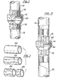
- FIGS. 1 and 2 Examples of assemblies comprising said elements are illustrated in FIGS. 1 and 2. These assemblies consist of a first element or nut 14 intended to tighten the connector, of a second element or part of this idler 16 which can be fixed to the tube 10, and of a third element or fixed part 18 which can be made integral of the tube 12.
- the elements 16 and 18 can be of the female or male type, with planar or conical coupling, and provide for the interposition or not of a lining 20, as is well known in the art. .
- the invention now offers the possibility of producing the parts mentioned above, starting from a tubular steel element of small thickness, but always of thickness greater than approximately 2 mm, which is subjected to deformation operations, in particularly under the effect of mainly axial stresses and under relatively limited forces.
- the invention provides, for most of the connection elements considered, a preliminary phase which consists in stretching a tube 22 (FIG. 3) so as to obtain a tubular element 24 comprising an outer surface of polygonal shape, in particular of octagonal shape or hexagonal with rounded edges, which allows said element to be grasped or tightened with a key of a type known on the market.
- the choice of the external conformation of the tubular element 24 and the choice of the thicknesses of the starting tube 22 are made on the one hand so as to preserve the tubular element 24 of the minimum thicknesses such that they allow subsequent operations to be carried out on this element until the desired connection piece is obtained, which of course has the desired characteristics of resistance to pressure, while on the other hand said choices are influenced also by the consideration that stretching should be carried out in a single pass, and this for reasons of economy, especially because this avoids having to resort to intermediate heat treatment operations.
- the tubular element is cut into sections of tube 26, each according to a prefixed axial dimension, for subsequent operations.
- the method of the invention provides for a local bending deformation towards the inside of the walls of the tube section 26, which is preferably done in at least two phases, as indicated in 28 and 30 in FIG. 4, until the general configuration of the element 14 is obtained, the latter being subsequently machined on its surface 32 (FIG. 4) to produce the internal thread, and, if necessary, on its surface 34 to define the diameter of the corresponding opening.
- the two deformation phases illustrated in FIG. 4 are also shown in FIG.
- the stretched tubular section 26, which has been engaged on a mandrel 36 is brought into contact with a deformation stamp or matrix with a conical configuration 38, then with a plane-shaped matrix 40, which makes it possible to fold the section 26, as shown in 28 and 30, under the ef- £ and of a stress essentially of axial compression exerted on said section.
- the matrix is designed so as to ensure the existence of a zone allowing the material a free expansion, directed radially inwards in the example illustrated, and this in order that the specific stresses cannot increase beyond the limit of deformability of the material. herself .
- the upper and lower surfaces of the element 14 will certainly include nes irregularities in shape, due to an incomplete distribution of the material, in particular the thicker parts after drawing, which are left so as not to exceed in deformation forces, and not to affect the thicknesses.
- FIG. 6 represents the operation which makes it possible to produce the element designated by 16 in FIG. 1, from the section 26 previously stretched.
- This section is first widened in the form of a socket, in its end zone 46, as shown in the figure, then this end zone is completely flattened as indicated by 48, and finally the part is machined to provide it with the thread 50 It is therefore possible to replicate the end zone 46 towards the axis of the part to obtain the part 16 as illustrated in FIG. 2.
- FIG. 7 The operations for passing from tubular section 26 to semi-worked parts 46 and 48 are shown in FIG. 7. It can be seen in this figure that the section 26 is first flared at its end by the action on this end of a die 52, which gives the product half -finished 46, as a result of which this product passes through a planar matrix 54 which makes it possible to form the semi-worked 48. As in the previous case, a mandrel 56 is inserted inside the section 26 and the latter is stressed in the axial direction, the material of the part being left free to expand at least in one zone of the matrix (in this case the expansion being directed towards the outside).
- the die 54 was established with a recess 54 ′ in which the outside edge of the flared end is lodged before closing the die of the semi-worked sleeve 46.
- This flared part is therefore driven back by the matrix 54 and is formed by crushing, so that the reduction in thickness which it had undergone during the previous phase is then compensated and the thickness reduced to the desired value.
- the weak projection 48 ′ (FIG. 6) which will remain in the region of the flanged edge of the part corresponding to the recess 54 ′, can be used to perfect the seal of the lining.
- the third element 18 illustrated in Figures 1 and 2 can be obtained, also starting from the tubular section 26, by means of a series of operations, as shown schematically in Figure 8 with reference to the conical part of the figure 2. These operations include deformation phases to obtain the semi-finished product 58, and machining phases which make it possible to produce the threads 60 ed 62 and to form the lip 72 so as to give the finished part 18 of FIG. 2 .
- the part 18 of fig. 1 is obtained by the same proceeded, but without replying the lip 72.
- the deformation is obtained as illustrated in FIG. 9, in a particular manner in several phases and, in all cases, by mounting the tubular section on a mandrel 64.
- an extender element 66 is introduced which allows slightly increase the diameter of the tubular section 26 within the limits permitted by the material.
- the semi-finished product 68 is subjected to axial deformation, the part being pushed and shaped in contact with the external stamp 70, as illustrated in the middle part of FIG. 9.
- the folded edge 72 is formed (right part of FIG. 9).
- This operation is performed not only by keeping under control the thickness of the material - to compensate for the reduction of the . stricture due to compression, to obtain higher final deformations those which would be allowed by the resistance to the plastic deformation of the material - but also and especially by using a particular technique of compression.
- the axial stress is greater than the elastic limit to the compression of the section of the section, or more precisely, to the buckling load of the individual fibers belonging to the free area of the section, situated along planes passing through the axis of the section, and subject to mutual constraints as we have in the semi-finished product 68. In this way, the free zone of bending 1 of the section can "bulge" towards the outside.
- the thickness involved is defined - within fairly limited limits and, in good substance, independently of the diameter - depending on the machining process, it follows that the length of departure from part 1 of the section 26, which is intended to be deformed to obtain the flared area of the semi-finished product 58 (that is to say the length of the section portion 26 or 62 whose diameter is varied in the matrix 70), also varies within very limited limits, and it has been experimentally observed that to obtain a half-product of type 58, this starting length must have a value around 35 mm and, in any case, less than 45 mm.
- the material is given a possibility of free expansion - with a view to carrying out the deformation under low specific stresses - in particular directed inwards, in the party designated by 74.
- the drawing is preferably carried out by making use of vidia dies having very narrow tolerances, of the order of 0.01 mm per example, while the deformation operations are carried out using a lubricant which is advantageously an anti-seize mixture consisting of oil and sulfur.
- connection elements of the above-specified type in an economically advantageous manner, these elements being able to meet all the specifications of the standardizations. in force at present, and being characterized, with respect to the connections known in the art, essentially by the fact that these elements are made of steel and that they in any case have zero draft angles.
- Another distinguishing characteristic of the connection pieces obtained according to the process of the invention, by comparison with the pieces obtained according to the known technique, is represented by the particular irregularities of their flat outer surfaces, irregularities which have been described in relation to the nut 14 but which are also found in all the other elements considered.
Landscapes
- Engineering & Computer Science (AREA)
- Mechanical Engineering (AREA)
- Shaping Metal By Deep-Drawing, Or The Like (AREA)
- Joints That Cut Off Fluids, And Hose Joints (AREA)
- Joining Of Building Structures In Genera (AREA)
- Mutual Connection Of Rods And Tubes (AREA)
- Lining Or Joining Of Plastics Or The Like (AREA)
- Branch Pipes, Bends, And The Like (AREA)
- Gyroscopes (AREA)
- Lasers (AREA)
Priority Applications (1)
| Application Number | Priority Date | Filing Date | Title |
|---|---|---|---|
| AT81830162T ATE19979T1 (de) | 1980-09-24 | 1981-09-16 | Verfahren zur herstellung eines anschlussnippels. |
Applications Claiming Priority (2)
| Application Number | Priority Date | Filing Date | Title |
|---|---|---|---|
| IT2487880 | 1980-09-24 | ||
| IT24878/80A IT1133613B (it) | 1980-09-24 | 1980-09-24 | Procedimento per lo realizzazione di componenti di raccorderia per tubi,e compnenti cosi' ottenuti |
Publications (2)
| Publication Number | Publication Date |
|---|---|
| EP0048701A1 true EP0048701A1 (de) | 1982-03-31 |
| EP0048701B1 EP0048701B1 (de) | 1986-05-28 |
Family
ID=11215015
Family Applications (1)
| Application Number | Title | Priority Date | Filing Date |
|---|---|---|---|
| EP81830162A Expired EP0048701B1 (de) | 1980-09-24 | 1981-09-16 | Verfahren zur Herstellung eines Anschlussnippels |
Country Status (5)
| Country | Link |
|---|---|
| US (1) | US4452063A (de) |
| EP (1) | EP0048701B1 (de) |
| AT (1) | ATE19979T1 (de) |
| DE (1) | DE3174718D1 (de) |
| IT (1) | IT1133613B (de) |
Cited By (1)
| Publication number | Priority date | Publication date | Assignee | Title |
|---|---|---|---|---|
| WO2025186500A1 (es) * | 2024-03-07 | 2025-09-12 | Enrique Playan Ballarin | Método de fabricación de un accesorio de empalme metálico |
Families Citing this family (16)
| Publication number | Priority date | Publication date | Assignee | Title |
|---|---|---|---|---|
| DE3517163A1 (de) * | 1985-05-11 | 1986-11-13 | Aeroquip GmbH, 7570 Baden-Baden | Verfahren zur herstellung eines schlauchnippels fuer hydraulisch belastete press- oder schraubarmaturen |
| US5165168A (en) * | 1991-04-09 | 1992-11-24 | Higgins Larry B | Method of making a high rise spout and spout made according to the method |
| CA2070857C (fr) * | 1991-07-23 | 2003-12-02 | Michel Gautheron | Procede de formage d'une surepaisseur aux extremites de la douille interne d'une articulation, apres moulage, et ses applications |
| US5341668A (en) * | 1992-12-30 | 1994-08-30 | Corning Incorporated | Method of forming a vessel pouring spout |
| US6808210B1 (en) | 1997-09-03 | 2004-10-26 | The Charles Machine Works, Inc. | Drill pipe with upset ends having constant wall thickness and method for making same |
| USD406639S (en) * | 1998-04-29 | 1999-03-09 | H&H Tube & Manufacturing Co. | Spout design |
| GB2356909B (en) * | 1999-12-01 | 2003-11-12 | Esser Werke Gmbh & Co Kg | Tube for conveying solids |
| US6397652B1 (en) | 2000-03-22 | 2002-06-04 | The Sollami Company | Tool body and method of manufacture |
| CN101817027B (zh) * | 2010-03-30 | 2012-01-25 | 宁波东港紧固件制造有限公司 | 双头管接头冷挤压模具 |
| CN101817028B (zh) * | 2010-03-30 | 2012-12-26 | 宁波市鄞州剑均机械科技有限公司 | 双头管接头的冷挤压模具 |
| US20120256412A1 (en) * | 2011-04-08 | 2012-10-11 | Seung Oh | Joint member manufactured using pipe and manufacturing method of the same |
| DE102012211311A1 (de) * | 2012-06-29 | 2014-01-02 | Behr Gmbh & Co. Kg | Abgaswärmeübertrager |
| US9670951B2 (en) * | 2014-04-08 | 2017-06-06 | A.A.M International S.A.R.L. | Variable-wall light-weight axle shaft with an integral flange member and method for making the same |
| DE102014208093A1 (de) * | 2014-04-29 | 2015-10-29 | Mahle Lnternational Gmbh | Wärmeübertrager |
| US9630451B2 (en) | 2014-06-18 | 2017-04-25 | American Axle & Manufacturing, Inc. | Method of manufacturing hollow axle shaft for a vehicle |
| CN116748458A (zh) * | 2023-05-31 | 2023-09-15 | 四川德兰航宇科技发展有限责任公司 | 一种圆锥型环形锻件底部法兰弯曲成形方法 |
Citations (6)
| Publication number | Priority date | Publication date | Assignee | Title |
|---|---|---|---|---|
| US1408390A (en) * | 1919-02-17 | 1922-02-28 | Nordlund August | Process of forming pipe unions |
| FR567611A (fr) * | 1923-06-19 | 1924-03-07 | Usines De Fabrication De Tubes | Procédé pour munir de collerettes doubles les tubes métalliques et produits en résultant |
| US3109479A (en) * | 1959-06-05 | 1963-11-05 | Penn Aircraft Products Inc | Flaring tool |
| US3266822A (en) * | 1961-08-21 | 1966-08-16 | Price Pfister Brass Mfg | Metal forming process for shaping ends of tubes and the product thereof |
| DE1625981B1 (de) * | 1967-12-18 | 1970-06-25 | Danfoss As | Verfahren zur Herstellung eines Anschlussnippels und einer UEberwurfmutter und zugehoeriges Formstueck |
| FR2379331A1 (fr) * | 1977-02-07 | 1978-09-01 | Gould Inc | Outil a evaser |
Family Cites Families (2)
| Publication number | Priority date | Publication date | Assignee | Title |
|---|---|---|---|---|
| US1142782A (en) * | 1914-12-03 | 1915-06-08 | Rockwood Sprinkler Co | Set of dies. |
| EP0013040A1 (de) * | 1978-12-12 | 1980-07-09 | Polva-Nederland B.V. | Verfahren und Vorrichtung zum Formen von Kunststoff-Kupplungen |
-
1980
- 1980-09-24 IT IT24878/80A patent/IT1133613B/it active
-
1981
- 1981-09-16 EP EP81830162A patent/EP0048701B1/de not_active Expired
- 1981-09-16 AT AT81830162T patent/ATE19979T1/de active
- 1981-09-16 DE DE8181830162T patent/DE3174718D1/de not_active Expired
- 1981-09-22 US US06/304,812 patent/US4452063A/en not_active Expired - Fee Related
Patent Citations (6)
| Publication number | Priority date | Publication date | Assignee | Title |
|---|---|---|---|---|
| US1408390A (en) * | 1919-02-17 | 1922-02-28 | Nordlund August | Process of forming pipe unions |
| FR567611A (fr) * | 1923-06-19 | 1924-03-07 | Usines De Fabrication De Tubes | Procédé pour munir de collerettes doubles les tubes métalliques et produits en résultant |
| US3109479A (en) * | 1959-06-05 | 1963-11-05 | Penn Aircraft Products Inc | Flaring tool |
| US3266822A (en) * | 1961-08-21 | 1966-08-16 | Price Pfister Brass Mfg | Metal forming process for shaping ends of tubes and the product thereof |
| DE1625981B1 (de) * | 1967-12-18 | 1970-06-25 | Danfoss As | Verfahren zur Herstellung eines Anschlussnippels und einer UEberwurfmutter und zugehoeriges Formstueck |
| FR2379331A1 (fr) * | 1977-02-07 | 1978-09-01 | Gould Inc | Outil a evaser |
Cited By (1)
| Publication number | Priority date | Publication date | Assignee | Title |
|---|---|---|---|---|
| WO2025186500A1 (es) * | 2024-03-07 | 2025-09-12 | Enrique Playan Ballarin | Método de fabricación de un accesorio de empalme metálico |
Also Published As
| Publication number | Publication date |
|---|---|
| IT8024878A0 (it) | 1980-09-24 |
| DE3174718D1 (en) | 1986-07-03 |
| IT1133613B (it) | 1986-07-09 |
| ATE19979T1 (de) | 1986-06-15 |
| US4452063A (en) | 1984-06-05 |
| EP0048701B1 (de) | 1986-05-28 |
Similar Documents
| Publication | Publication Date | Title |
|---|---|---|
| EP0048701A1 (de) | Verfahren zur Herstellung eines Anschlussnippels | |
| FR2464424A1 (fr) | Procede pour munir une canalisation d'un embout de raccord et canalisation ainsi obtenue | |
| WO2010046587A1 (fr) | Moyen d'entraînement polygonal à embase incorporée | |
| FR2495508A1 (fr) | Procede pour fabriquer des poulies par roulage a partir d'une feuille metallique et poulies ainsi obtenues | |
| FR3049665A1 (fr) | Piece a sertir sur un support, dispositif comprenant une telle piece et procedes de fabrication d'une telle piece et d'un tel dispositif | |
| FR2760265A1 (fr) | Procede pour ameliorer la resistance a la fatigue due a des mises en pression repetees dans un conduit de derivation pour fluide a haute pression, conduit de derivation obtenu et element avec bague coulissante rapportee | |
| CH631534A5 (fr) | Dispositif de raccordement et procede pour sa fabrication. | |
| FR2498954A1 (fr) | Procede de realisation sans copeaux d'une douille de palier avec partie de fond ou de rebord interieur | |
| EP0013040A1 (de) | Verfahren und Vorrichtung zum Formen von Kunststoff-Kupplungen | |
| EP0014107A1 (de) | Verfahren zur Herstellung einer zylindrischen Büchse mit inneren Nuten, die mindestens an einem ihrer Enden geschlossen sind und hergestellte Büchse | |
| EP0310726B1 (de) | Verfahren zum Herstellen konischer Metalldosen und Werkzeug zur Durchführung des Verfahrens | |
| FR2474908A1 (fr) | Procede et dispositif d'extrusion en chambre fermee pour configurer une tige en metal en une piece en forme de tulipe | |
| FR2544806A1 (fr) | Procede d'assemblage de deux pieces de revolution coaxiales, de meme diametre | |
| EP1473503B1 (de) | Gewellter Schlauch mit zumindest einem metallischen Verstärkungsring und Verfahren zu dessen Herstellung. | |
| CA1284806C (fr) | Joint pour tubes d'acier, son procece de fabrication et outillage pour la mise en oeuvre du procede | |
| WO2014135772A1 (fr) | Outil pour former une collerette a une extremite d'un tube | |
| FR2937568A1 (fr) | Procede de fabrication d'une piece de boulonnerie, outil pour la mise en oeuvre du procede, dispositif de vissage et de devissage d'une telle piece de boulonnerie | |
| FR2498006A1 (fr) | Procede de fabrication de cylindres pour anodes de tubes electroniques | |
| FR2599647A1 (fr) | Procede de fabrication d'un levier de changement de vitesse et levier obtenu | |
| FR2777213A1 (fr) | Procede de fabrication de piece tubulaire metallique et d'arbre tubulaire composite | |
| FR2483809A1 (fr) | Procede et installation pour la fabrication de tubes sur des bancs d'etirage de tubes | |
| FR2604930A1 (fr) | Cylindre de machines a dresser | |
| FR2666179A1 (fr) | Procede pour le montage de la collerette de fixation d'un connecteur a fiches. | |
| CH338299A (fr) | Procédé et appareil pour la fabrication continue d'une pièce tubulaire | |
| FR2652773A1 (fr) | Procede d'obtention d'une douille a collerette, notamment destinee a la liaison d'un tuyau sur un raccord, et dispositif pour sa mise en óoeuvre. |
Legal Events
| Date | Code | Title | Description |
|---|---|---|---|
| PUAI | Public reference made under article 153(3) epc to a published international application that has entered the european phase |
Free format text: ORIGINAL CODE: 0009012 |
|
| AK | Designated contracting states |
Designated state(s): AT BE DE FR GB NL |
|
| 17P | Request for examination filed |
Effective date: 19820924 |
|
| GRAA | (expected) grant |
Free format text: ORIGINAL CODE: 0009210 |
|
| AK | Designated contracting states |
Kind code of ref document: B1 Designated state(s): AT BE DE FR GB NL |
|
| PG25 | Lapsed in a contracting state [announced via postgrant information from national office to epo] |
Ref country code: NL Effective date: 19860528 Ref country code: AT Effective date: 19860528 |
|
| REF | Corresponds to: |
Ref document number: 19979 Country of ref document: AT Date of ref document: 19860615 Kind code of ref document: T |
|
| REF | Corresponds to: |
Ref document number: 3174718 Country of ref document: DE Date of ref document: 19860703 |
|
| PG25 | Lapsed in a contracting state [announced via postgrant information from national office to epo] |
Ref country code: BE Effective date: 19860930 |
|
| NLV1 | Nl: lapsed or annulled due to failure to fulfill the requirements of art. 29p and 29m of the patents act | ||
| BERE | Be: lapsed |
Owner name: SEBASTIANI ENRICO Effective date: 19860930 |
|
| PLBE | No opposition filed within time limit |
Free format text: ORIGINAL CODE: 0009261 |
|
| STAA | Information on the status of an ep patent application or granted ep patent |
Free format text: STATUS: NO OPPOSITION FILED WITHIN TIME LIMIT |
|
| 26N | No opposition filed | ||
| PGFP | Annual fee paid to national office [announced via postgrant information from national office to epo] |
Ref country code: FR Payment date: 19890920 Year of fee payment: 9 |
|
| PGFP | Annual fee paid to national office [announced via postgrant information from national office to epo] |
Ref country code: GB Payment date: 19890930 Year of fee payment: 9 |
|
| PGFP | Annual fee paid to national office [announced via postgrant information from national office to epo] |
Ref country code: DE Payment date: 19891012 Year of fee payment: 9 |
|
| PG25 | Lapsed in a contracting state [announced via postgrant information from national office to epo] |
Ref country code: GB Effective date: 19900916 |
|
| GBPC | Gb: european patent ceased through non-payment of renewal fee | ||
| PG25 | Lapsed in a contracting state [announced via postgrant information from national office to epo] |
Ref country code: FR Effective date: 19910530 |
|
| PG25 | Lapsed in a contracting state [announced via postgrant information from national office to epo] |
Ref country code: DE Effective date: 19910601 |
|
| REG | Reference to a national code |
Ref country code: FR Ref legal event code: ST |