EP0048852A2 - Pupitre de commande de commutateur à pédale - Google Patents
Pupitre de commande de commutateur à pédale Download PDFInfo
- Publication number
- EP0048852A2 EP0048852A2 EP81107133A EP81107133A EP0048852A2 EP 0048852 A2 EP0048852 A2 EP 0048852A2 EP 81107133 A EP81107133 A EP 81107133A EP 81107133 A EP81107133 A EP 81107133A EP 0048852 A2 EP0048852 A2 EP 0048852A2
- Authority
- EP
- European Patent Office
- Prior art keywords
- foot
- foot switch
- control panel
- functions
- switches
- Prior art date
- Legal status (The legal status is an assumption and is not a legal conclusion. Google has not performed a legal analysis and makes no representation as to the accuracy of the status listed.)
- Granted
Links
Images

Classifications
-
- H—ELECTRICITY
- H01—ELECTRIC ELEMENTS
- H01H—ELECTRIC SWITCHES; RELAYS; SELECTORS; EMERGENCY PROTECTIVE DEVICES
- H01H3/00—Mechanisms for operating contacts
- H01H3/02—Operating parts, i.e. for operating driving mechanism by a mechanical force external to the switch
- H01H3/14—Operating parts, i.e. for operating driving mechanism by a mechanical force external to the switch adapted for operation by a part of the human body other than the hand, e.g. by foot
-
- G—PHYSICS
- G05—CONTROLLING; REGULATING
- G05B—CONTROL OR REGULATING SYSTEMS IN GENERAL; FUNCTIONAL ELEMENTS OF SUCH SYSTEMS; MONITORING OR TESTING ARRANGEMENTS FOR SUCH SYSTEMS OR ELEMENTS
- G05B19/00—Program-control systems
- G05B19/02—Program-control systems electric
- G05B19/04—Program control other than numerical control, i.e. in sequence controllers or logic controllers
- G05B19/10—Program control other than numerical control, i.e. in sequence controllers or logic controllers using selector switches
- G05B19/106—Program control other than numerical control, i.e. in sequence controllers or logic controllers using selector switches for selecting a program, variable or parameter
-
- H—ELECTRICITY
- H01—ELECTRIC ELEMENTS
- H01H—ELECTRIC SWITCHES; RELAYS; SELECTORS; EMERGENCY PROTECTIVE DEVICES
- H01H2217/00—Facilitation of operation; Human engineering
- H01H2217/04—Mimics of controlled apparatus or symbol
-
- H—ELECTRICITY
- H01—ELECTRIC ELEMENTS
- H01H—ELECTRIC SWITCHES; RELAYS; SELECTORS; EMERGENCY PROTECTIVE DEVICES
- H01H2239/00—Miscellaneous
- H01H2239/05—Mode selector switch, e.g. shift, or indicator
-
- H—ELECTRICITY
- H01—ELECTRIC ELEMENTS
- H01H—ELECTRIC SWITCHES; RELAYS; SELECTORS; EMERGENCY PROTECTIVE DEVICES
- H01H2300/00—Orthogonal indexing scheme relating to electric switches, relays, selectors or emergency protective devices covered by H01H
- H01H2300/014—Application surgical instrument
Definitions
- the invention relates to a foot control panel, preferably for surgical microscopes, with one or more foot switches for actuating numerous functions.
- the surgeon cannot avoid changing certain settings of the microscope during a microsurgical intervention. This affects e.g. the height adjustment of the microscope, its focus, the magnification of the microscope or the illuminance of the operating field. Additional devices are also possible, e.g. the swiveling slit lamp used in ophthalmology, and finally other devices, such as To operate drills, engine trepan, glow cautery or even photo and film equipment.
- the settings mentioned and the commissioning of the devices are preferably carried out with foot switches, since the surgeon e.g. holds the suction device with one hand and has to guide a microsurgical instrument such as tweezers with the other hand.
- a microsurgical instrument such as tweezers with the other hand.
- the space requirement increases with each additional switch.
- known footswitches for 12 functions for example, have the disadvantage that only a maximum of 12 functions can be switched; for spatial reasons, they cannot generally be expanded if further functions are required.
- the invention is therefore an object of the invention to provide a foot control panel that allows quick and safe operation of numerous functions with one or a few foot switches.
- the object is achieved by a switching device with which the functions of the foot switch or . the foot switch can be selected.
- a foot switch preferably a rocker switch
- a control panel is provided with a number of selection buttons, which have obvious short names such as focus, lamp or the like. By calling the surgeon, the instrument nurse selects it so that when the foot switch is actuated the function concerned is changed.
- electronics can be used to operate any desired number of functions with a single foot switch.
- the foot control panel therefore has two foot switches, in which the rocker switch for the Y-axis is arranged rotated by 90 ° with respect to the other rocker switch in the interest of a sensible actuation.
- This embodiment is also suitable for other applications in which it is often necessary to switch between two functions.
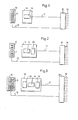
- Fig. 1 denotes the foot switch, which in this embodiment contains only one foot switch 14.
- the foot switch 14 is preferably designed as a rocker switch; in this case, the pressure on its left and right side causes two different functions or an adjustment movement in two different directions.
- the foot switch 13 is connected via the multi-core cable 17 to the switching unit 18, which in turn is connected to the control panel 10 via the multi-core cable 12. (The switching unit can also be part of the control panel.)
- the control panel 10 contains a number of selection buttons 11, which meaningful due short names such as focus, lamp or the like.
- the foot switch 14 When they are actuated, the foot switch 14 is switched to the corresponding lines 19 via the switching unit 18, so that when it is operated the function provided by the selection keys 11 is carried out, the selection keys 11 are preferably designed as illuminated pushbuttons so that one can immediately recognize which ones on the control panel 10 Function is switched on. Double actuation of the selection buttons can be prevented mechanically or electronically in a known manner.
- Fig. 2 shows an embodiment in which the foot switch includes two foot switches 14 and 25, e.g. perform the adjustment of a microscope in two mutually perpendicular axes. In this case, no operation on the control panel 10 is necessary when changing the adjustment axis. This is always an advantage if you frequently have to switch between two functions. In this version, the surgeon can also choose whether the other functions should be performed with the horizontal or vertical foot switch.
- FIG. 3 A further exemplary embodiment is shown in FIG. 3.
- a third foot switch 36 is used to additionally actuate the switchover unit, so that the operator is no longer dependent on the help of a nurse.
- the previous function is assigned to the other foot switch (s); when printing on the lower part the following.
- the illuminated selection keys 11 on the control unit 10 indicate which function is switched on or which functions are switched on.
- the switchover unit can also be operated via a known speech analyzer that responds to spoken command words whose clan spectra are in it stores are.
- FIG. 4 A possible circuit for the embodiment shown in FIG. 2 is shown in FIG. 4.
- 44a, 44e, etc. denote electronic memories which consist, for example, of flip-flops.
- the memory associated with it is set by a known electronic circuit 42 and all other memories are reset.
- the known circuit 42 also prevents double actuation.
- the memory 44a is set via the line 43a and voltage is supplied via the line 45a to the AND gates 47a and 47b, while there is no voltage to the AND gates 47e, 47f etc.
- the lamp 46a receives voltage; its glow shows that (last) the -'I'la key was pressed.
- Fig. 4 also shows an example of the operation of two foot switches for related functions.
- the AND gates 47c and 47d also receive voltage, so that when the foot switch 23 is actuated, a further function can be triggered via 49c and 49d, e.g. the movement in two directions on another axis.
Landscapes
- Physics & Mathematics (AREA)
- General Physics & Mathematics (AREA)
- Engineering & Computer Science (AREA)
- Automation & Control Theory (AREA)
- Microscoopes, Condenser (AREA)
- Surgical Instruments (AREA)
- Accommodation For Nursing Or Treatment Tables (AREA)
- Keying Circuit Devices (AREA)
Applications Claiming Priority (2)
| Application Number | Priority Date | Filing Date | Title |
|---|---|---|---|
| DE3036798 | 1980-09-30 | ||
| DE19803036798 DE3036798A1 (de) | 1980-09-30 | 1980-09-30 | Fussschaltpult |
Publications (4)
| Publication Number | Publication Date |
|---|---|
| EP0048852A2 true EP0048852A2 (fr) | 1982-04-07 |
| EP0048852A3 EP0048852A3 (en) | 1982-12-29 |
| EP0048852B1 EP0048852B1 (fr) | 1985-08-07 |
| EP0048852B2 EP0048852B2 (fr) | 1990-08-08 |
Family
ID=6113177
Family Applications (1)
| Application Number | Title | Priority Date | Filing Date |
|---|---|---|---|
| EP81107133A Expired - Lifetime EP0048852B2 (fr) | 1980-09-30 | 1981-09-10 | Pupitre de commande de commutateur à pédale |
Country Status (4)
| Country | Link |
|---|---|
| EP (1) | EP0048852B2 (fr) |
| JP (1) | JPS5788627A (fr) |
| BR (1) | BR8105943A (fr) |
| DE (2) | DE3036798A1 (fr) |
Cited By (1)
| Publication number | Priority date | Publication date | Assignee | Title |
|---|---|---|---|---|
| EP1376187A1 (fr) * | 2002-06-14 | 2004-01-02 | Leica Microsystems (Schweiz) AG | Commande vocale pour microscopes chirurgicaux |
Family Cites Families (6)
| Publication number | Priority date | Publication date | Assignee | Title |
|---|---|---|---|---|
| US2482550A (en) * | 1947-05-24 | 1949-09-20 | Furnas Electric Co | Foot actuated rotary switch |
| US3688126A (en) * | 1971-01-29 | 1972-08-29 | Paul R Klein | Sound-operated, yes-no responsive switch |
| DE2530108C3 (de) * | 1975-07-05 | 1980-07-10 | Emda Fabrik Elektro-Medizinischer Und Dentaler Apparate Georg Hartmann Gmbh & Co Kg, 6000 Frankfurt | Steuervorrichtung für zahnärztliche Behandlungsgeräte mit einer Fußschalteranordnung |
| US4045630A (en) * | 1975-09-08 | 1977-08-30 | The United States Of America As Represented By The Secretary Of The Department Of Health, Education And Welfare | Chin activated switch |
| DE2842622C2 (de) * | 1978-09-29 | 1984-10-25 | Siemens AG, 1000 Berlin und 8000 München | Bedienungspult |
| JPS5597924U (fr) * | 1978-12-28 | 1980-07-08 |
-
1980
- 1980-09-30 DE DE19803036798 patent/DE3036798A1/de not_active Withdrawn
-
1981
- 1981-09-10 DE DE8181107133T patent/DE3171706D1/de not_active Expired
- 1981-09-10 EP EP81107133A patent/EP0048852B2/fr not_active Expired - Lifetime
- 1981-09-17 BR BR8105943A patent/BR8105943A/pt unknown
- 1981-09-30 JP JP56154045A patent/JPS5788627A/ja active Pending
Cited By (1)
| Publication number | Priority date | Publication date | Assignee | Title |
|---|---|---|---|---|
| EP1376187A1 (fr) * | 2002-06-14 | 2004-01-02 | Leica Microsystems (Schweiz) AG | Commande vocale pour microscopes chirurgicaux |
Also Published As
| Publication number | Publication date |
|---|---|
| DE3171706D1 (en) | 1985-09-12 |
| BR8105943A (pt) | 1982-06-08 |
| JPS5788627A (en) | 1982-06-02 |
| EP0048852A3 (en) | 1982-12-29 |
| DE3036798A1 (de) | 1982-05-13 |
| EP0048852B1 (fr) | 1985-08-07 |
| EP0048852B2 (fr) | 1990-08-08 |
Similar Documents
| Publication | Publication Date | Title |
|---|---|---|
| EP0819409B1 (fr) | Générateur électrochirurgical et son procédé de fonctionnement | |
| EP0521261A1 (fr) | Instrument médical avec interrupteur pour commander des appareils externes | |
| EP1785122A1 (fr) | Dispositif pour régler la surface de couchage d'une table d'opération | |
| DE3607945A1 (de) | Bedienungspult fuer drucker, insbesondere fuer matrixdrucker | |
| DE3304041C2 (fr) | ||
| DE2430263A1 (de) | Schlitzlampe mit kombinierter schlitzund lampenintensitaetseinstellvorrichtung | |
| DE3124354C2 (de) | Locher für blatt- und folienförmiges Material | |
| EP0608771A1 (fr) | Dispositif et méthode d'actionnement de composants intégrés dans un véhicule automobile | |
| DE3330116A1 (de) | Roentgendiagnostikgenerator | |
| EP0048852B1 (fr) | Pupitre de commande de commutateur à pédale | |
| EP2702472A1 (fr) | Élément de commande pour installation d'éclairage | |
| WO2002082954A1 (fr) | Mecanisme de commande a moteur electrique pour mobilier, utilise pour deplacer les parties d'un meubles les unes par rapport aux autres | |
| DE2523887C3 (de) | Röntgendiagnostikanlage mit mehreren röntgenologischen Aufnahmesystemen | |
| DE19957919A1 (de) | Schaltvorrichtung für elektrochirurgische Geräte | |
| DE102013108228A1 (de) | Assistenzeinrichtung zur bildgebenden Unterstützung eines Operateurs während eines chirurgischen Eingriffs | |
| DE3741735A1 (de) | Anzeigevorrichtung | |
| DE102004034848B4 (de) | Inverses Mikroskop | |
| DE7237912U (de) | Vorrichtung zur steuerung von mikrochirurgischen geraeten | |
| DE2850230A1 (de) | Schaltgeraet fuer zahntechnische elektromotoren | |
| DE2556042C3 (de) | Einrichtung zur Steuerung mehrerer, voneinander unabhängiger Stellgrößen | |
| DE969897C (de) | Aufnahmewahlschalter fuer einen Roentgendiagnostikapparat | |
| DE102005013152A1 (de) | Automatisiertes Mikroskop | |
| DE1939009C (de) | Schaltungsanordnung für Fernmeldeanlagen, insbesondere Fernsprechvermittlungsanlagen, in welchen individuelle Schalteinrichtungen an zentrale Schalteinrichtungen einzeln angeschaltet werden | |
| DE2258866C2 (de) | Röntgenzielgerät mit einem Tastschalter zum Einschalten der Durchleuchtungsspannung | |
| EP2017864B1 (fr) | Dispositif de commutation |
Legal Events
| Date | Code | Title | Description |
|---|---|---|---|
| PUAI | Public reference made under article 153(3) epc to a published international application that has entered the european phase |
Free format text: ORIGINAL CODE: 0009012 |
|
| AK | Designated contracting states |
Designated state(s): CH DE FR GB |
|
| PUAL | Search report despatched |
Free format text: ORIGINAL CODE: 0009013 |
|
| AK | Designated contracting states |
Designated state(s): CH DE FR GB LI |
|
| RHK1 | Main classification (correction) |
Ipc: H01H 3/14 |
|
| 17P | Request for examination filed |
Effective date: 19830407 |
|
| GRAA | (expected) grant |
Free format text: ORIGINAL CODE: 0009210 |
|
| AK | Designated contracting states |
Designated state(s): CH DE FR GB LI |
|
| REF | Corresponds to: |
Ref document number: 3171706 Country of ref document: DE Date of ref document: 19850912 |
|
| ET | Fr: translation filed | ||
| PLBI | Opposition filed |
Free format text: ORIGINAL CODE: 0009260 |
|
| 26 | Opposition filed |
Opponent name: SIEMENS AKTIENGESELLSCHAFT, BERLIN UND MUENCHEN Effective date: 19860502 |
|
| GBPC | Gb: european patent ceased through non-payment of renewal fee | ||
| PG25 | Lapsed in a contracting state [announced via postgrant information from national office to epo] |
Ref country code: GB Effective date: 19881118 |
|
| PG25 | Lapsed in a contracting state [announced via postgrant information from national office to epo] |
Ref country code: LI Effective date: 19890930 Ref country code: CH Effective date: 19890930 |
|
| PG25 | Lapsed in a contracting state [announced via postgrant information from national office to epo] |
Ref country code: FR Effective date: 19900531 |
|
| REG | Reference to a national code |
Ref country code: CH Ref legal event code: PL |
|
| PG25 | Lapsed in a contracting state [announced via postgrant information from national office to epo] |
Ref country code: DE Effective date: 19900601 |
|
| PUAH | Patent maintained in amended form |
Free format text: ORIGINAL CODE: 0009272 |
|
| STAA | Information on the status of an ep patent application or granted ep patent |
Free format text: STATUS: PATENT MAINTAINED AS AMENDED |
|
| REG | Reference to a national code |
Ref country code: FR Ref legal event code: ST |
|
| 27A | Patent maintained in amended form |
Effective date: 19900808 |
|
| AK | Designated contracting states |
Kind code of ref document: B2 Designated state(s): CH DE FR GB LI |
|
| EN3 | Fr: translation not filed ** decision concerning opposition |