EP0048872A1 - Dispositif pour la croissance épitaxiale en phase liquide - Google Patents
Dispositif pour la croissance épitaxiale en phase liquide Download PDFInfo
- Publication number
- EP0048872A1 EP0048872A1 EP81107190A EP81107190A EP0048872A1 EP 0048872 A1 EP0048872 A1 EP 0048872A1 EP 81107190 A EP81107190 A EP 81107190A EP 81107190 A EP81107190 A EP 81107190A EP 0048872 A1 EP0048872 A1 EP 0048872A1
- Authority
- EP
- European Patent Office
- Prior art keywords
- substrate
- chambers
- slide
- tongues
- crucibles
- Prior art date
- Legal status (The legal status is an assumption and is not a legal conclusion. Google has not performed a legal analysis and makes no representation as to the accuracy of the status listed.)
- Granted
Links
- 238000004943 liquid phase epitaxy Methods 0.000 title claims description 5
- 239000000758 substrate Substances 0.000 claims abstract description 75
- 210000002105 tongue Anatomy 0.000 claims abstract description 68
- 238000000151 deposition Methods 0.000 claims abstract description 42
- 235000012431 wafers Nutrition 0.000 claims abstract description 40
- 230000008021 deposition Effects 0.000 claims description 40
- 238000000926 separation method Methods 0.000 claims description 30
- 238000002844 melting Methods 0.000 claims description 13
- 230000008018 melting Effects 0.000 claims description 13
- 238000006073 displacement reaction Methods 0.000 claims description 9
- 239000004065 semiconductor Substances 0.000 claims description 4
- 230000005484 gravity Effects 0.000 claims description 3
- 238000004519 manufacturing process Methods 0.000 claims description 3
- 238000003825 pressing Methods 0.000 claims description 3
- 239000000155 melt Substances 0.000 description 17
- 239000000463 material Substances 0.000 description 2
- UFHFLCQGNIYNRP-UHFFFAOYSA-N Hydrogen Chemical compound [H][H] UFHFLCQGNIYNRP-UHFFFAOYSA-N 0.000 description 1
- 238000010276 construction Methods 0.000 description 1
- 239000013078 crystal Substances 0.000 description 1
- 230000003247 decreasing effect Effects 0.000 description 1
- 238000011161 development Methods 0.000 description 1
- 230000018109 developmental process Effects 0.000 description 1
- 230000000694 effects Effects 0.000 description 1
- 238000000407 epitaxy Methods 0.000 description 1
- 239000007789 gas Substances 0.000 description 1
- 238000000265 homogenisation Methods 0.000 description 1
- 239000001257 hydrogen Substances 0.000 description 1
- 229910052739 hydrogen Inorganic materials 0.000 description 1
- 238000002347 injection Methods 0.000 description 1
- 239000007924 injection Substances 0.000 description 1
- 238000000034 method Methods 0.000 description 1
- 239000000203 mixture Substances 0.000 description 1
- 230000000704 physical effect Effects 0.000 description 1
- 239000010453 quartz Substances 0.000 description 1
- 238000007789 sealing Methods 0.000 description 1
- VYPSYNLAJGMNEJ-UHFFFAOYSA-N silicon dioxide Inorganic materials O=[Si]=O VYPSYNLAJGMNEJ-UHFFFAOYSA-N 0.000 description 1
- 239000007787 solid Substances 0.000 description 1
Images


Classifications
-
- C—CHEMISTRY; METALLURGY
- C30—CRYSTAL GROWTH
- C30B—SINGLE-CRYSTAL GROWTH; UNIDIRECTIONAL SOLIDIFICATION OF EUTECTIC MATERIAL OR UNIDIRECTIONAL DEMIXING OF EUTECTOID MATERIAL; REFINING BY ZONE-MELTING OF MATERIAL; PRODUCTION OF A HOMOGENEOUS POLYCRYSTALLINE MATERIAL WITH DEFINED STRUCTURE; SINGLE CRYSTALS OR HOMOGENEOUS POLYCRYSTALLINE MATERIAL WITH DEFINED STRUCTURE; AFTER-TREATMENT OF SINGLE CRYSTALS OR A HOMOGENEOUS POLYCRYSTALLINE MATERIAL WITH DEFINED STRUCTURE; APPARATUS THEREFOR
- C30B19/00—Liquid-phase epitaxial-layer growth
- C30B19/06—Reaction chambers; Boats for supporting the melt; Substrate holders
- C30B19/063—Sliding boat system
Definitions
- the present invention relates to a device as specified in the preamble of claim 1.
- a device for carrying out a liquid phase epitaxy for the production of semiconductor layers on a plurality of substrate wafers at the same time which has the features of the preamble of claim 1, is used by Bell Laboratories. It is a device in which a crucible is present. From the side through this crucible plates are inserted as slidable tongues, each having a hole. If this bore is in the crucible, it fills with an amount of the melt which corresponds to the volume of the bore and is referred to as an aliquot. The tongue is then shifted in such a way that this hole is pushed out of the crucible and passes over a substrate disk provided.
- a semiconductor layer is deposited on the surface of the substrate wafer from the melt contained in the bore and now located above the substrate wafer according to the principle of liquid phase epitaxy.
- DE-OS 27 30 358 It is known from DE-OS 27 30 358 (YPA 77 P 7080) to provide a plurality of substrate wafers with a plurality of epitaxial layers on top of one another in a successive sequence.
- This device consists of a multiplicity of melting crucibles and a displaceable tongue with a multiplicity of recesses corresponding to the number of the substrate disks for receiving the substrate disks. If several layers are deposited on different substrate wafers at the same time, the nth layer is deposited on the mth substrate wafer at a different time, and therefore at different temperature conditions than the nth layer on the (m + m ' ) -th substrate disk.
- the part with the separation chambers 3 is designated.
- the part with the crucibles 5 is designated.
- the parts 2 and 4 are slidably sliding against each other.
- the contact surface between these two parts 2 and 4 is designated 6.
- a lid lying on the part 4 and closing the melting chambers 5 is designated by 7.
- the slide tongues 8 are partially in the slots of part 2 with the separation chambers 3.
- the slide tongues 8 protrude at least on the left in FIGS .
- the summarizing housing is designated with which the part 2 with the separation chambers 3, the slide tongues 8 and the part 4 with the melting chambers 5 are held together.
- this housing can consist of two parts screwed together, the part 4 (with the melting chambers 5) and the cover 7 being further parts of this housing.
- the housing 10 can be addressed as fixed, in which the part 2 and the slide tongues 8 (both separately) can be moved.
- part 1 shows the view of the device 1 according to the invention in the operating state which is present before the melt is transferred from the crucible 5 into the deposition chambers 3.
- part 2 is shifted in the direction of arrow 11 in such a way that the separation chambers 3 get under the crucible 5.
- part 2 is displaceable relative to part 4, which is firmly connected to housing 10.
- part 4 could also ver slidable and part 2 fixed.
- the distances between the separation chambers 3 from one another and the distances between the crucibles 5 from one another are the same. large to choose and so large that in the initial position shown in Fig.1, the crucible 5 and the separation chambers 3 are closed against each other and overlap sufficiently in the moved state.
- the slide tongues 8 have recesses 12 for receiving one substrate wafer each.
- a further receptacle 13 (shown in dashed lines) is provided in each slide tongue 8.
- the substrate disk 14 to be coated is located in the receptacle 12.
- the pre-substrate disk of the same size, which is to be inserted into the receptacle 13, is not shown here for the sake of clarity.
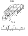
- FIG. 4 shows a detailed illustration of part 2 with the deposition chambers 3 and three slide tongues 8, 8 ', in which only the recesses 12 for the substrate wafer to be coated are shown.
- these recesses 12 are provided opposite one another on both sides in the slide tongues, so that with two slide tongues 8,8 'four substrate disks can already be accommodated in the four recesses 12.
- the slide tongues 8 are perpendicular to the support surface 7, so that the substrate disks inserted into the recesses 12 are passed through the deposition chambers 3 in a vertical position when displaced in the direction of the arrow 9.
- the dimensions 8 and those of the recesses 12 (and the substrate wafers) are all the greater than the corresponding dimensions Dimension a 'and b' of the deposition chambers 3 such that the lower edge of the substrate disk inserted into the recess 12 is constantly below the floor 3 * the separating chamber 3 is sufficient and when pushed in the direction 9 either the front edge 12 'or the rear edge 12 "is still or already in the solid part of part 2, ie outside the separating chamber 3.
- the substrate disc located in the respective receptacle 12 becomes thereby always securely held in the receptacle 12.
- the distances between adjacent slide tongues are very small compared to the length dimensions a 'and b', so that the total surface of this volume portion of the deposition chamber 3 filled with melt is between the adjacent slide tongues essentially from the surface of the two substrate disks (which are opposite one another with respect to this volume fraction) in the out Takes 12 of the two slide tongues is taken. This contributes significantly to the homogeneity of the deposition on the substrate wafers, in particular without substantial (reinforced) edge growth, as has been known and feared for many years by the sliding epitaxy. In the case of a plurality of slide tongues as shown in FIG.
- this essential advantage can be achieved for the substrate disks of all slide tongues if recesses (and substrate disks) are omitted in the two outer slide tongues on their respective outer sides. There is then no separation from the two volume fractions of each separation chamber 3, which are located between the respective outer slide tongue 8 'and the respective outer walls of the separation chamber 3 which are parallel to the slide tongues 8'.
- the part 2 with the separation chambers 3 consists of a number of individual plates which are alternately assembled with the slide tongues 8,8 '(see Fig. 3).
- 5 shows, designated 22, such a plate as it is arranged between the slide tongues 8.
- Reference number 3 indicates the four separation chambers.
- the first separation chamber 3 is formed by the entirety of the recesses 33 ′ of the individual plates 22.
- the recesses 33 "of the plates 22 form the next separation chamber 3.
- All plates 22 of part 2 are advantageously identical parts, since the two can be seen in FIG Parts of the housing 10 which can form the aforementioned, the sliding tongues 8 parallel outer wall of the separation chamber 3.
- the surface 10 'of the housing 10 is taken together by the lower edge surfaces 10 "of the plates 22 and the lower edge surfaces 10"' of the slide tongues 8 (see FIG. 4), so that the dimension A entered in FIG. 5 corresponds to that in FIG. 4.
- the entered dimension A corresponds.
- the individual plates each have a recess 122 for receiving a locking pin 123.
- the slide tongues also have such a recess.
- the pin 123 shown in Fig. 2 not only locks the plates 22 against each other, but also the slide tongues 8, 8 'with the plates 22, i.e. with part 2.
- FIG. 1 and 2 show the operating state of the device according to the invention as it is before the melt is poured from the crucibles 5 into the deposition chambers 3.
- the slide tongues 8, 8 ' are already in the part 2 and thus divide out how 4 shows the individual separation chambers 3 in the partial volumes between the slide tongues 8, 8 '.
- These partial volumes are also referred to as aliquots, because when the melt is poured into the melting chambers, these partial volumes are the individual portions of the melt from which the individual epitaxial layer is later deposited on the respective substrate wafer.
- each aliquot becomes two substrate slices located in the recesses 12 ben coated.
- the melting chambers 3 are already divided into the partial volumes mentioned from the outset.
- melt 51 can reach the individual partial volumes of the deposition chamber 3 in this state. Since the melt 51 is very viscous, the force of gravity is generally not sufficient to ensure that the melt 51 reliably and evenly fills the partial volumes of the deposition chamber 3. Pressure must be applied.
- the part 4 with the crucibles 5 is formed in two parts and consists of the two comb-like intermeshing parts 41 and 42. On each side between the intermeshing comb teeth of the parts 41 and 42 there are the crucibles 5. By moving the parts 41 and 42 against each other, as shown in Fig.1. and 2 can be seen, volumes of the crucible 5 are reduced.
- this movement of the parts 41 and 42 of the part 4 takes place against one another in that only the part 41 is fixedly mounted in the holder 10 and the part 42 (like the part 2) is displaceable relative to the housing 10 .
- This displacement is achieved in a simple manner in this embodiment in that the abovementioned contact surface 132 is located on part 42.
- the part 42 is taken and moved against the fixed part 41. The result of this displacement of the part 42 is - as can be clearly seen from FIG.
- 6b shows an already relatively advanced stage in which almost the entire melt 51 has already been pressed into the partial volumes of the deposition chamber 3 located between the slide tongues 8, 8 '.
- Precautions have been taken, for example narrow channels seen through which gas contained in the separating chambers 3 can escape when the respective melt is pressed in.
- Fig. 6c finally shows the final state in which the respective volume of the individual melting chambers has become zero, i.e. the respective surfaces 142 and 141 already lie against one another. The entire melt of the respective crucible 5 is now in the associated deposition chamber 3.
- the deposition to be carried out later on the substrate wafers is then based on aliquots which are identical to one another.
- the locking pin 123 falls out of the recesses 122 and then passes into the recess 124 of the housing 10, which is below the recesses 122.
- the slide tongues 8, 8 ' relative to part 2 or relative to the plates 22 of part 2 further displaceable. This further displacement of the slide tongues 8, 8 'in the direction of the arrow 9 allows the substrate disks located in all the recesses 12 of all slide tongues 8, 8' to get into the (from the left) first deposition chamber 3.
- this pre-substrate 13 firstly reaches the first deposition chamber 3. This pre-substrate then serves to eliminate any supersaturation that may be present in the aliquots by deposition on these pre-substrate wafers. The actual intended deposition then takes place after — as already described above — the substrate disks of the recesses 12 are pushed into the deposition chambers 3.
- the substrate disks of the recesses 12 of the slide tongues 8, 8 ' are successively pushed from a deposition chamber into the deposition chamber next in the direction of arrow 9 and then coated with the further epitaxial layer. After the substrate wafers of the recesses 12 have passed through all four deposition chambers 3, these substrate wafers have the desired four epitaxial layers lying one above the other. The substrate wafers are then removed from the device according to the invention.
- this device 1 shows the device according to the invention in such a position that, with respect to gravity, the melting crucibles 5 are above the deposition chambers 3 and the substrate disks are located in the recesses 12 in a vertical position in the deposition chambers 3.
- this device 1 is arranged in a quartz tube 100 which is located in a corresponding furnace.
- 101 is a supply pipe for hydrogen and 102 is a pipe for a thermocouple.
- the arrangement according to the invention can also be used in a position in which the slide tongues 8 lie horizontally and the recesses are located in the respective upper surfaces of the slide tongues 8.
Landscapes
- Chemical & Material Sciences (AREA)
- Engineering & Computer Science (AREA)
- Crystallography & Structural Chemistry (AREA)
- Materials Engineering (AREA)
- Metallurgy (AREA)
- Organic Chemistry (AREA)
- Liquid Deposition Of Substances Of Which Semiconductor Devices Are Composed (AREA)
- Crystals, And After-Treatments Of Crystals (AREA)
Applications Claiming Priority (2)
| Application Number | Priority Date | Filing Date | Title |
|---|---|---|---|
| DE3036643A DE3036643C2 (de) | 1980-09-29 | 1980-09-29 | Vorrichtung zur Flüssigphasen-Epitaxie |
| DE3036643 | 1980-09-29 |
Publications (2)
| Publication Number | Publication Date |
|---|---|
| EP0048872A1 true EP0048872A1 (fr) | 1982-04-07 |
| EP0048872B1 EP0048872B1 (fr) | 1985-08-07 |
Family
ID=6113095
Family Applications (1)
| Application Number | Title | Priority Date | Filing Date |
|---|---|---|---|
| EP81107190A Expired EP0048872B1 (fr) | 1980-09-29 | 1981-09-11 | Dispositif pour la croissance épitaxiale en phase liquide |
Country Status (5)
| Country | Link |
|---|---|
| US (1) | US4406245A (fr) |
| EP (1) | EP0048872B1 (fr) |
| JP (1) | JPS5788093A (fr) |
| CA (1) | CA1167573A (fr) |
| DE (1) | DE3036643C2 (fr) |
Families Citing this family (6)
| Publication number | Priority date | Publication date | Assignee | Title |
|---|---|---|---|---|
| US4519871A (en) * | 1983-11-25 | 1985-05-28 | Cook Melvin S | Bubble-mode liquid phase epitaxy |
| US4774904A (en) * | 1986-09-29 | 1988-10-04 | Jamie Knapp | Multiple-layer growth of plural semiconductor devices |
| JPS6436017U (fr) * | 1987-08-27 | 1989-03-06 | ||
| US7905197B2 (en) * | 2008-10-28 | 2011-03-15 | Athenaeum, Llc | Apparatus for making epitaxial film |
| US8193078B2 (en) | 2008-10-28 | 2012-06-05 | Athenaeum, Llc | Method of integrating epitaxial film onto assembly substrate |
| US20100102419A1 (en) * | 2008-10-28 | 2010-04-29 | Eric Ting-Shan Pan | Epitaxy-Level Packaging (ELP) System |
Citations (3)
| Publication number | Priority date | Publication date | Assignee | Title |
|---|---|---|---|---|
| US3759759A (en) * | 1970-01-29 | 1973-09-18 | Fairchild Camera Instr Co | Push pull method for solution epitaxial growth of iii v compounds |
| USRE28140E (en) * | 1971-11-29 | 1974-08-27 | Bergh ctal | |
| FR2439477A1 (fr) * | 1978-10-20 | 1980-05-16 | Matsushita Electric Industrial Co Ltd | Procede et dispositif de fabrication de semi-conducteurs par croissance epitaxiale en phase liquide |
Family Cites Families (8)
| Publication number | Priority date | Publication date | Assignee | Title |
|---|---|---|---|---|
| FR1600341A (fr) * | 1968-12-31 | 1970-07-20 | ||
| US3990392A (en) * | 1968-12-31 | 1976-11-09 | U.S. Philips Corporation | Epitaxial growth apparatus |
| JPS5213510B2 (fr) * | 1973-02-26 | 1977-04-14 | ||
| US3853643A (en) * | 1973-06-18 | 1974-12-10 | Bell Telephone Labor Inc | Epitaxial growth of group iii-v semiconductors from solution |
| DE2337238A1 (de) * | 1973-07-21 | 1975-01-30 | Licentia Gmbh | Verfahren und vorrichtung zur epitaktischen ablagerung kristallisierter schichten auf einem einkristallinen substrat aus einem material in fluessigem zustand |
| DD115580A1 (fr) * | 1974-10-15 | 1975-10-12 | ||
| DE2730358C3 (de) * | 1977-07-05 | 1982-03-18 | Siemens AG, 1000 Berlin und 8000 München | Verfahren zum aufeinanderfolgenden Abscheiden einkristalliner Schichten auf einem Substrat nach der Flüssigphasen-Schiebeepitaxie |
| US4214550A (en) * | 1979-05-21 | 1980-07-29 | Rca Corporation | Apparatus for the deposition of a material from a liquid phase |
-
1980
- 1980-09-29 DE DE3036643A patent/DE3036643C2/de not_active Expired
-
1981
- 1981-09-02 US US06/298,594 patent/US4406245A/en not_active Expired - Fee Related
- 1981-09-11 EP EP81107190A patent/EP0048872B1/fr not_active Expired
- 1981-09-28 JP JP56153532A patent/JPS5788093A/ja active Granted
- 1981-09-28 CA CA000386793A patent/CA1167573A/fr not_active Expired
Patent Citations (3)
| Publication number | Priority date | Publication date | Assignee | Title |
|---|---|---|---|---|
| US3759759A (en) * | 1970-01-29 | 1973-09-18 | Fairchild Camera Instr Co | Push pull method for solution epitaxial growth of iii v compounds |
| USRE28140E (en) * | 1971-11-29 | 1974-08-27 | Bergh ctal | |
| FR2439477A1 (fr) * | 1978-10-20 | 1980-05-16 | Matsushita Electric Industrial Co Ltd | Procede et dispositif de fabrication de semi-conducteurs par croissance epitaxiale en phase liquide |
Non-Patent Citations (2)
| Title |
|---|
| IEEE Transactions on Electron Devices, Vol. ED-24, No. 7, 1977 T. NIINA et al. "An Improved Liquid Phase Epitaxial Growth Method for Mass Production of GaP Green Led's", seiten 946-950. * seite 947; figur 1 * * |
| Instruments and Experimental Techniques, Vol. 19, No. 4, pt. 2, 1976 S.G. ZHILENIS et al. "Cassette for Batch Growth of Layers by the Liquid-Epitaxy Method", seiten 1221-1222. * seite 1222, figur 1 * * |
Also Published As
| Publication number | Publication date |
|---|---|
| CA1167573A (fr) | 1984-05-15 |
| DE3036643A1 (de) | 1982-04-08 |
| JPS614797B2 (fr) | 1986-02-13 |
| EP0048872B1 (fr) | 1985-08-07 |
| DE3036643C2 (de) | 1984-09-20 |
| US4406245A (en) | 1983-09-27 |
| JPS5788093A (en) | 1982-06-01 |
Similar Documents
| Publication | Publication Date | Title |
|---|---|---|
| DE3247969C2 (de) | Hochtemperaturspeicherbatterie | |
| DE3877522T2 (de) | Kuehlungssystem fuer eine dreidimensionale integrierte schaltungspackung. | |
| DE3644367C2 (fr) | ||
| DE2166754B2 (de) | Verschiebewerkzeug zum herstellen und trennen einer elektrischen steckkontaktverbindung | |
| DE3709953A1 (de) | Kettenglied fuer energiezufuehrungskette | |
| DE2716330B2 (de) | Verfahren zur Bestückung von Schaltungsplatinen mit plättchenförmigen Schaltungsbauteilen und Vorrichtung zur Durchführung des Verfahrens | |
| EP0048872B1 (fr) | Dispositif pour la croissance épitaxiale en phase liquide | |
| EP3235389A1 (fr) | Récipient destiné à recevoir ou à délivrer des portions d'un article en forme de tige provenant d'un débit massique de produit formé par l'industrie du tabac et système de discrétisation ou de formation d'un débit massique de produit comprenant de tels récipients | |
| EP0038944B1 (fr) | Lame de scie | |
| DE2528391B2 (de) | Beschickungsvorrichtung für einen Bodenband-Bunker, zur Aufnahme und Abfuhr von dem Herstellen von Faser-, Spanplatten o.dgl. dienenden Teilchen | |
| DE3102170A1 (de) | Vorrichtung zur bildung von zigarettengruppen | |
| DE60028163T2 (de) | Vorrichtung zum Zuführen von Zigarren | |
| EP0142803B1 (fr) | Dispositif pour former des groupes de cigarettes | |
| DE3248689C2 (fr) | ||
| DE2730358B2 (de) | Verfahren zum aufeinanderfolgenden Abscheiden einkristalliner Schichten auf einem Substrat nach der Flüssigphasen-Schiebeepitaxie | |
| DE2942203A1 (de) | Verfahren und vorrichtung zur herstellung von halbleitervorrichtungen | |
| DE3217159A1 (de) | Vorrichtung zum zerteilen flacher, quaderfoermiger riegel in kleinere, flache quaderfoermige platten | |
| DE3115389C2 (fr) | ||
| DE3106484A1 (de) | Schiffchen fuer eine vorrichtung fuer fluessigphasenepitaxie und fluessigphasenepitaxieverfahren unter anwendung dieses schiffchens | |
| DE3024071A1 (de) | Gasanzeigetafel aus glas | |
| DE102019209991A1 (de) | Transportvorrichtung für die Verwendung in einem additiven Fertigungsverfahren sowie ein Dichtungselement und eine Fertigungsanlage für die Verwendung in einem additiven Fertigungsverfahren | |
| DE3507656C2 (fr) | ||
| DE102019102591B3 (de) | Vorrichtung, System und Verfahren zum Separieren von Werkstückträgern | |
| EP0897593B1 (fr) | Procede et dispositif pour traiter des substrats dans un recipient pour fluide | |
| EP1568630B1 (fr) | Dispositif de formation de piles |
Legal Events
| Date | Code | Title | Description |
|---|---|---|---|
| PUAI | Public reference made under article 153(3) epc to a published international application that has entered the european phase |
Free format text: ORIGINAL CODE: 0009012 |
|
| AK | Designated contracting states |
Designated state(s): FR GB IT |
|
| 17P | Request for examination filed |
Effective date: 19820819 |
|
| ITF | It: translation for a ep patent filed | ||
| GRAA | (expected) grant |
Free format text: ORIGINAL CODE: 0009210 |
|
| AK | Designated contracting states |
Designated state(s): FR GB IT |
|
| ET | Fr: translation filed | ||
| PLBE | No opposition filed within time limit |
Free format text: ORIGINAL CODE: 0009261 |
|
| STAA | Information on the status of an ep patent application or granted ep patent |
Free format text: STATUS: NO OPPOSITION FILED WITHIN TIME LIMIT |
|
| 26N | No opposition filed | ||
| PG25 | Lapsed in a contracting state [announced via postgrant information from national office to epo] |
Ref country code: FR Free format text: LAPSE BECAUSE OF NON-PAYMENT OF DUE FEES Effective date: 19880531 |
|
| GBPC | Gb: european patent ceased through non-payment of renewal fee | ||
| REG | Reference to a national code |
Ref country code: FR Ref legal event code: ST |
|
| PG25 | Lapsed in a contracting state [announced via postgrant information from national office to epo] |
Ref country code: GB Free format text: LAPSE BECAUSE OF NON-PAYMENT OF DUE FEES Effective date: 19881118 |