EP0048982A1 - Elément pour la toiture en matière plastique pour l'aquisition d'énergie solaire - Google Patents
Elément pour la toiture en matière plastique pour l'aquisition d'énergie solaire Download PDFInfo
- Publication number
- EP0048982A1 EP0048982A1 EP81107684A EP81107684A EP0048982A1 EP 0048982 A1 EP0048982 A1 EP 0048982A1 EP 81107684 A EP81107684 A EP 81107684A EP 81107684 A EP81107684 A EP 81107684A EP 0048982 A1 EP0048982 A1 EP 0048982A1
- Authority
- EP
- European Patent Office
- Prior art keywords
- flow channel
- plate body
- roofing element
- element according
- roofing
- Prior art date
- Legal status (The legal status is an assumption and is not a legal conclusion. Google has not performed a legal analysis and makes no representation as to the accuracy of the status listed.)
- Granted
Links
- 229920002994 synthetic fiber Polymers 0.000 title abstract 2
- 239000013529 heat transfer fluid Substances 0.000 claims abstract description 5
- 239000004033 plastic Substances 0.000 claims description 9
- 239000011324 bead Substances 0.000 claims description 6
- 239000011810 insulating material Substances 0.000 claims description 6
- 238000000071 blow moulding Methods 0.000 claims description 5
- 238000007373 indentation Methods 0.000 claims description 3
- 239000000463 material Substances 0.000 claims description 3
- WYTGDNHDOZPMIW-RCBQFDQVSA-N alstonine Natural products C1=CC2=C3C=CC=CC3=NC2=C2N1C[C@H]1[C@H](C)OC=C(C(=O)OC)[C@H]1C2 WYTGDNHDOZPMIW-RCBQFDQVSA-N 0.000 claims description 2
- 238000003780 insertion Methods 0.000 claims 4
- 230000037431 insertion Effects 0.000 claims 4
- 208000031872 Body Remains Diseases 0.000 abstract 1
- 238000004519 manufacturing process Methods 0.000 description 6
- 239000007788 liquid Substances 0.000 description 4
- 238000000034 method Methods 0.000 description 2
- XLYOFNOQVPJJNP-UHFFFAOYSA-N water Substances O XLYOFNOQVPJJNP-UHFFFAOYSA-N 0.000 description 2
- 239000004743 Polypropylene Substances 0.000 description 1
- 238000004026 adhesive bonding Methods 0.000 description 1
- 239000004568 cement Substances 0.000 description 1
- 239000004927 clay Substances 0.000 description 1
- 239000011456 concrete brick Substances 0.000 description 1
- 239000006260 foam Substances 0.000 description 1
- 238000010348 incorporation Methods 0.000 description 1
- 238000009413 insulation Methods 0.000 description 1
- 238000000465 moulding Methods 0.000 description 1
- 238000005192 partition Methods 0.000 description 1
- -1 polypropylene Polymers 0.000 description 1
- 229920001155 polypropylene Polymers 0.000 description 1
- 230000000630 rising effect Effects 0.000 description 1
- 239000000565 sealant Substances 0.000 description 1
- 238000007789 sealing Methods 0.000 description 1
- 238000007493 shaping process Methods 0.000 description 1
- 239000011343 solid material Substances 0.000 description 1
- 230000007704 transition Effects 0.000 description 1
Images
Classifications
-
- E—FIXED CONSTRUCTIONS
- E04—BUILDING
- E04D—ROOF COVERINGS; SKY-LIGHTS; GUTTERS; ROOF-WORKING TOOLS
- E04D1/00—Roof covering by making use of tiles, slates, shingles, or other small roofing elements
- E04D1/30—Special roof-covering elements, e.g. ridge tiles, gutter tiles, gable tiles, ventilation tiles
-
- F—MECHANICAL ENGINEERING; LIGHTING; HEATING; WEAPONS; BLASTING
- F24—HEATING; RANGES; VENTILATING
- F24S—SOLAR HEAT COLLECTORS; SOLAR HEAT SYSTEMS
- F24S20/00—Solar heat collectors specially adapted for particular uses or environments
- F24S20/60—Solar heat collectors integrated in fixed constructions, e.g. in buildings
- F24S20/69—Solar heat collectors integrated in fixed constructions, e.g. in buildings in the form of shingles or tiles
-
- F—MECHANICAL ENGINEERING; LIGHTING; HEATING; WEAPONS; BLASTING
- F24—HEATING; RANGES; VENTILATING
- F24S—SOLAR HEAT COLLECTORS; SOLAR HEAT SYSTEMS
- F24S80/00—Details, accessories or component parts of solar heat collectors not provided for in groups F24S10/00-F24S70/00
- F24S80/30—Arrangements for connecting the fluid circuits of solar collectors with each other or with other components, e.g. pipe connections; Fluid distributing means, e.g. headers
-
- E—FIXED CONSTRUCTIONS
- E04—BUILDING
- E04D—ROOF COVERINGS; SKY-LIGHTS; GUTTERS; ROOF-WORKING TOOLS
- E04D1/00—Roof covering by making use of tiles, slates, shingles, or other small roofing elements
- E04D1/29—Means for connecting or fastening adjacent roofing elements
- E04D1/2907—Means for connecting or fastening adjacent roofing elements by interfitted sections
- E04D1/2914—Means for connecting or fastening adjacent roofing elements by interfitted sections having fastening means or anchors at juncture of adjacent roofing elements
- E04D1/2916—Means for connecting or fastening adjacent roofing elements by interfitted sections having fastening means or anchors at juncture of adjacent roofing elements the fastening means taking hold directly on adjacent elements of the same row
-
- Y—GENERAL TAGGING OF NEW TECHNOLOGICAL DEVELOPMENTS; GENERAL TAGGING OF CROSS-SECTIONAL TECHNOLOGIES SPANNING OVER SEVERAL SECTIONS OF THE IPC; TECHNICAL SUBJECTS COVERED BY FORMER USPC CROSS-REFERENCE ART COLLECTIONS [XRACs] AND DIGESTS
- Y02—TECHNOLOGIES OR APPLICATIONS FOR MITIGATION OR ADAPTATION AGAINST CLIMATE CHANGE
- Y02B—CLIMATE CHANGE MITIGATION TECHNOLOGIES RELATED TO BUILDINGS, e.g. HOUSING, HOUSE APPLIANCES OR RELATED END-USER APPLICATIONS
- Y02B10/00—Integration of renewable energy sources in buildings
- Y02B10/20—Solar thermal
-
- Y—GENERAL TAGGING OF NEW TECHNOLOGICAL DEVELOPMENTS; GENERAL TAGGING OF CROSS-SECTIONAL TECHNOLOGIES SPANNING OVER SEVERAL SECTIONS OF THE IPC; TECHNICAL SUBJECTS COVERED BY FORMER USPC CROSS-REFERENCE ART COLLECTIONS [XRACs] AND DIGESTS
- Y02—TECHNOLOGIES OR APPLICATIONS FOR MITIGATION OR ADAPTATION AGAINST CLIMATE CHANGE
- Y02E—REDUCTION OF GREENHOUSE GAS [GHG] EMISSIONS, RELATED TO ENERGY GENERATION, TRANSMISSION OR DISTRIBUTION
- Y02E10/00—Energy generation through renewable energy sources
- Y02E10/40—Solar thermal energy, e.g. solar towers
Definitions
- the invention relates to a roof covering element made of plastic or the like.
- Deformable material for obtaining solar energy in particular a roof covering element that can be exchanged with a commercially available roof covering element, with a flow channel provided in a plate body for a heat transfer fluid, with connecting elements designed at the ends of this flow channel for connection to adjacent ones Roof covering elements as well as with hanging elements suitable for a standard roof paneling.
- roofing elements that can be used as solar collectors (DE-GM 76 13 567), in which the upper surface facing the sun is transparent and which have the shape and size of a conventional roof tile so that they counteract usual roof tiles or tiles can be replaced.
- a flow chamber is provided, on the back of this transparent roof tile, on which the flow and return connections are formed and in which partitions are installed for multiple deflection of the liquid.
- this known roof covering element can be made of plastic, it nevertheless consists of at least two different molded parts which still have to be joined together after they have been shaped. This results in additional manufacturing effort.
- the box-shaped flow chamber also makes this roof tile bulky and difficult to lay.
- a box-shaped flow chamber with its large flow cross section also receives a larger amount of liquid than can flow through the connection elements. It is therefore not guaranteed that the most heated water will always be taken from the individual roof tile. The relatively large amounts of water in the flow chambers also lead to relatively long warm-up times, which makes the whole system sluggish.
- a flow chamber avoids another known roof tile (DE-GM 80 00 101), in the plate body of which a plastic tube is laid as a flow channel. This plate body, for example made of cement, is rectangular in cross section with flat top and bottom surfaces. Since the meandering or serpentine embedded plastic tubes weaken the plate body considerably, additional support layers are required to achieve the necessary pressure security. As a result, the manufacturing effort is considerably increased, just as the incorporation of a plastic tube into a plate body makes its manufacture considerably more difficult and more expensive.
- the invention is therefore based on the object To create roofing element with a flow channel for a heat transfer fluid, which is easier, more resistant and also much cheaper to manufacture.
- a roofing element of the type mentioned according to the invention is characterized in that the flow channel is formed as a tubular cavity in the plate body so that the plate body surface remains unchanged according to the plate profile, while its lower surface the course of the flow channel bulged along.
- the flow channel is particularly advantageously formed by blow molding in the shaping of the plate body. In this way, a thin-walled plate body with all desired profiles on the top and bottom surfaces can be obtained.
- a suitably long cover apron can make front cover strips and grooves unnecessary.
- the plates can be attached to the flow channel by a central axis attachment of the connecting elements or their channels are connected to each other by the shortest route.
- Appropriate plug-in elements with an elastic intermediate piece make it easier to plug them together and compensate for tolerances on the panels or in their laying.
- a correspondingly voluminous panel body can be achieved in that, in addition to the flow channel, further panel body molded parts, such as e.g. the overlapping and under gripping strips and / or the limiting beads are hollow.
- Both the hollow upper and lower gripping strips as well as additional limiting beads can rise above the flow channel and thus create spaces for receiving heat insulating materials.
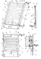
- the roof covering element shown in FIGS. 1 to 3 has a plate body 1 in the form of a panel 2, on which lateral under and overlap strips 3 and 4 are formed.
- the plate body is extended by a cover apron 5 which covers the following plate body in the covering position.
- the roofing element is expediently designed in its shape and dimensions so that it is interchangeable with a conventional, standardized element. Therefore, it can also be used retrospectively in every roof covering in a more or less large area. Differences in fit on the connecting walls to the conventional roof skin can be easily sealed with sealants or tapes.
- a meandering flow channel 7 is formed on the lower surface of the plate body and extends approximately over the entire width of the plate.
- this channel connects to a plug hole 9, which ends flush with the top edge 10 of the panel.
- a plug hole 11 is provided at the lower channel end 12 at a distance from the upper 9 which corresponds to the distance between the covering or roof battens 23.
- the lower plug bore 11 is therefore provided at the transition to the cover apron 5.
- the two plug holes are expediently aligned with one another on the longitudinal center line.
- a plug-in tube 14 (FIG. 4) is used to connect the plug-in bores and has sealing rings 16 which are fitted on its two plug-in heads 15.
- the two plug-in heads are connected by means of a flexible tube 17.
- the plug-in holes and the plug-in heads are made to fit.
- the inserts 20, 21 made of a suitable material can be introduced into housings 18, 19 formed on the table or pan.
- hook-in lugs 22 are still formed, which engage in the roof battens 23.
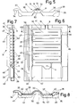
- a covering element according to FIGS. 5 to 8 has a pan-shaped plate body 31 in the form of a conventional roof tile. This forms, for example, a central roller 32 and on one long side an overlap strip 33 with overlap ribs 34 on the underside. On the other long side of the plate body, the matching lower gripping ribs 36 are formed on a lower gripping bar 35.
- a flow channel 37 in turn extends to the width of the actual plate body with the two flats 38 and the central roller 32. This flow channel is, as before, molded into the plate body in such a way that it is essentially formed out of the lower surface of the plate body, but the surface remains smooth.
- the plug-in hole 9 on the pan head ends flush with this front edge, while the plug-in hole 11 (FIGS. 6, 7) at the foot end at the beginning of the cover apron 39 is expediently designed as an inclined indentation 49.
- the flow channels 7, 37 are advantageously molded into a plate body made of plastic by blow molding.
- a deformable plastic such as appropriately stabilized polypropylene, is particularly well suited for the production of such roofing elements.
- the other profiles on the top and bottom surface can also be formed well and precisely. The fact that a preform is still formed in the plastic state by means of a blow mold creates so-called pinch edges or pinch folds 40 between the cavities of the flow channel, the wall thickness of which is thicker than the channel wall.
- top and bottom ribs 41, 42 of the roof tile can also be hollow, as shown in FIG. 7. This can also apply to the cover apron 39 if it is stiffened by means of an additional cavity wall 43.
- hollow limiting beads 45, 46 are expediently also formed along the lateral overlapping and undergripping strips 33, 35 of the roof tile, which extend between a head-side slat support section 47 and a covering section 48. Since these limiting beads are thus in the roof covering position between the roof battens, they can be sufficiently high to form a bed for receiving a heat insulating material 53 (FIG. 8 dotted). Likewise, the space between the upper and lower gripping strips 33 and 35 rising above the flow channel in the area of the slat support and covering sections 47 and 48 can be filled with a heat insulating material 54 (FIG. 8 dotted). Immediately after the plate body has been formed, these insulating layers can be easily and easily applied to it and permanently attached by gluing or the like.
- the plug hole 9 on the head side, as shown in FIG. 2, is formed into a round hole in that pinch folds 51 are formed on both sides, which are also connected to the lateral head ribs 41.
- the plug hole 11 at the outlet end of the flow channel is shaped as an indentation 49 in a hollow extension 50 at the channel end.
- the flow channel 37 in its meandering arrangement, takes up essentially the entire plate surface exposed to the sun, except for the narrow intermediate webs 40.
- a baffle wall 55 with passage openings 56 on both sides is provided.
- the cavities not flowed through by the heat transfer fluid can also be filled with a liquid or a to increase its weight be filled with other solid material, so that this roofing element then also corresponds in weight to a conventional one.
- the under and overlap strips, folds or the like can also be adapted to other profiles. If these strips overlap, it is particularly useful in the case of the table shape 7 to taper them slightly towards the top of the head, so that the plate bodies can be placed on top of one another in a well-sealed manner. It can also be expedient to provide a foot rib along the free edge of the plate.
- the plate size can also correspond to a multiple of a standard size for all versions.
- the covered area can also be provided with a continuous insulating shell (not shown).
Landscapes
- Engineering & Computer Science (AREA)
- Chemical & Material Sciences (AREA)
- Mechanical Engineering (AREA)
- Sustainable Development (AREA)
- Sustainable Energy (AREA)
- Thermal Sciences (AREA)
- Physics & Mathematics (AREA)
- Combustion & Propulsion (AREA)
- Life Sciences & Earth Sciences (AREA)
- General Engineering & Computer Science (AREA)
- Architecture (AREA)
- Civil Engineering (AREA)
- Structural Engineering (AREA)
- Roof Covering Using Slabs Or Stiff Sheets (AREA)
- Photovoltaic Devices (AREA)
Priority Applications (1)
| Application Number | Priority Date | Filing Date | Title |
|---|---|---|---|
| AT81107684T ATE12685T1 (de) | 1980-09-30 | 1981-09-28 | Dacheindeckungselement aus kunststoff zur gewinnung von sonnenenergie. |
Applications Claiming Priority (2)
| Application Number | Priority Date | Filing Date | Title |
|---|---|---|---|
| DE19803036897 DE3036897A1 (de) | 1980-09-30 | 1980-09-30 | Dacheindeckungselement aus kunststoff o.dgl. verformbarem werkstoff zur gewinnung von sonnenenergie |
| DE3036897 | 1980-09-30 |
Publications (2)
| Publication Number | Publication Date |
|---|---|
| EP0048982A1 true EP0048982A1 (fr) | 1982-04-07 |
| EP0048982B1 EP0048982B1 (fr) | 1985-04-10 |
Family
ID=6113231
Family Applications (1)
| Application Number | Title | Priority Date | Filing Date |
|---|---|---|---|
| EP81107684A Expired EP0048982B1 (fr) | 1980-09-30 | 1981-09-28 | Elément pour la toiture en matière plastique pour l'aquisition d'énergie solaire |
Country Status (3)
| Country | Link |
|---|---|
| EP (1) | EP0048982B1 (fr) |
| AT (1) | ATE12685T1 (fr) |
| DE (2) | DE3036897A1 (fr) |
Cited By (7)
| Publication number | Priority date | Publication date | Assignee | Title |
|---|---|---|---|---|
| DE3221490A1 (de) * | 1982-06-07 | 1983-12-08 | Hans 6507 Ingelheim Weitzel | Dacheindeckungselement, insbesondere zur gewinnung von sonnenenergie |
| GB2198759A (en) * | 1986-12-12 | 1988-06-22 | David Turner Coates | Solar heat collecting cladding component |
| EP0663487A1 (fr) * | 1994-01-13 | 1995-07-19 | Ubbink Nederland B.V. | Tuile de ventilation pour toits |
| WO2007102571A1 (fr) | 2006-03-09 | 2007-09-13 | Ono Pharmaceutical Co., Ltd. | Agent thérapeutique contre une maladie fonctionnelle du cerveau |
| WO2017129813A1 (fr) * | 2016-01-29 | 2017-08-03 | Paxos Consulting & Engineering GmbH & Co. KG | Tuile solaire thermique comprenant un élément de raccordement variable en longueur |
| US10673373B2 (en) | 2016-02-12 | 2020-06-02 | Solarcity Corporation | Building integrated photovoltaic roofing assemblies and associated systems and methods |
| US20220060141A1 (en) * | 2020-08-24 | 2022-02-24 | Colin Felton | Labor Saving Solar Roofing Shingle |
Families Citing this family (6)
| Publication number | Priority date | Publication date | Assignee | Title |
|---|---|---|---|---|
| AT399190B (de) * | 1987-12-15 | 1995-03-27 | Vanovsek Wolfgang Dipl Ing Dr | Sonnenkollektor |
| DE4011289A1 (de) * | 1990-04-06 | 1991-01-03 | Joachim Kahle | Keramikglas-sonnenkollektoren zur einarbeitung in dachziegeln herkoemmlicher formen und typen |
| DE9004032U1 (de) * | 1990-04-06 | 1990-09-13 | Kahle, Joachim, 5650 Solingen | Keramikglas-Sonnenkollektor |
| DE19600579C1 (de) * | 1996-01-10 | 1997-04-10 | Viessmann Gmbh & Co | Dachabdeckelement |
| DE19902532C1 (de) * | 1999-01-22 | 2000-08-17 | Kurt Roes | Dacheindeckungselement und Fassadenverkleidungselement zur thermischen Isolation und zur solaren Energiegewinnung |
| ITBS20060204A1 (it) * | 2006-11-29 | 2008-05-30 | Ideasol S R L | Piastrella adatta all'utilizzazione di energia solare per il riscaldamento di un liquido, ad esempio acqua |
Citations (5)
| Publication number | Priority date | Publication date | Assignee | Title |
|---|---|---|---|---|
| AT297307B (de) * | 1963-07-08 | 1972-02-15 | Battenfeld Geb | Verfahren und blasform zur herstellung von offenen hohlkoerpern durch formblasen |
| DE2529095A1 (de) * | 1975-06-30 | 1977-01-27 | Geb Nirschl Erna Mari Daeumler | Hohles, auf daechern oder anderen sonnenbestrahlten flaechen anbringbares plattenelement |
| DE2724314A1 (de) * | 1976-06-11 | 1977-12-22 | George Thomas Straza | Sonnenbeheiztes schindeldach |
| DE2818475A1 (de) * | 1978-01-21 | 1979-10-31 | Bauer Geb Koerzdoerfer Ingebor | Dachziegel und dazugehoerige anordnung fuer die gewinnung der sonnenenergie |
| DE2851810A1 (de) * | 1978-11-28 | 1980-06-04 | Dieter Ing Grad Wendisch | Plattenelement zur nutzung einstrahlender sonnenenergie |
Family Cites Families (6)
| Publication number | Priority date | Publication date | Assignee | Title |
|---|---|---|---|---|
| DE7611233U1 (de) * | 1976-04-09 | 1976-08-12 | Bittner, Alfred, 8051 Langenbach | Sonnenkollektor |
| DE7613567U1 (de) * | 1976-04-29 | 1977-12-22 | Felske, Artur R., 6238 Hofheim | Sonnenkollektor |
| DE2640333A1 (de) * | 1976-09-08 | 1978-03-09 | Harald Martin Schmelow | Kollektorpfanne |
| GB2031141B (en) * | 1978-05-24 | 1983-03-23 | Offshore Eng Ltd | Solar panels |
| DE2840806A1 (de) * | 1978-09-20 | 1980-04-03 | Werner Huenten | Sonnenkollektoren als dachpfannen |
| DE8000101U1 (de) * | 1980-01-04 | 1980-07-03 | Iduso Gesellschaft Zur Foerderung Und Verwertung Kreativer Ideen Mbh, 5300 Bonn | Dachpfanne |
-
1980
- 1980-09-30 DE DE19803036897 patent/DE3036897A1/de not_active Withdrawn
-
1981
- 1981-09-28 DE DE8181107684T patent/DE3169854D1/de not_active Expired
- 1981-09-28 AT AT81107684T patent/ATE12685T1/de not_active IP Right Cessation
- 1981-09-28 EP EP81107684A patent/EP0048982B1/fr not_active Expired
Patent Citations (5)
| Publication number | Priority date | Publication date | Assignee | Title |
|---|---|---|---|---|
| AT297307B (de) * | 1963-07-08 | 1972-02-15 | Battenfeld Geb | Verfahren und blasform zur herstellung von offenen hohlkoerpern durch formblasen |
| DE2529095A1 (de) * | 1975-06-30 | 1977-01-27 | Geb Nirschl Erna Mari Daeumler | Hohles, auf daechern oder anderen sonnenbestrahlten flaechen anbringbares plattenelement |
| DE2724314A1 (de) * | 1976-06-11 | 1977-12-22 | George Thomas Straza | Sonnenbeheiztes schindeldach |
| DE2818475A1 (de) * | 1978-01-21 | 1979-10-31 | Bauer Geb Koerzdoerfer Ingebor | Dachziegel und dazugehoerige anordnung fuer die gewinnung der sonnenenergie |
| DE2851810A1 (de) * | 1978-11-28 | 1980-06-04 | Dieter Ing Grad Wendisch | Plattenelement zur nutzung einstrahlender sonnenenergie |
Cited By (11)
| Publication number | Priority date | Publication date | Assignee | Title |
|---|---|---|---|---|
| DE3221490A1 (de) * | 1982-06-07 | 1983-12-08 | Hans 6507 Ingelheim Weitzel | Dacheindeckungselement, insbesondere zur gewinnung von sonnenenergie |
| EP0096413B1 (fr) * | 1982-06-07 | 1986-09-03 | Hans Weitzel | Elément de couverture de toit notamment pour capter de l'énergie solaire |
| GB2198759A (en) * | 1986-12-12 | 1988-06-22 | David Turner Coates | Solar heat collecting cladding component |
| GB2198759B (en) * | 1986-12-12 | 1991-02-06 | David Turner Coates | Cladding component. |
| EP0663487A1 (fr) * | 1994-01-13 | 1995-07-19 | Ubbink Nederland B.V. | Tuile de ventilation pour toits |
| NL9400059A (nl) * | 1994-01-13 | 1995-08-01 | Ubbink Nederland Bv | Dakpan voor ventilatiedoeleinden. |
| WO2007102571A1 (fr) | 2006-03-09 | 2007-09-13 | Ono Pharmaceutical Co., Ltd. | Agent thérapeutique contre une maladie fonctionnelle du cerveau |
| WO2017129813A1 (fr) * | 2016-01-29 | 2017-08-03 | Paxos Consulting & Engineering GmbH & Co. KG | Tuile solaire thermique comprenant un élément de raccordement variable en longueur |
| US10673373B2 (en) | 2016-02-12 | 2020-06-02 | Solarcity Corporation | Building integrated photovoltaic roofing assemblies and associated systems and methods |
| US20220060141A1 (en) * | 2020-08-24 | 2022-02-24 | Colin Felton | Labor Saving Solar Roofing Shingle |
| US12395116B2 (en) * | 2020-08-24 | 2025-08-19 | Colin Felton | Labor saving solar roofing shingle |
Also Published As
| Publication number | Publication date |
|---|---|
| DE3036897A1 (de) | 1982-04-22 |
| ATE12685T1 (de) | 1985-04-15 |
| DE3169854D1 (en) | 1985-05-15 |
| EP0048982B1 (fr) | 1985-04-10 |
Similar Documents
| Publication | Publication Date | Title |
|---|---|---|
| DE2354333C3 (de) | Kastendachrinne aus stranggepreßtem Kunststoff | |
| EP0048982B1 (fr) | Elément pour la toiture en matière plastique pour l'aquisition d'énergie solaire | |
| DE8137938U1 (de) | Gasdicht verschlossene hohlkammerplatte aus kunststoff | |
| DE2804301C2 (de) | Sonnenkollektor für Dächer oder Fassaden von Gebäuden | |
| DE3027045A1 (de) | Flach-hohlkoerper, insbesondere lueftungs- und drainage- bzw. absorber-platte | |
| DE2712387A1 (de) | Sonnenkollektor | |
| DE3616733C2 (fr) | ||
| DE3221490C2 (de) | Dacheindeckungselement zur Gewinnung von Sonnenenergie | |
| CH658698A5 (de) | Hohlbaustein. | |
| DE3003865C2 (de) | Dacheindeckung aus Dachziegeln, in denen Wärmetauscherrohre angeordnet sind | |
| DE2100074C3 (de) | Mantelfullstoffwand od dgl | |
| DE2111730A1 (de) | Bauelement fuer Gebaeudewaende | |
| EP0018543B1 (fr) | Collecteur d'énergie solaire | |
| DE69713504T2 (de) | Bauelement | |
| DE2430053C2 (de) | Heizwand für Horizontalkoksofenbatterien | |
| DE2806586A1 (de) | Solarzelle | |
| DE2614145A1 (de) | Installationskanal, zur ableitung der aufgefangenen sonnenenergie | |
| DE2924305C2 (de) | Hohlplattenförmiges Wärmeaustauschelement | |
| EP0073298B1 (fr) | Palette pour la fabrication de tuiles en béton dans un procédé d'éxtrusion | |
| DE2846451A1 (de) | Vorrichtung zur erzeugung nutzbarer waerme aus sonnenstrahlung | |
| DE3025394A1 (de) | Waermedaemmplatte | |
| DE3534114A1 (de) | Modulares verkleidungspaneel fuer gebaeude | |
| DE8318374U1 (de) | Belagbelag zur verwendung bei aussenflaechen von gebaeuden oder freianlagen | |
| DE2501323A1 (de) | Element zum verkleiden von aussenflaechen an gebaeuden | |
| DE2165977A1 (de) | Mantelbetonwand oder dergleichen |
Legal Events
| Date | Code | Title | Description |
|---|---|---|---|
| PUAI | Public reference made under article 153(3) epc to a published international application that has entered the european phase |
Free format text: ORIGINAL CODE: 0009012 |
|
| AK | Designated contracting states |
Designated state(s): AT BE CH DE FR GB IT NL SE |
|
| 17P | Request for examination filed |
Effective date: 19820813 |
|
| ITF | It: translation for a ep patent filed | ||
| GRAA | (expected) grant |
Free format text: ORIGINAL CODE: 0009210 |
|
| AK | Designated contracting states |
Designated state(s): AT BE CH DE FR GB IT LI NL SE |
|
| REF | Corresponds to: |
Ref document number: 12685 Country of ref document: AT Date of ref document: 19850415 Kind code of ref document: T |
|
| PG25 | Lapsed in a contracting state [announced via postgrant information from national office to epo] |
Ref country code: SE Effective date: 19850430 |
|
| REF | Corresponds to: |
Ref document number: 3169854 Country of ref document: DE Date of ref document: 19850515 |
|
| ET | Fr: translation filed | ||
| PLBE | No opposition filed within time limit |
Free format text: ORIGINAL CODE: 0009261 |
|
| STAA | Information on the status of an ep patent application or granted ep patent |
Free format text: STATUS: NO OPPOSITION FILED WITHIN TIME LIMIT |
|
| 26N | No opposition filed | ||
| GBPC | Gb: european patent ceased through non-payment of renewal fee | ||
| PG25 | Lapsed in a contracting state [announced via postgrant information from national office to epo] |
Ref country code: GB Free format text: LAPSE BECAUSE OF NON-PAYMENT OF DUE FEES Effective date: 19881118 |
|
| ITTA | It: last paid annual fee | ||
| PGFP | Annual fee paid to national office [announced via postgrant information from national office to epo] |
Ref country code: FR Payment date: 19970929 Year of fee payment: 17 Ref country code: AT Payment date: 19970929 Year of fee payment: 17 |
|
| PGFP | Annual fee paid to national office [announced via postgrant information from national office to epo] |
Ref country code: DE Payment date: 19970930 Year of fee payment: 17 |
|
| PGFP | Annual fee paid to national office [announced via postgrant information from national office to epo] |
Ref country code: BE Payment date: 19971003 Year of fee payment: 17 |
|
| PGFP | Annual fee paid to national office [announced via postgrant information from national office to epo] |
Ref country code: CH Payment date: 19971008 Year of fee payment: 17 |
|
| PG25 | Lapsed in a contracting state [announced via postgrant information from national office to epo] |
Ref country code: AT Free format text: LAPSE BECAUSE OF NON-PAYMENT OF DUE FEES Effective date: 19980928 |
|
| PG25 | Lapsed in a contracting state [announced via postgrant information from national office to epo] |
Ref country code: LI Free format text: LAPSE BECAUSE OF NON-PAYMENT OF DUE FEES Effective date: 19980930 Ref country code: CH Free format text: LAPSE BECAUSE OF NON-PAYMENT OF DUE FEES Effective date: 19980930 Ref country code: BE Free format text: LAPSE BECAUSE OF NON-PAYMENT OF DUE FEES Effective date: 19980930 |
|
| BERE | Be: lapsed |
Owner name: WEITZEL HANS Effective date: 19980930 |
|
| REG | Reference to a national code |
Ref country code: CH Ref legal event code: PL |
|
| PG25 | Lapsed in a contracting state [announced via postgrant information from national office to epo] |
Ref country code: FR Free format text: LAPSE BECAUSE OF NON-PAYMENT OF DUE FEES Effective date: 19990531 |
|
| PG25 | Lapsed in a contracting state [announced via postgrant information from national office to epo] |
Ref country code: DE Free format text: LAPSE BECAUSE OF NON-PAYMENT OF DUE FEES Effective date: 19990701 |
|
| REG | Reference to a national code |
Ref country code: FR Ref legal event code: ST |
|
| PGFP | Annual fee paid to national office [announced via postgrant information from national office to epo] |
Ref country code: NL Payment date: 19990930 Year of fee payment: 19 |
|
| PG25 | Lapsed in a contracting state [announced via postgrant information from national office to epo] |
Ref country code: NL Free format text: LAPSE BECAUSE OF NON-PAYMENT OF DUE FEES Effective date: 20010401 |
|
| NLV4 | Nl: lapsed or anulled due to non-payment of the annual fee |
Effective date: 20010401 |