EP0048991B1 - Méthode et dispositif pour le traitement des conditions d'interruption pendant le déroulement des opérations dans les systèmes de traitement de données à commande microprogrammée - Google Patents
Méthode et dispositif pour le traitement des conditions d'interruption pendant le déroulement des opérations dans les systèmes de traitement de données à commande microprogrammée Download PDFInfo
- Publication number
- EP0048991B1 EP0048991B1 EP81107744A EP81107744A EP0048991B1 EP 0048991 B1 EP0048991 B1 EP 0048991B1 EP 81107744 A EP81107744 A EP 81107744A EP 81107744 A EP81107744 A EP 81107744A EP 0048991 B1 EP0048991 B1 EP 0048991B1
- Authority
- EP
- European Patent Office
- Prior art keywords
- clock pulse
- test
- zyk
- cycle
- clock
- Prior art date
- Legal status (The legal status is an assumption and is not a legal conclusion. Google has not performed a legal analysis and makes no representation as to the accuracy of the status listed.)
- Expired
Links
Images


Classifications
-
- G—PHYSICS
- G06—COMPUTING OR CALCULATING; COUNTING
- G06F—ELECTRIC DIGITAL DATA PROCESSING
- G06F11/00—Error detection; Error correction; Monitoring
- G06F11/07—Responding to the occurrence of a fault, e.g. fault tolerance
- G06F11/0703—Error or fault processing not based on redundancy, i.e. by taking additional measures to deal with the error or fault not making use of redundancy in operation, in hardware, or in data representation
- G06F11/0706—Error or fault processing not based on redundancy, i.e. by taking additional measures to deal with the error or fault not making use of redundancy in operation, in hardware, or in data representation the processing taking place on a specific hardware platform or in a specific software environment
- G06F11/073—Error or fault processing not based on redundancy, i.e. by taking additional measures to deal with the error or fault not making use of redundancy in operation, in hardware, or in data representation the processing taking place on a specific hardware platform or in a specific software environment in a memory management context, e.g. virtual memory or cache management
-
- G—PHYSICS
- G06—COMPUTING OR CALCULATING; COUNTING
- G06F—ELECTRIC DIGITAL DATA PROCESSING
- G06F11/00—Error detection; Error correction; Monitoring
- G06F11/07—Responding to the occurrence of a fault, e.g. fault tolerance
- G06F11/0703—Error or fault processing not based on redundancy, i.e. by taking additional measures to deal with the error or fault not making use of redundancy in operation, in hardware, or in data representation
- G06F11/0751—Error or fault detection not based on redundancy
-
- G—PHYSICS
- G06—COMPUTING OR CALCULATING; COUNTING
- G06F—ELECTRIC DIGITAL DATA PROCESSING
- G06F11/00—Error detection; Error correction; Monitoring
- G06F11/07—Responding to the occurrence of a fault, e.g. fault tolerance
- G06F11/14—Error detection or correction of the data by redundancy in operations
- G06F11/1402—Saving, restoring, recovering or retrying
- G06F11/1405—Saving, restoring, recovering or retrying at machine instruction level
- G06F11/141—Saving, restoring, recovering or retrying at machine instruction level for bus or memory accesses
Definitions
- the invention relates to a method and an arrangement for handling interruption conditions during the workflow in data processing systems with memory control and microprogram control, which is dependent on a central clock generator which generates several clock signals for the execution of an elementary operation per working cycle of the microprogram control by means of a clock chain and when a Interruption condition can be interrupted by a monitoring device in connection with a test device at the end of the current work cycle.
- a microprogram is a sequence of elementary operations (microinstructions) that together define a macroinstruction; see. Löbel, Müller,, Schmid, Lexikon der technik, p. 340.
- the check for an error and the stop of the generator supplying the work cycles are coupled with one another in such a way that all test points of the system are queried with a test cycle inserted into this at the end of the machine cycle and if an error is present the clock generator is stopped during a time when all of the data in the registers related to the operation being performed is still present. Stopping the system at the last cycle in the machine cycle also has the advantage that a simple restart is possible after replacing the incorrect data in the registers.
- an analysis network is therefore coupled to the error register working as a monitoring device as a test device, which stops the clock generator via a pause generator before the cycle of the work cycle that initiates a new elementary operation and prepares an error handling routine, which then after the pause time specified by the pause generator has elapsed, the clock generator is released for the blocked clock.
- This known arrangement thus only reacts to errors that require a transfer to an error handling routine.
- interruptions in the normal process can not only be caused by errors of different Hardware errors or program access errors, but also due to other events, e.g. Stop or reset of the system, address comparison with different reactions. It is necessary that the system always assumes a clear and reproducible state with every interruption of the normal process, which enables a return to the normal work process without difficulty and excludes critical time conditions.
- the parallel work of independent functional units of the system must not be unnecessarily hampered by this.
- the clock generator has devices for deriving a further test signal for the monitoring device when the clock generator is restarted after a generator stop.
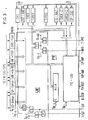
- the central processor ZP is subdivided into several sub-units SE, VE and ZE with a common microprogram control, to which tasks of the central processor ZP are permanently assigned, which can in part be carried out in parallel with one another.
- the subunit VE represents the actual processing unit of the central processor, which links the operands and thereby carries out arithmetic, logical, shift and transfer functions in a manner known per se.
- the subunit ZE has the task of handling the traffic between the storage system PLC and the central processor ZP and of supplying the processing unit VE with data and the control unit SE with microinstructions. When accessing data with virtual addresses, it also performs address translation into real addresses.
- the sub-unit SE controls the entire microprogram sequence in the central processor ZP as well as the interfaces to the service processor SVP and, if appropriate, to other processors, such as input / output processors.
- this unit can perform its own functions in parallel to the processing unit VE and the access unit ZE, e.g. Jump, set and count functions. Provide direct operands, etc.
- This unit accordingly comprises a reloadable microinstruction memory and the microinstruction register for the other subunits VE and ZE as well as devices for subsequent address calculation.
- a clock supply TV is also provided in a manner known per se, which periodically supplies the subunits with work cycles.
- a monitoring device UE for detecting interruption events and a test device PE is provided, which works closely with the clock supply TV and takes control when the normal workflow of the central processor ZP is interrupted.
- the clock supply TV shown in FIG. 2 is divided into the clock generator TG, which supplies cyclically successive basic clocks T, to T n for the subsequent clock chains TK ... for supplying the individual sub-units SE, VE and ZE of the central processor ZP in FIG. 1 .
- the TK-AW device is selected in conjunction with the TK-UM cycle chain switchover to select the individual clock chains required.
- the clock generator is started via the TG-START input by the service processor SVP or by the memory system PLC after a memory access, if the system was previously in the stop state, with the first clock T j .
- the clock generator TG is normally stopped by the test device PE of the central processor ZP via the input TG-STOP, specifically at the end of a clock cycle, that is to say after the clock T n has been delivered . None of the clocks or clock phases T 1 to T n is then effective.
- a total of three basic clock chains are provided for the individual processor subunits VE, ZE and SE and two basic clock chains for the cycle types FA and PE, which control the subsequent address calculation in the control unit SE or the reaction by the test device PE.
- These five basic clock chains are combined in four clock chains TK-PE, TK-FA, TK-SE and TK-VE / ZE, some of which can run parallel to each other.
- the device TK-UM first makes a preselection between the clock chain TK-PE and all other clock chains.
- This device consists of a conventional D flip-flop FF, which is clocked with the trailing edge of the last clock T n of the clock generator TG.
- the last clock T PE-n of the clock chain TK-PE acts on the reset input R of this flip-flop FF, so that a switch is made to a work cycle after each test cycle, while the switch from the work cycle to the test cycle is signaled by a signal T-UM1 from the Test device PE is triggered on input D.
- the flip-flop FF can be set statically via the set input S with the signal T-UM2 by the monitoring device UE and thus switched over to a test cycle when the clock generator TG is started again after a generator stop, which is triggered by the signal TG-AN , so that even after the clock generator TG has restarted, a test cycle can initially run.
- the further chain selection depends, for example, on validity bits of the associated microinstructions in the control device SE. These are converted in a manner known per se by a link arrangement DEC into control signals for the AND elements connected upstream of the selectable clock chains.
- the clock chain TK-PE supplies the test device PE during a test cycle which is switched on as required in the normal workflow of the central processor.
- This chain and this test cycle therefore never run parallel to the other clock chains shown for the central processor ZP.
- the test cycle can easily run parallel to an access to the memory system PLC.
- the clock chain TK-FA for the subsequent address calculation in the control device SE normally runs parallel to the clock chain TK-VE and / or TK-SE in order to be able to provide the next microinstruction; however, it runs alone if entry addresses are to be calculated for an address conversion or an error handling routine or if not all commands are available in parallel with commands for the unit VE or ZE parallel to the control unit SE.
- the clock chain TK-VE / ZE is provided jointly for the subunits VE and ZE of the central processor ZP. However, there is a difference between them with regard to the last cycles T ZE - N and T VE-n in that the clock T ZE-N is not blocked when the last cycle clocks are generally blocked.
- the clock lock is carried out by the two signals T-Sp1 and T-Sp2 of the monitoring device UE, in that when both signals are present, all the last cycle clocks, ie T FA - N , Ts E - n TvE-n and T ZE-n , are blocked, while with the signal T-Sp2 alone all these clocks are blocked with the exception of the clock T zE-n .
- the monitoring device UE in FIG. 1 is also used during each working cycle controlled in order to check whether an event interrupting the normal sequence of the central processor ZP has occurred and, accordingly, is to be switched over to a test cycle for the test device PE.
- the clock supply TV can be designed based on that of DE-AS 26 19 445 or that of DE-OS 29 07 170.
- the monitoring and testing device UE / PE shown in Fig. 3 essentially consists of a buffer register MERB and the downstream actual machine error register MER, some flags CYCL, STOP-ANF, SREX, EOREX, EPROC, TG-HALT and SP-ZUG, e.g. in the form of flip-flops, which may be inserted in other registers, two counters SREX-Z and EOREX-Z and a logic logic PE-LOG, as well as some logic elements for the monitoring device UE.
- the buffer register MERB and the flags STOP-ANF, SREX and EOREX are continuously checked by the monitoring device UE.
- two points in time are decisive, one towards the end of each EO cycle with a clock window T FA- formed from clock cycles, for example T FA - ( n - 1 ) and TFA-n 'of the clock chain TK-FA for controlling the subsequent addresses.
- T FA- formed from clock cycles, for example T FA - ( n - 1 ) and TFA-n 'of the clock chain TK-FA for controlling the subsequent addresses.
- F and on the other hand the point in time when the clock generator TG of the clock supply TV is started again after a generator stop.
- a changeover signal is formed for the changeover to a test cycle for the test device PE, specifically the signal T-UM1 depending on the clock window T FA - F and the signal T-UM2 when starting the clock generator TG in connection with the signal TG-AN.
- This ensures that a test cycle is inserted after each clock generator start and can thus be recognized whether new errors or interrupt requests have occurred in the meantime.
- the markers SREX and EOREX which are set in the event of an automatic repetition of an incorrectly executed memory access or an elementary operation, ensure that a test cycle is inserted after each repetition in order to be able to check whether the repetition was successful and whether there are further interrupt requests.
- the monitoring device UE carries out two further tests simultaneously.
- the input variables for the elementary operation cannot be changed and the elementary operation can therefore be repeated immediately, the result clocks and thus the clocks for changing the input variables for an elementary operation to be carried out are blocked in the event of an EO error.
- these are the last clock phases n of the clock chains TK-FA, TK-SE, TK-VE / ZE. This test must therefore be carried out early enough, which also explains the start of the clock window T FA-F, for example with the clock phase (n-1).
- the link network PE-LOG of the test device PE is also dependent on the information content of the buffer register MERB. Both the switchover to a test cycle and the work of the test device PE are thus controlled by the buffer register MERB, while errors and interruption requests can be collected in the subsequent machine error register MER without the changeover controlled by the buffer register MERB being impeded. For this purpose, bits set in the MERB buffer register for new interrupt requests are each transferred to the machine error register MER at the beginning of a test cycle and the MERB buffer register is reset at the end of the test cycle.
- the markers and counters shown are also required for the work of the test device PE.
- the counters SREX-Z and EOREX-Z monitor the number of repetitions, so after a specified number of repetitions has expired the error handling routine FB-ROUT can be transferred.
- the EPROC flag indicates the status of the error handling and serves as protection against double errors, while the TG-HALT flag, when set, leads to a generator stop at the end of a test cycle.
- the SP-ZUG flag is set when a memory access is started. All flags shown can be monitored by the PE-LOG link network and can be influenced by this except for the CYCL flag. Furthermore, the flags CYCL and STOP-ANF can be controlled by the service processor SVP and the flags SP-ZUG by the access unit ZE.
- a work cycle EO-Zyk for an elementary operation and a test cycle P-Zyk in the form of time slices with the clock phases 1 to n are the Sequence-controlling chains shown.
- the work cycle is normally started when the clock generator TG is enabled, ie with the signal TG-START, and at the end of the work cycle a new work cycle is started with an undisturbed process.
- the monitoring device UE is activated with the clock window T FA - F , which checks whether an error or an interruption request has occurred in the meantime or whether a reaction is otherwise necessary.
- These reactions consist in the fact that if the flag CYCL in FIG. 3 is set, the clock phase n must be blocked for all chains with the exception of the clock chain TK-ZE - signal T-Sp2 - or that in the event of an EO error the clock phase n of all clock chains must be blocked - Signal T-Sp1 / 2- and switch over to a test cycle - Signal T-UM1. This is indicated in Fig.
- the start signal TG-START is also routed via a switch of the clock chain changeover TK-UM.
- the switch to an upstream test cycle P-Zyk is carried out by the signal T-UM2 of the monitoring device UE, which carries out a test independently of the clock T FA-F even when the signal TG-AN is present.
- test cycle is only switched over with the signal T-UM1 or T-UM2.
- This decision logic of the monitoring device UE can be implemented in a conventional manner with AND and OR gates, as shown in FIG. 3.
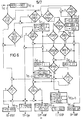
- FIG. 6 shows, likewise in the form of a flow chart, the decision logic for the link network PE-LOG of the test device PE during a test cycle. All decision lozenges are checked with a static signal T PE - F , which, as shown in FIG. 2, is the same as the selection signal for the clock chain TK-PE. The individual clock phases of the clock chain TK-PE are embedded in this signal, which trigger the individual reactions identified by framing boxes. The position in the flowchart according to FIG. 6 therefore says nothing about the reaction time during the test cycle, only the clock phases of the test cycle indicated next to the boxes are decisive, while the form of presentation was chosen more for reasons of clarity.
- the STOP-ANF flag is set first with the clock phase d, and second with phase e the transfer from the buffer register MERB into the machine error register M ER follows and with the signal SP-ANF the repetition of a memory access.
- test cycle The division of the test cycle into individual clock phases thus guarantees that the reactions run in a timely manner during the test cycle.
- the memory errors have the highest priority because much more time is required to access the memory compared to the duration of a work cycle, and postponing it results in unnecessary delays.
- the next lowest priority is assigned to an EO error because the normal process can only continue it makes sense if an elementary operation has been carried out correctly and without errors.
- a check is carried out to determine whether it is an error during an error handling procedure and thus a double error. If the EPROC flag is not set and therefore there is no double error, the SREX and EOREX flags are deleted and the EPROC flag is set. In addition, an error handling routine is initiated with signal FB-ROUT at the end of the test cycle in a manner known per se. However, the prerequisite for this is that the machine is not in the cyclically working state, i.e. the CYCL flag is not set. Furthermore, the system switches to the next work cycle.
- the flags STOP-ANF and TG-STOP are set first. Furthermore, if the SP-ZUG flag is not set because there is currently no memory access, the STOP-ANF flag is deleted at the end of the test cycle and the SVP service processor is requested with the SVP-ANF signal. If, on the other hand, the SP-ZUG flag is set, the stop request is not deleted and the service processor is not requested. In both cases, however, the clock generator is stopped at the end of the test cycle with the signal TG-STOP because of the previously set flag TG-STOP until the clock generator TG is started again by the service processor SVP or the memory system PLC (FIG. 2).
- reaction mode it is checked whether there is an address comparison with entry into the error handling routine FB-ROUT as reaction mode or not. If so, the reaction is the same as when the GRS-FLAG is set. In the other case, it is checked with the lowest priority whether there is a stop request and the STOP-ANF flag is therefore set. If there is a stop request, the TOG-HALT flag is set and, depending on whether there is a memory access, the clock generator is stopped, as already explained, with or without a simultaneous request for the service processor SVP.
- connection network PE-LOG can in turn be implemented in a simple manner with conventional AND and OR gates.
- FIG. 7 shows the sequence when an EO error occurs during a work cycle for the elementary operation E01, in which the clock chains TK-FA, TK-VE and TK-SE run in parallel, ie in addition to the execution of a follow-up address calculation for the next elementary operation E02 to be carried out the processing unit VE and the control unit SE work in parallel.
- a switch is made to a test cycle at the end of the work cycle for elementary operation E01 and the EO error is recognized as such.
- the result is a repetition of elementary operation E01 and the execution of another test cycle. Since the error occurs again, there is another repeat and another test cycle. Since no further errors are found, it can be concluded that elementary operation E01 has been successfully completed.
- the work cycle for elementary operation E02 is therefore initiated, and since this is also carried out without errors, the work cycle for elementary operation E03 is initiated without any further interruption by a test cycle. If the machine works correctly, there is no interruption of the normal process by a test cycle.
- the repetition of the faulty elementary operation E01 does not lead to the goal. It is repeated 16 times in total.
- the test cycle then leads to a jump into the error handling routine, with the result that initially only the clock chain TK-FA runs in order to calculate the start address for the error handling routine, with which the error program is then started, which in the subsequent work cycles the control unit SE and the Processing unit VE can act.
- Figure 9 illustrates memory access in parallel with the execution of elementary operations.
- the access unit ZE starts access to the storage system.
- pending elementary operations are processed independently.
- the duty cycle for elementary operation E02 is not error-free, so a test cycle is inserted and elementary operation E02 is repeated. Since the repetition is successful, the subsequent test cycle leads to the work cycle for elementary operation E03.
- a memory error is reported during this duty cycle.
- the test cycle initiated thereby starts the memory access again and stops the processing of further elementary operations until the memory reports the successful termination of the access and starts the stopped clock generator in FIG. 2 again. Due to the SREX flag set, the generator starts immediately with a test cycle. However, since the memory access retry was successful and there is no further interrupt request, the normal workflow continues with the execution of the elementary operations E04 and E05 etc.
- a test cycle is carried out first. Since the EO error has the highest priority as already explained, the elementary operation is repeated first. The other requirements are not lost because the address comparison is linked to the elementary operation to be carried out and is therefore repeated when it is repeated, and the STOP-ANF flag also remains set. In the subsequent test cycle, the repetition of the elementary operation is recognized as successful, the address comparison with entry into the error handling routine occurs again and can now be taken into account. A memory request occurs in the subsequent work cycle for calculating the entry address for the error handling routine.
Landscapes
- Engineering & Computer Science (AREA)
- Theoretical Computer Science (AREA)
- Quality & Reliability (AREA)
- Physics & Mathematics (AREA)
- General Engineering & Computer Science (AREA)
- General Physics & Mathematics (AREA)
- Test And Diagnosis Of Digital Computers (AREA)
- Retry When Errors Occur (AREA)
- Tests Of Electronic Circuits (AREA)
- Debugging And Monitoring (AREA)
Claims (15)
Priority Applications (1)
| Application Number | Priority Date | Filing Date | Title |
|---|---|---|---|
| AT81107744T ATE7742T1 (de) | 1980-09-30 | 1981-09-29 | Verfahren und anordnung zur behandlung von unterbrechungsbedingungen waehrend des arbeitsablaufes in datenverarbeitungsanlagen mit mikroprogrammsteuerung. |
Applications Claiming Priority (2)
| Application Number | Priority Date | Filing Date | Title |
|---|---|---|---|
| DE3036926A DE3036926C2 (de) | 1980-09-30 | 1980-09-30 | Verfahren und Anordnung zur Steuerung des Arbeitsablaufes in Datenverarbeitungsanlagen mit Mikroprogrammsteuerung |
| DE3036926 | 1980-09-30 |
Publications (2)
| Publication Number | Publication Date |
|---|---|
| EP0048991A1 EP0048991A1 (fr) | 1982-04-07 |
| EP0048991B1 true EP0048991B1 (fr) | 1984-05-30 |
Family
ID=6113241
Family Applications (1)
| Application Number | Title | Priority Date | Filing Date |
|---|---|---|---|
| EP81107744A Expired EP0048991B1 (fr) | 1980-09-30 | 1981-09-29 | Méthode et dispositif pour le traitement des conditions d'interruption pendant le déroulement des opérations dans les systèmes de traitement de données à commande microprogrammée |
Country Status (5)
| Country | Link |
|---|---|
| US (1) | US4653018A (fr) |
| EP (1) | EP0048991B1 (fr) |
| JP (1) | JPS6013493B2 (fr) |
| AT (1) | ATE7742T1 (fr) |
| DE (1) | DE3036926C2 (fr) |
Families Citing this family (14)
| Publication number | Priority date | Publication date | Assignee | Title |
|---|---|---|---|---|
| JPS59116858A (ja) * | 1982-12-23 | 1984-07-05 | Fujitsu Ltd | マシンチエツク割込み処理方式 |
| JPS62204345A (ja) * | 1986-03-05 | 1987-09-09 | Oki Electric Ind Co Ltd | マイクロコンピユ−タ |
| US4862352A (en) * | 1987-09-16 | 1989-08-29 | Motorola, Inc. | Data processor having pulse width encoded status output signal |
| US5428754A (en) * | 1988-03-23 | 1995-06-27 | 3Dlabs Ltd | Computer system with clock shared between processors executing separate instruction streams |
| US5325520A (en) * | 1992-01-03 | 1994-06-28 | Amdahl Corporation | Invoking hardware recovery actions via action latches |
| US6343363B1 (en) | 1994-09-22 | 2002-01-29 | National Semiconductor Corporation | Method of invoking a low power mode in a computer system using a halt instruction |
| US5949971A (en) * | 1995-10-02 | 1999-09-07 | International Business Machines Corporation | Method and system for performance monitoring through identification of frequency and length of time of execution of serialization instructions in a processing system |
| US5797019A (en) * | 1995-10-02 | 1998-08-18 | International Business Machines Corporation | Method and system for performance monitoring time lengths of disabled interrupts in a processing system |
| US5691920A (en) * | 1995-10-02 | 1997-11-25 | International Business Machines Corporation | Method and system for performance monitoring of dispatch unit efficiency in a processing system |
| US5748855A (en) * | 1995-10-02 | 1998-05-05 | Iinternational Business Machines Corporation | Method and system for performance monitoring of misaligned memory accesses in a processing system |
| US5751945A (en) * | 1995-10-02 | 1998-05-12 | International Business Machines Corporation | Method and system for performance monitoring stalls to identify pipeline bottlenecks and stalls in a processing system |
| US5752062A (en) * | 1995-10-02 | 1998-05-12 | International Business Machines Corporation | Method and system for performance monitoring through monitoring an order of processor events during execution in a processing system |
| US5729726A (en) * | 1995-10-02 | 1998-03-17 | International Business Machines Corporation | Method and system for performance monitoring efficiency of branch unit operation in a processing system |
| JP3323045B2 (ja) * | 1995-11-20 | 2002-09-09 | 東芝マイクロエレクトロニクス株式会社 | 情報処理装置 |
Citations (2)
| Publication number | Priority date | Publication date | Assignee | Title |
|---|---|---|---|---|
| US3548178A (en) * | 1968-01-18 | 1970-12-15 | Ibm | Computer error anticipator |
| DE2237925A1 (de) * | 1972-08-02 | 1974-02-21 | Ibm Deutschland | Verfahren in elektronischen datenverarbeitungssystemen zur fehleranalyse und -beseitigung |
Family Cites Families (12)
| Publication number | Priority date | Publication date | Assignee | Title |
|---|---|---|---|---|
| US3593297A (en) * | 1970-02-12 | 1971-07-13 | Ibm | Diagnostic system for trapping circuitry |
| US3651475A (en) * | 1970-04-16 | 1972-03-21 | Ibm | Address modification by main/control store boundary register in a microprogrammed processor |
| US3656123A (en) * | 1970-04-16 | 1972-04-11 | Ibm | Microprogrammed processor with variable basic machine cycle lengths |
| US3764992A (en) * | 1972-02-14 | 1973-10-09 | Bell Telephone Labor Inc | Program-variable clock pulse generator |
| NL7207216A (fr) * | 1972-05-27 | 1973-11-29 | ||
| US3784801A (en) * | 1972-07-12 | 1974-01-08 | Gte Automatic Electric Lab Inc | Data handling system error and fault detecting and discriminating maintenance arrangement |
| DE2248451C3 (de) * | 1972-10-03 | 1979-11-22 | Ibm Deutschland Gmbh, 7000 Stuttgart | Prüfverfahren und Schaltungsanordnung in Datenverarbeitungsanlagen |
| FR2269148B1 (fr) * | 1974-04-25 | 1978-01-20 | Honeywell Bull Soc Ind | |
| IT1046598B (it) * | 1974-05-16 | 1980-07-31 | Honeywell Inf Systems | Interfaccia di connessione di apparecchiature periferiche a un calcolatore provvista di meccanismi di segnalazione e di distinzione tradiversi tipi di errore |
| US4057847A (en) * | 1976-06-14 | 1977-11-08 | Sperry Rand Corporation | Remote controlled test interface unit |
| DE2737133C2 (de) * | 1977-08-17 | 1979-07-26 | Siemens Ag, 1000 Berlin Und 8000 Muenchen | Schaltungsanordnung zum Verhindern von Doppelfehlern in einer Datenverarbeitungsanlage |
| US4130240A (en) * | 1977-08-31 | 1978-12-19 | International Business Machines Corporation | Dynamic error location |
-
1980
- 1980-09-30 DE DE3036926A patent/DE3036926C2/de not_active Expired
-
1981
- 1981-09-29 EP EP81107744A patent/EP0048991B1/fr not_active Expired
- 1981-09-29 AT AT81107744T patent/ATE7742T1/de not_active IP Right Cessation
- 1981-09-30 JP JP56156054A patent/JPS6013493B2/ja not_active Expired
-
1984
- 1984-04-16 US US06/600,215 patent/US4653018A/en not_active Expired - Fee Related
Patent Citations (2)
| Publication number | Priority date | Publication date | Assignee | Title |
|---|---|---|---|---|
| US3548178A (en) * | 1968-01-18 | 1970-12-15 | Ibm | Computer error anticipator |
| DE2237925A1 (de) * | 1972-08-02 | 1974-02-21 | Ibm Deutschland | Verfahren in elektronischen datenverarbeitungssystemen zur fehleranalyse und -beseitigung |
Non-Patent Citations (1)
| Title |
|---|
| Rainer Klar, Heide Wichmann: "Mikroprogrammierung", Juni 1975, Bd 8, Nr. 3, S. 154-159 * |
Also Published As
| Publication number | Publication date |
|---|---|
| DE3036926C2 (de) | 1984-07-26 |
| JPS5790764A (en) | 1982-06-05 |
| US4653018A (en) | 1987-03-24 |
| JPS6013493B2 (ja) | 1985-04-08 |
| DE3036926A1 (de) | 1982-04-15 |
| ATE7742T1 (de) | 1984-06-15 |
| EP0048991A1 (fr) | 1982-04-07 |
Similar Documents
| Publication | Publication Date | Title |
|---|---|---|
| CH654943A5 (de) | Pruefeinrichtung fuer mikroprogramme. | |
| DE2722099C2 (fr) | ||
| EP0048991B1 (fr) | Méthode et dispositif pour le traitement des conditions d'interruption pendant le déroulement des opérations dans les systèmes de traitement de données à commande microprogrammée | |
| DE2735397C2 (de) | Überwachungseinrichtung für eine programmgesteuerte Maschine | |
| DE1524239B2 (de) | Schaltungsanordnung zur aufrechterhaltung eines fehler freien betriebes bei einer rechenanlage mit mindestens zwei parallel arbeitenden rechengeraeten | |
| CH645999A5 (de) | Fehlersucheinrichtung fuer mikroprogramme. | |
| DE4011745A1 (de) | Taskverfolgungseinrichtung | |
| DE2754890C2 (de) | Einrichtung zur Programmunterbrechung | |
| DE2747633A1 (de) | Dv-system mit einer unterbrechungseinrichtung | |
| DE68921334T2 (de) | Gerät zur programmierten vorübergehenden Aufhebung des Prozessorbetriebs zum Wiederversuch, zur Rückgewinnung und zum Austesten. | |
| DE2364323C2 (de) | Verfahren zur Behandlung von Unterbrechungsbedingungen in einer Datenverarbeitungsanlage | |
| DE2246863C3 (de) | Einrichtung zur Protokollierung des Programmablaufs in einer Datenverarbeitungsanlage | |
| DE3235762A1 (de) | Verfahren und vorrichtung zur synchronisation von datenverarbeitungsanlagen | |
| DE1269827B (de) | Verfahren und Zusatzeinrichtung zur Synchronisierung von parallel arbeitenden Datenverarbeitungsanlagen | |
| DE3751374T2 (de) | Verfahren und Mechanismus zum unabhängigen Sicherstellungsmodustransfer für digitale Steuerprozessoren. | |
| DE2622140C3 (de) | Einrichtung zur Steuerung manueller Operationen | |
| DE1958747C3 (de) | Einrichtung zur mikroprogrammgesteuerten Fehlerprüfung | |
| DE2715983C2 (de) | Schaltungsanordnung in einem Digitalrechner zur Überwachung und Prüfung des ordnungsgemäßen Betriebs des Digitalrechners | |
| EP1283471A2 (fr) | Unité commandée par programme | |
| DE2458224A1 (de) | Datenverarbeitungssystem mit koordinierung der parallelarbeit von mindestens zwei datenverarbeitungsanlagen | |
| DE2737133C2 (de) | Schaltungsanordnung zum Verhindern von Doppelfehlern in einer Datenverarbeitungsanlage | |
| DE2048473C3 (de) | Mit einem Hauptdatenrechner verbundener Fehlerdatenrechner geringerer Leistungsfähigkeit | |
| DE2950342A1 (de) | Verfahren zum starten von pruefprogrammen fuer die fehlerdiagnose in programmgesteuerten fernmelde-, insbesondere fernsprechvermittlungsanlagen | |
| DE2505475C3 (de) | Verfahren und Vorrichtung zur Fehlerprüfung bei einem programmierbaren Logikwerk für die Ausführung logischer Operationen | |
| DE10008008C1 (de) | Prozessor für die Bearbeitung von Unterbrechungsanforderungen und Prozessor für die Bearbeitung von Ereignissen |
Legal Events
| Date | Code | Title | Description |
|---|---|---|---|
| PUAI | Public reference made under article 153(3) epc to a published international application that has entered the european phase |
Free format text: ORIGINAL CODE: 0009012 |
|
| 17P | Request for examination filed |
Effective date: 19810929 |
|
| AK | Designated contracting states |
Designated state(s): AT BE CH FR GB IT NL SE |
|
| ITF | It: translation for a ep patent filed | ||
| GRAA | (expected) grant |
Free format text: ORIGINAL CODE: 0009210 |
|
| AK | Designated contracting states |
Designated state(s): AT BE CH FR GB IT LI NL SE |
|
| REF | Corresponds to: |
Ref document number: 7742 Country of ref document: AT Date of ref document: 19840615 Kind code of ref document: T |
|
| ET | Fr: translation filed | ||
| PLBE | No opposition filed within time limit |
Free format text: ORIGINAL CODE: 0009261 |
|
| STAA | Information on the status of an ep patent application or granted ep patent |
Free format text: STATUS: NO OPPOSITION FILED WITHIN TIME LIMIT |
|
| 26N | No opposition filed | ||
| PGFP | Annual fee paid to national office [announced via postgrant information from national office to epo] |
Ref country code: AT Payment date: 19890825 Year of fee payment: 9 |
|
| PGFP | Annual fee paid to national office [announced via postgrant information from national office to epo] |
Ref country code: GB Payment date: 19890831 Year of fee payment: 9 |
|
| PGFP | Annual fee paid to national office [announced via postgrant information from national office to epo] |
Ref country code: SE Payment date: 19890912 Year of fee payment: 9 |
|
| PGFP | Annual fee paid to national office [announced via postgrant information from national office to epo] |
Ref country code: BE Payment date: 19890919 Year of fee payment: 9 |
|
| PGFP | Annual fee paid to national office [announced via postgrant information from national office to epo] |
Ref country code: FR Payment date: 19890928 Year of fee payment: 9 |
|
| ITTA | It: last paid annual fee | ||
| PGFP | Annual fee paid to national office [announced via postgrant information from national office to epo] |
Ref country code: NL Payment date: 19890930 Year of fee payment: 9 |
|
| PGFP | Annual fee paid to national office [announced via postgrant information from national office to epo] |
Ref country code: CH Payment date: 19891218 Year of fee payment: 9 |
|
| PG25 | Lapsed in a contracting state [announced via postgrant information from national office to epo] |
Ref country code: GB Effective date: 19900929 Ref country code: AT Effective date: 19900929 |
|
| PG25 | Lapsed in a contracting state [announced via postgrant information from national office to epo] |
Ref country code: SE Effective date: 19900930 Ref country code: LI Effective date: 19900930 Ref country code: CH Effective date: 19900930 Ref country code: BE Effective date: 19900930 |
|
| BERE | Be: lapsed |
Owner name: SIEMENS A.G. BERLIN UND MUNCHEN Effective date: 19900930 |
|
| PG25 | Lapsed in a contracting state [announced via postgrant information from national office to epo] |
Ref country code: NL Effective date: 19910401 |
|
| NLV4 | Nl: lapsed or anulled due to non-payment of the annual fee | ||
| GBPC | Gb: european patent ceased through non-payment of renewal fee | ||
| PG25 | Lapsed in a contracting state [announced via postgrant information from national office to epo] |
Ref country code: FR Effective date: 19910530 |
|
| REG | Reference to a national code |
Ref country code: CH Ref legal event code: PL |
|
| REG | Reference to a national code |
Ref country code: FR Ref legal event code: ST |
|
| EUG | Se: european patent has lapsed |
Ref document number: 81107744.5 Effective date: 19910527 |