EP0049018B1 - Segelboot - Google Patents
Segelboot Download PDFInfo
- Publication number
- EP0049018B1 EP0049018B1 EP81201057A EP81201057A EP0049018B1 EP 0049018 B1 EP0049018 B1 EP 0049018B1 EP 81201057 A EP81201057 A EP 81201057A EP 81201057 A EP81201057 A EP 81201057A EP 0049018 B1 EP0049018 B1 EP 0049018B1
- Authority
- EP
- European Patent Office
- Prior art keywords
- boom
- plane
- sail
- hull
- sailing
- Prior art date
- Legal status (The legal status is an assumption and is not a legal conclusion. Google has not performed a legal analysis and makes no representation as to the accuracy of the status listed.)
- Expired
Links
- 238000009966 trimming Methods 0.000 claims abstract description 21
- XLYOFNOQVPJJNP-UHFFFAOYSA-N water Substances O XLYOFNOQVPJJNP-UHFFFAOYSA-N 0.000 claims abstract description 21
- 238000007688 edging Methods 0.000 claims abstract description 17
- 241000380131 Ammophila arenaria Species 0.000 description 7
- 230000002349 favourable effect Effects 0.000 description 5
- 239000000463 material Substances 0.000 description 5
- 230000007423 decrease Effects 0.000 description 4
- 230000008901 benefit Effects 0.000 description 3
- 230000008878 coupling Effects 0.000 description 3
- 238000010168 coupling process Methods 0.000 description 3
- 238000005859 coupling reaction Methods 0.000 description 3
- 230000001419 dependent effect Effects 0.000 description 3
- 230000007246 mechanism Effects 0.000 description 3
- 230000009471 action Effects 0.000 description 2
- 230000005540 biological transmission Effects 0.000 description 2
- 230000003213 activating effect Effects 0.000 description 1
- 230000001154 acute effect Effects 0.000 description 1
- 238000005452 bending Methods 0.000 description 1
- 230000008859 change Effects 0.000 description 1
- 238000006243 chemical reaction Methods 0.000 description 1
- 230000007797 corrosion Effects 0.000 description 1
- 238000005260 corrosion Methods 0.000 description 1
- 230000000694 effects Effects 0.000 description 1
- 238000009432 framing Methods 0.000 description 1
- 230000001050 lubricating effect Effects 0.000 description 1
- 239000002184 metal Substances 0.000 description 1
Images


Classifications
-
- B—PERFORMING OPERATIONS; TRANSPORTING
- B63—SHIPS OR OTHER WATERBORNE VESSELS; RELATED EQUIPMENT
- B63B—SHIPS OR OTHER WATERBORNE VESSELS; EQUIPMENT FOR SHIPPING
- B63B1/00—Hydrodynamic or hydrostatic features of hulls or of hydrofoils
- B63B1/02—Hydrodynamic or hydrostatic features of hulls or of hydrofoils deriving lift mainly from water displacement
- B63B1/04—Hydrodynamic or hydrostatic features of hulls or of hydrofoils deriving lift mainly from water displacement with single hull
-
- B—PERFORMING OPERATIONS; TRANSPORTING
- B63—SHIPS OR OTHER WATERBORNE VESSELS; RELATED EQUIPMENT
- B63B—SHIPS OR OTHER WATERBORNE VESSELS; EQUIPMENT FOR SHIPPING
- B63B1/00—Hydrodynamic or hydrostatic features of hulls or of hydrofoils
- B63B1/02—Hydrodynamic or hydrostatic features of hulls or of hydrofoils deriving lift mainly from water displacement
- B63B1/10—Hydrodynamic or hydrostatic features of hulls or of hydrofoils deriving lift mainly from water displacement with multiple hulls
- B63B1/12—Hydrodynamic or hydrostatic features of hulls or of hydrofoils deriving lift mainly from water displacement with multiple hulls the hulls being interconnected rigidly
-
- B—PERFORMING OPERATIONS; TRANSPORTING
- B63—SHIPS OR OTHER WATERBORNE VESSELS; RELATED EQUIPMENT
- B63B—SHIPS OR OTHER WATERBORNE VESSELS; EQUIPMENT FOR SHIPPING
- B63B15/00—Superstructures, deckhouses, wheelhouses or the like; Arrangements or adaptations of masts or spars, e.g. bowsprits
- B63B15/02—Staying of masts or of other superstructures
-
- B—PERFORMING OPERATIONS; TRANSPORTING
- B63—SHIPS OR OTHER WATERBORNE VESSELS; RELATED EQUIPMENT
- B63B—SHIPS OR OTHER WATERBORNE VESSELS; EQUIPMENT FOR SHIPPING
- B63B41/00—Drop keels, e.g. centre boards or side boards ; Collapsible keels, or the like, e.g. telescopically; Longitudinally split hinged keels
-
- B—PERFORMING OPERATIONS; TRANSPORTING
- B63—SHIPS OR OTHER WATERBORNE VESSELS; RELATED EQUIPMENT
- B63H—MARINE PROPULSION OR STEERING
- B63H9/00—Marine propulsion provided directly by wind power
- B63H9/04—Marine propulsion provided directly by wind power using sails or like wind-catching surfaces
- B63H9/08—Connections of sails to masts, spars, or the like
- B63H9/10—Running rigging, e.g. reefing equipment
-
- B—PERFORMING OPERATIONS; TRANSPORTING
- B63—SHIPS OR OTHER WATERBORNE VESSELS; RELATED EQUIPMENT
- B63B—SHIPS OR OTHER WATERBORNE VESSELS; EQUIPMENT FOR SHIPPING
- B63B1/00—Hydrodynamic or hydrostatic features of hulls or of hydrofoils
- B63B1/02—Hydrodynamic or hydrostatic features of hulls or of hydrofoils deriving lift mainly from water displacement
- B63B1/10—Hydrodynamic or hydrostatic features of hulls or of hydrofoils deriving lift mainly from water displacement with multiple hulls
- B63B2001/102—Proas, or similar twin-hull vessels with one main hull and one smaller hull or floater, interconnected by one or more outrigger beams or the like
-
- B—PERFORMING OPERATIONS; TRANSPORTING
- B63—SHIPS OR OTHER WATERBORNE VESSELS; RELATED EQUIPMENT
- B63B—SHIPS OR OTHER WATERBORNE VESSELS; EQUIPMENT FOR SHIPPING
- B63B35/00—Vessels or similar floating structures specially adapted for specific purposes and not otherwise provided for
- B63B2035/009—Wind propelled vessels comprising arrangements, installations or devices specially adapted therefor, other than wind propulsion arrangements, installations, or devices, such as sails, running rigging, or the like, and other than sailboards or the like or related equipment
Definitions
- the invention relates to a sailing craft comprising a centre cross-plane symmetric hull, a mast connected such to said hull that said mast or the extension thereof will intersect the line of intersection between the plane of the water line when the hull is in an upright condition and the centre cross-plane at a point offset from the center of the waterline beam, said mast being provided with means for securing a sail, and rudder means mounted symmetrically fore and aft of the cross-plane.
- the plane of symmetry of a common vessel is in sailing direction whereas in a craft of the above mentioned type the plane of symmetry is perpendicular to the sailing direction.
- Dependent on the direction of the wind a common sailing craft will be sailed over starboard or over port.
- a sailing craft of the above mentioned type will always be sailed over the same side either the one end or the other end serving as the bow.
- the hull of the known vessel is sharp in order to prevent the leeward drift of the vessel due to which shape the hull will be less apt to skim over the water.
- Upon sailing the mast will always heel over more or less to the leeside causing the effectiveness of the vertical area of sail to decrease more as the wind is stronger.
- the object of the invention is to provide an improved sailing craft of the above mentioned type as regards the shape of the hull, the speed and the simplicity of handling.
- the underwater surface of the hull is defined at least mainly by a substantially flat surface inclined at an angle of from 10° to 20° with respect to the said plane of the water line, the line of intersection between said flat surface and the said plane of the water line being offset to the same side of the said centre of the waterline beam as the said point of intersection of (the extension of) the mast.
- the plane of the water line there is meant the horizontal plane defined by the water line when the sailing craft is at rest and floats in quiet water.
- the vertical area of sail and the vertical area of keel there is meant the vertical projection of the sail and the keel, respectively.
- the above mentioned angle of from 10° to 20° is called the normative angle of inclination.
- This angle is based on the stability in association with the effectiveness of the sail and keel function determined by the vertical area of sail and keel as the reaction forces caused by the always horizontal forces of the wind.
- the keel may be formed herein by blade-like rudder means.
- the principle of said angle turns to account two data i.s.: 1) When heeling over from the vertical position the vertical area decreases such that the decrease will be smaller at the outset than in heeling over further. 2) During sailing the craft will always heel over to one side. In case of little wind the sailing craft will hardly heel over and the vertical area of sail will remain the optimum.
- the rudder means are in the shape of a blade, the axis of rotation of which is perpendicular to said flat plane.
- the axis of the mast will perpendicularly intersect the plane of the water line if the craft is in position of rest.
- the sail is preferably isosceles in outline and may be secured such to a boom, that both the lowermost tips of the sail are fastened to boom attachments one of which is fixedly belayed to the boom and the other one is movable along the boom such that the edging may be strained or slackened by means of the edging strainer, it then being preferred moreover that the sheets may be connected to shackles which are being fastened to boom attachments and are movable on said boom attachments.
- an automatic trimming system comprising a trimming line connected to the edging at approximately 1/3 of the length of said edging with respect to one extremity thereof, said trimming line being fastened to the other end of the boom, and a trimming line connected to the edging at approximately 1/3 of the length of said edging with respect to the other extremity thereof, said second trimming line being fastened to the said one end of the boom, the one trimming line being tautened by means of the most forward sheet in sailing direction and the other one being slackened at the same time.
- the hull as a singular hull though it may be preferred to compose the hull of two longitudinal parts connected to each other, the part having the mast connected thereto being longer than the other part such that the water line of the one part does not intersect that of the other part.
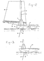
- the sailing craft 1 comprises a hull composed of two hull parts 2 and 3.
- a steering box 4 accommodating the steering mechanism to be discussed hereinafter and also receiving the mast 5.
- a junction 6 which together with the hull part 3 constitutes the position or seat 7 to be taken by the sailor.
- the head 8 of the mast 5 is connected to a sail 10 which may be hoisted or lowered by means of a halyard 9 which halyard 9 may be fastened to the bottom of the mast 5 at 11.
- the lower edge of the sail preferably being isoscelles in outline is connected to a boom 12 to be described hereinafter.
- Sheets 13 and 14 are connected to the boom 12, said sheets being guided to seat 7 of the sailor by way of proper means, such as shackles 15, rollers 16 and belaying means 17.
- the side of the steering box 4 comprises two treadles 18 and 19 upon which a seated sailor places his feet for operating the steering mechanism to be discussed hereinafter.
- the hull part 2 is designed such that a skimming plane 20 is formed enclosing an angle a with respect to the surface of the water when the sailing craft and the water are quiet.
- this angle a is 15° though in general it will be between 10° and 20°.
- this angle is called the normative angle of inclination.
- Dependent on the force of the wind during sailing the sailing craft (when viewed in Fig. 1) will heel over to the left, whereby the hull part 3 will be lifted more or less out of the water - to a certain extent dependent on this heel over - causing the skimming plane 20 to acquire more and more the most favourable position for skimming.
- the most favourable position of the sail 10 is reached at a heel over between 10° and 20°.
- the sailing craft is provided with rudder means 21, the axis of rotation of which is perpendicular to the skimming plane 20, which rudder means are equal distance at either side of the centre cross-plane.
- the rudder means 21 are in the shape of a blade.
- the said axis of rotation is also the axis of symmetry of said blade-like means 21.
- the blade-like means furthermore function as keel surfaces for controlling the leeward drift of the sailing craft.
- Fig. 2 With reference to Fig. 2 there is shown a sailing craft having two hull parts 2 and 3. However it is also possible to construct the sailing craft such that she will have only one hull part 23 like shown in Fig. 3.
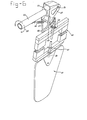
- the lower edge of the sail 10 is connected to a boom 12.
- This boom 12 consists of a spar 24 the ends of which are provided with boom attachments 25, 26 to which the lowermost tips 27, 28 of the sail are belayed.
- One of the boom attachments 25 is movable along the boom, whereas the other one 26 is fixedly belayed.
- the edging 29 of the sail may be strained or slackened by means of the edging strainer 30.
- the sheets 13, 14 are connected to boom shackles 31, 32 which boom shackles on their turn are fastened to the boom attachments 25, 26 and which are adjustable thereon in the positions a to f, inclusive, the position a being close to the point where the sail 10 is fastened to the boom attachments 25, 26.
- 'a' is the light wind position and 'f' is the strong wind position.
- This sailing craft design does not allow for tailoring and/or straining the sail in accordance with the ideal profile (wherein the strongest convexity is at ⁇ 1/3 to the front) because upon' changing the sailing direction fore and aft are reversed so that it is necessary to install this system.
- the operation is based on the angular differential between boom shackle and sheet between the fixedly belayed sheet 14 and the handling sheet 13.
- the trimming line 35 Due to the vertical position of the fixedly belayed sheet 14 between the deck and boom, the trimming line 35 is tautened by means of the lever action of trimming plate 34 whereby the sail is pulled at point 36. (Because the other end of the trimming line is fastened to the boom attachment where the sail is attached.) The force exerted on the sail by the trimming line 35 at point 36 is transferred to the back part of the edging of the sail by means of the sailing lath 37, thus causing the ideal profile to be formed. Due to the relatively more horizontal position of the handling sheet the trimming line 38 is slackened, whereby the point 39 on the sail may freely swing outward.
- keel blades functioning at the same time as rudder means: These means are operated by the sailor by working the treadles 18, 19.
- the rudder-keel blades 21 are of symmetric design with respect to the rotation axis 39 and as will be evident from Fig. 7 the rudder-keel blades 21 are arranged at equal distances from the centre cross-plane at either side thereof. The whole may be lowered through a slot in the skimming plane of the vessel whereby the frame 40 will come to rest in grooves in the hull 2 (not shown).
- the frame 40 includes a framing part in which the shaft 39 is rotatably mounted in bearings 41 and 42. At the top this shaft has been coupled to the hollow shaft 43 by means of a transmission to be described below said hollow shaft furthermore being connected to the treadles 18, 19.
- the treadles 18, 19 are mounted in openings 44 in the wall 45 of the steering box 4 facing the sailor as is shown in Fig. 5, the arrangement being such, that the sailor by means of hit feet may rotate the treadles about the axis 46 of the bearing means 44, 48 (in Fig. 5) arranged within the steering box 4.
- the shaft 43 is rotatably mounted in the said bearing means 47, 48 (in Fig. 5) which may be of a design known per se.
- helm 49 To the top of the shaft 39 there is connected a "helm" 49, the free end 50 of which is connected to the top of a V-shaped means 51, the latter being connected to a box shaped means 52 by means of welds or otherwise.
- the shaft 43 extends to nearby said means 52 and is provided at this extremity of a means 53 arranged within the box shaped means .52.
- the two last mentioned means 52 and 53 are hingedly connected to each other by means of a spindle 54. If now the shaft 43 is rotated in the direction of the arrow 55 (Fig. 6) the free end 50 of the helm 49, as viewed in Fig. 6, is turned to the left and consequently also the rudder blade 21.
- the means 52 is forced to hinge downward about the spindle 54 because the helm 49 may only be swung in a plane perpendicular to the shaft 39. This movement of the means 52 with respect to the means 53 occurs until the top part of the means 52 will come in engagement with the means 53.
- the spring 56 is a homing spring endeavouring to reset the means 52 and 53 in the starting position thereof like indicated in Fig. 6.
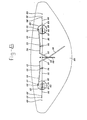
- exemplary embodiment to be described hereinafter and shown in Figs. 8, 9 and 10 is of simple design and better controllable while there is also provided a certain coupling between the different operations.
- each one of the rudder blades 101 - a cylindrical box 102 which is rotatably mounted in a cylindrical opening 103 extending through the entire height of the whole of the sailing craft.
- the rudder blade 101 is connected to the box 102.
- a rudder reversal ring 104 is mounted at the top of the box 102.
- In the top of the box 102 there is provided a slot 105 in which the top of the rudder blade 101 may be moved back and forth as will be described hereinafter.
- a rudder reversal line 106 for coupling the two reversal rings 104, said rudder reversal line 106 extending from the opposite sides of the reversal rings 104 to a slide 107 adapted to run on a rail 108.
- This slide 107 is connected to the end of a not shown sheet running through the loop 109 to the relative tip of the not shown sail (vide Fig. 1 sheet 13 or 14, respectively).
- a rod system comprising a rod 110 connected at its one end 111 to an eccentric point 112 hingedly mounted to the box and at its other end 113 to the junction of the arms 114, 115 of a bell crank lever 116, the latter being hingedly connected to the deck 100 by way of its arm 114 and being hingedly connected at its other end to a straight rod 117 which together with its other end 118 is hingedly connected to a helm 119.
- the last mentioned hinge joint 118 is slidably mounted in a straight guide 120 provided in the centre cross plane of the sailing craft on the deck 100. This design has the special advantage that the rudder blades may be adjusted at any desired level and may be pulled up quickly.
- Figs. 8 and 9 represent the sailing craft while sailing in a straight course to the left hand side of the drawing.
- the rudder blades 101 For sailing to the right hand side the rudder blades 101 have to be swung over an angle a of about 20° at maximum.
- the rudder blades When turning the rudder blades have to be pivoted so that their axis 121 moves from one position to the other, that is to say corresponding to the changed position of the sail.
- the position of the sail has to be changed.
- the sheets 13, 14 connected to the slides 107 have to be operated whereby swinging from the position shown in Fig. 9 to the position swung over an angle a occurs simultaneously.
- the material usd for the several parts is corrosion resistant, preferably plastic material either reinforced or not or a metal coated with plastic material. Self lubricating materials or water lubricated materials are preferred therein.
- the present invention provides a new type of sailing craft utilizing most favourably the possibilities created by the application of the normative angle of inclination.
Landscapes
- Engineering & Computer Science (AREA)
- Combustion & Propulsion (AREA)
- Ocean & Marine Engineering (AREA)
- Mechanical Engineering (AREA)
- Chemical & Material Sciences (AREA)
- Fluid Mechanics (AREA)
- Physics & Mathematics (AREA)
- Sustainable Energy (AREA)
- Sustainable Development (AREA)
- Life Sciences & Earth Sciences (AREA)
- Toys (AREA)
- Organic Low-Molecular-Weight Compounds And Preparation Thereof (AREA)
- Lubricants (AREA)
- Diaphragms For Electromechanical Transducers (AREA)
Claims (7)
Priority Applications (1)
| Application Number | Priority Date | Filing Date | Title |
|---|---|---|---|
| AT81201057T ATE11389T1 (de) | 1980-09-30 | 1981-09-21 | Segelboot. |
Applications Claiming Priority (2)
| Application Number | Priority Date | Filing Date | Title |
|---|---|---|---|
| NL8005425 | 1980-09-30 | ||
| NL8005425A NL8005425A (nl) | 1980-09-30 | 1980-09-30 | Zeilvaartuig. |
Publications (2)
| Publication Number | Publication Date |
|---|---|
| EP0049018A1 EP0049018A1 (de) | 1982-04-07 |
| EP0049018B1 true EP0049018B1 (de) | 1985-01-23 |
Family
ID=19835950
Family Applications (1)
| Application Number | Title | Priority Date | Filing Date |
|---|---|---|---|
| EP81201057A Expired EP0049018B1 (de) | 1980-09-30 | 1981-09-21 | Segelboot |
Country Status (6)
| Country | Link |
|---|---|
| US (1) | US4503795A (de) |
| EP (1) | EP0049018B1 (de) |
| AT (1) | ATE11389T1 (de) |
| AU (1) | AU7576881A (de) |
| DE (1) | DE3168508D1 (de) |
| NL (1) | NL8005425A (de) |
Families Citing this family (11)
| Publication number | Priority date | Publication date | Assignee | Title |
|---|---|---|---|---|
| GB2128153B (en) * | 1982-09-25 | 1986-06-04 | Frank Robert Goodman | Sailboats |
| DE3540174A1 (de) * | 1985-11-13 | 1987-05-21 | Werner Dipl Ing Schoenenberg | Segelanordnung fuer fahrzeuge |
| US4766830A (en) * | 1986-08-15 | 1988-08-30 | Daniel Kunz | Boat, especially a catamaran, with large deck space and collapsible frame |
| US4819574A (en) * | 1987-04-21 | 1989-04-11 | Westerman Charles W | Rudderless sailboat |
| WO1989011994A1 (en) * | 1988-05-31 | 1989-12-14 | Sarrinen Pty. Ltd. | Sailing vessels |
| FR2632600A1 (fr) * | 1988-06-14 | 1989-12-15 | Roche Kerandraon Oliver | Bateaux rapides type " prao " de construction simplifiee |
| FR2686566B1 (fr) * | 1992-01-24 | 1994-10-07 | John Kingston Pizzey | Voilier. |
| USD370885S (en) | 1995-05-02 | 1996-06-18 | Brock William D | Sailboat |
| US5957071A (en) * | 1996-07-01 | 1999-09-28 | Brock; William D. | Sailboat |
| US6202582B1 (en) | 1998-12-24 | 2001-03-20 | Jerome Risley | Asymmetrically shaped sailboat |
| US7637221B1 (en) | 2009-02-27 | 2009-12-29 | Sinden Frank W | Sailboat |
Family Cites Families (15)
| Publication number | Priority date | Publication date | Assignee | Title |
|---|---|---|---|---|
| US95442A (en) * | 1869-10-05 | Improvement in bands for booms and gaffs | ||
| US92539A (en) * | 1869-07-13 | Improved otjthattl for boomis | ||
| US1295732A (en) * | 1918-04-10 | 1919-02-25 | John Sisson Graham | Steering apparatus for vessels. |
| US2917754A (en) * | 1955-12-27 | 1959-12-22 | Charles F Gunderson | Catamarans |
| US3173395A (en) * | 1963-04-18 | 1965-03-16 | Price Ranch | Double ended sailboat |
| US3223065A (en) * | 1964-05-04 | 1965-12-14 | Jr Aubrey Bennett Wilson | Sailboat |
| US3307511A (en) * | 1965-10-18 | 1967-03-07 | Merlin S Chapman | Catamarans |
| US3304899A (en) * | 1965-10-22 | 1967-02-21 | Weatherly Goodhue | Reversible sailing vessel |
| US3336890A (en) * | 1966-02-16 | 1967-08-22 | Andre J M Laurent | Keel structure |
| US3571831A (en) * | 1968-10-04 | 1971-03-23 | Elmer W Conklin | Float |
| US3585955A (en) * | 1969-04-10 | 1971-06-22 | Richard T Cella | Asymmetric catamaran |
| US4054100A (en) * | 1975-06-05 | 1977-10-18 | R. Lynn Rineman | Sport sailboat |
| US3985090A (en) * | 1975-06-05 | 1976-10-12 | Harold J. Rineman | Sport boat |
| FR2337077A1 (fr) * | 1975-12-29 | 1977-07-29 | Dauphin Francis | Greement mobile pour catamaran |
| US4061099A (en) * | 1977-02-23 | 1977-12-06 | Gregory Edward Cook | Outrigger sailboat |
-
1980
- 1980-09-30 NL NL8005425A patent/NL8005425A/nl not_active Application Discontinuation
-
1981
- 1981-09-21 AT AT81201057T patent/ATE11389T1/de not_active IP Right Cessation
- 1981-09-21 EP EP81201057A patent/EP0049018B1/de not_active Expired
- 1981-09-21 DE DE8181201057T patent/DE3168508D1/de not_active Expired
- 1981-09-29 AU AU75768/81A patent/AU7576881A/en not_active Abandoned
-
1984
- 1984-02-13 US US06/578,609 patent/US4503795A/en not_active Expired - Fee Related
Also Published As
| Publication number | Publication date |
|---|---|
| NL8005425A (nl) | 1982-04-16 |
| DE3168508D1 (en) | 1985-03-07 |
| ATE11389T1 (de) | 1985-02-15 |
| AU7576881A (en) | 1982-04-08 |
| EP0049018A1 (de) | 1982-04-07 |
| US4503795A (en) | 1985-03-12 |
Similar Documents
| Publication | Publication Date | Title |
|---|---|---|
| US3972300A (en) | Sailing craft | |
| US3802366A (en) | Hydrofoil sailboat | |
| US3580203A (en) | Sailboat | |
| US6910434B2 (en) | Control device for steering kite on a boat | |
| EP0049018B1 (de) | Segelboot | |
| US3858542A (en) | Directing sail | |
| US20130247807A1 (en) | Anti-Heeling Apparatus for Sailboats | |
| US4345535A (en) | Sailboat trimming and stabilizing system | |
| US20150274266A1 (en) | High-performance planing monohull sailboat with heeling control | |
| US3373710A (en) | Hydrofoil boat | |
| US4273060A (en) | Sailing vessel | |
| US4843987A (en) | Heel counteracting airfoil | |
| GB2085387A (en) | Sails | |
| US3986473A (en) | Removable boat steering and sail propulsion unit | |
| EP0245263A1 (de) | Takelage für windgetriebenes fahrzeug | |
| CA2185432A1 (en) | A yacht | |
| EP0079949B1 (de) | Wind-flügelsystem | |
| US4377124A (en) | Sailboat with an inclinable keel board | |
| US6386130B1 (en) | Control systems for sailing vessels | |
| EP0695684A1 (de) | Segelanordnung für ein Segelboot | |
| US4803938A (en) | Rotor powered sailboat | |
| EP0075208A2 (de) | Segeltakelage für Wasserfahrzeuge | |
| CA2229033A1 (en) | Method for sailing a boat, and sailing vessel | |
| US4706590A (en) | Deck mounted lateral mast rake adjuster | |
| US5816180A (en) | Rotating rig |
Legal Events
| Date | Code | Title | Description |
|---|---|---|---|
| PUAI | Public reference made under article 153(3) epc to a published international application that has entered the european phase |
Free format text: ORIGINAL CODE: 0009012 |
|
| AK | Designated contracting states |
Designated state(s): AT BE CH DE FR GB IT LU NL SE |
|
| 17P | Request for examination filed |
Effective date: 19821001 |
|
| ITF | It: translation for a ep patent filed | ||
| GRAA | (expected) grant |
Free format text: ORIGINAL CODE: 0009210 |
|
| AK | Designated contracting states |
Designated state(s): AT BE CH DE FR GB IT LI LU NL SE |
|
| PG25 | Lapsed in a contracting state [announced via postgrant information from national office to epo] |
Ref country code: NL Effective date: 19850123 Ref country code: BE Effective date: 19850123 |
|
| REF | Corresponds to: |
Ref document number: 11389 Country of ref document: AT Date of ref document: 19850215 Kind code of ref document: T |
|
| REF | Corresponds to: |
Ref document number: 3168508 Country of ref document: DE Date of ref document: 19850307 |
|
| ET | Fr: translation filed | ||
| NLV1 | Nl: lapsed or annulled due to failure to fulfill the requirements of art. 29p and 29m of the patents act | ||
| PG25 | Lapsed in a contracting state [announced via postgrant information from national office to epo] |
Ref country code: AT Effective date: 19850921 |
|
| PG25 | Lapsed in a contracting state [announced via postgrant information from national office to epo] |
Ref country code: SE Effective date: 19850922 |
|
| PG25 | Lapsed in a contracting state [announced via postgrant information from national office to epo] |
Ref country code: LU Free format text: LAPSE BECAUSE OF NON-PAYMENT OF DUE FEES Effective date: 19850930 |
|
| PLBE | No opposition filed within time limit |
Free format text: ORIGINAL CODE: 0009261 |
|
| STAA | Information on the status of an ep patent application or granted ep patent |
Free format text: STATUS: NO OPPOSITION FILED WITHIN TIME LIMIT |
|
| 26N | No opposition filed | ||
| GBPC | Gb: european patent ceased through non-payment of renewal fee | ||
| PG25 | Lapsed in a contracting state [announced via postgrant information from national office to epo] |
Ref country code: GB Effective date: 19881118 |
|
| PGFP | Annual fee paid to national office [announced via postgrant information from national office to epo] |
Ref country code: DE Payment date: 19890131 Year of fee payment: 8 |
|
| PGFP | Annual fee paid to national office [announced via postgrant information from national office to epo] |
Ref country code: FR Payment date: 19890307 Year of fee payment: 8 Ref country code: CH Payment date: 19890307 Year of fee payment: 8 |
|
| PG25 | Lapsed in a contracting state [announced via postgrant information from national office to epo] |
Ref country code: LI Effective date: 19890930 Ref country code: CH Effective date: 19890930 |
|
| PG25 | Lapsed in a contracting state [announced via postgrant information from national office to epo] |
Ref country code: FR Effective date: 19900531 |
|
| REG | Reference to a national code |
Ref country code: CH Ref legal event code: PL |
|
| PG25 | Lapsed in a contracting state [announced via postgrant information from national office to epo] |
Ref country code: DE Effective date: 19900601 |
|
| REG | Reference to a national code |
Ref country code: FR Ref legal event code: ST |
|
| EUG | Se: european patent has lapsed |
Ref document number: 81201057.7 Effective date: 19860729 |