EP0049062A2 - Etalonnage du dispositif de pesage d'un appareil d'alimentation gravimétrique en charbon - Google Patents
Etalonnage du dispositif de pesage d'un appareil d'alimentation gravimétrique en charbon Download PDFInfo
- Publication number
- EP0049062A2 EP0049062A2 EP81304103A EP81304103A EP0049062A2 EP 0049062 A2 EP0049062 A2 EP 0049062A2 EP 81304103 A EP81304103 A EP 81304103A EP 81304103 A EP81304103 A EP 81304103A EP 0049062 A2 EP0049062 A2 EP 0049062A2
- Authority
- EP
- European Patent Office
- Prior art keywords
- weight
- shaft
- calibrating
- sensing mechanism
- axis
- Prior art date
- Legal status (The legal status is an assumption and is not a legal conclusion. Google has not performed a legal analysis and makes no representation as to the accuracy of the status listed.)
- Granted
Links
- 239000003245 coal Substances 0.000 title abstract description 30
- 230000007246 mechanism Effects 0.000 claims abstract description 35
- 239000000463 material Substances 0.000 claims abstract description 6
- 239000011236 particulate material Substances 0.000 claims abstract description 4
- 238000005303 weighing Methods 0.000 claims description 27
- 230000000712 assembly Effects 0.000 claims description 11
- 238000000429 assembly Methods 0.000 claims description 11
- 239000002245 particle Substances 0.000 description 4
- 229910000831 Steel Inorganic materials 0.000 description 2
- 238000002485 combustion reaction Methods 0.000 description 2
- 239000010959 steel Substances 0.000 description 2
- 241000273930 Brevoortia tyrannus Species 0.000 description 1
- 208000037063 Thinness Diseases 0.000 description 1
- 230000007613 environmental effect Effects 0.000 description 1
- 238000010304 firing Methods 0.000 description 1
- 230000005484 gravity Effects 0.000 description 1
- 230000001788 irregular Effects 0.000 description 1
- 238000000034 method Methods 0.000 description 1
- 230000032258 transport Effects 0.000 description 1
- 206010048828 underweight Diseases 0.000 description 1
- 238000011144 upstream manufacturing Methods 0.000 description 1
Images


Classifications
-
- G—PHYSICS
- G01—MEASURING; TESTING
- G01G—WEIGHING
- G01G23/00—Auxiliary devices for weighing apparatus
- G01G23/01—Testing or calibrating of weighing apparatus
- G01G23/012—Testing or calibrating of weighing apparatus with load cells comprising in-build calibration weights
-
- F—MECHANICAL ENGINEERING; LIGHTING; HEATING; WEAPONS; BLASTING
- F23—COMBUSTION APPARATUS; COMBUSTION PROCESSES
- F23K—FEEDING FUEL TO COMBUSTION APPARATUS
- F23K3/00—Feeding or distributing of lump or pulverulent fuel to combustion apparatus
- F23K3/16—Over-feed arrangements
-
- G—PHYSICS
- G01—MEASURING; TESTING
- G01G—WEIGHING
- G01G11/00—Apparatus for weighing a continuous stream of material during flow; Conveyor belt weighers
- G01G11/08—Apparatus for weighing a continuous stream of material during flow; Conveyor belt weighers having means for controlling the rate of feed or discharge
- G01G11/10—Apparatus for weighing a continuous stream of material during flow; Conveyor belt weighers having means for controlling the rate of feed or discharge by controlling the height of the material on the belt
Definitions
- This invention relates to a weight-senser calibration device, having application in for example, apparatus for feeding particulate material, such as coal particles, to be burned in a coal combustion system in an electrical power plant in which the coal is fed at a controlled rate to a furnace or other component.
- apparatus may comprise a gravimetric feeder whose rate of feed is monitored and automatically controlled.
- coal is fed downwardly by gravity from overhead hoppers or bunkers to pulverizers or other power plant components such as boiler stokers or cyclone burners.
- the feed rate may be controlled by a gravimetric feeder such as that shown and described in U.S. Patent No. 3,187,944.
- the gravimetric feeder receives the particulate coal in the form of a continuous stream in a fixed flow path, and delivers the coal at a controlled rate as free-falling or separately flowing particles.
- the rate of discharge by weight is controllable to achieve accurate control of the fuel-air ratio.
- a feeder of this type enables the coal flow to be divided equally among Several firing units of a single boiler.
- Such feeders utilize a horizontal conveyor located within a sealed enclosure and adapted to contain gas at a pressure higher than ambient atmospheric air pressure.
- the conveyor includes an endless belt with an upper span or run that receives coal through an inlet in the enclosure in the form of a column from the hopper.
- the upper belt run transports a layer of the coal at a level controlled by an adjustable leveling bar or valve across a weighing span of predetermined length, which weighing span is supported by one or more rollers, one roller being a weighing roller.
- the weighing roller thus carries a predetermined portion of the weight of coal on the weighing span and the weight carried thereby is sensed by a weight-sensing mechanism including, for example, load cells of the type readily obtainable from commercial sources. If the weight sensed varies from that desired, then the weighing mechanism automatically moves the leveling bar to adjust the depth (and thus the weight) of coal transported on the belt.
- the equipment have provision for applying a test load to the mechanism at frequent intervals with a minimum of effort in order to check calibration and make any necessary adjustments.
- a device for selectively applying a test load to a weight-sensing mechanism that includes means for continuously sensing the weight of a variable operating load and means for generating a signal representative of the weight sensed by said means, said device comprisinga calibrating weight, a control shaft located above said weight sensing mechanism, at least one vertical support rod operatively connected to said control shaft at its upper end and connected to said calibrating weight at its lower end, and means for rotating said shaft about its axis between a first position wherein said calibrating weight is supported by said vertical rod and a second position wherein the weight of said calibrating weight is transferred to said weight sensing mechanism.
- a device for selectively applying a test load to a weight-sensing mechanism in an enclosed conveyor unit for feeding material at a controlled rate said weight-sensing mechanism including means for continuously sensing the weight of a variable quantity of material being conveyed through a predetermined reference zone and load cell means for generating a voltage signal representative of the weight sensed by said means, said device comprising a calibrating weight, a control shaft journaled in said conveyor unit and having its axis transverse to the direction of feed, a pair of circular eccentric members mounted on said shaft at spaced locations from and coaxial with one another on opposite ends of said shaft and with their common axis of eccentricity offset from the axis of said shaft, a pair of vertical support rods one being operatively connected to one of said eccentric members and the other being operatively connected to the other of said eccentric members, said calibrating weight being adapted to be supported by and between said support rods, and means for rotating said shaft between a
- a gravimetric feeder having a belt conveyor for conveying particulate material to a delivery zone, said conveyor embodying a weighing span supported by a plurality of rollers, one of said rollers being a weighing roller, said weighing roller being supported by a weight sensing mechanism embodying load cells adapted to generate a signal representative of the weight supported by said weighing roller, said feeder also having means for calibrating said weight sensing mechanism comprising a calibrating weight and manually controllable means for selectively supporting said calibrating weight from said load cells when it is desired to calibrate said weighing system and for supporting said calibrating weight independently of said load cells during normal operation of said feeder.
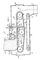
- FIGS. 1 and 2 there is shown a gravimetric coal feeder A adapted to receive a column 10 of particulate coal through an inlet conduit 11, from a hopper 12.
- the apparatus A feeds the coal from the column 10 at a controlled rate of flow to a discharge chute or conduit 13 at the right-hand end as viewed in FIG. 1.
- the coal is delivered to the discharge chute as free-falling or separately flowing particles and the rate of flow is controllable in terms of the weight of the material being discharged.
- the apparatus A includes an elongated housing 14 with an upwardly facing inlet 11 having an annular flange 15 at the top for use in connecting the inlet 11 to the outlet of the hopper 12.
- the housing 14 also has a downwardly facing outlet 16 with an annular flange 17 at its lower end for use in bolting the outlet 16 to the discharge chute 13.
- the housing 14 may be formed, for example, of steel of suitable strength. Access doors 18 and 19 are located at the opposite ends of the housing 14 to permit access to the interior of the feeder A.
- a feeder conveyor generally indicated by the numeral 20 is located within the housing and combines an endless belt 21 formed of molded, fabric-reinforced rubber that passes between a power-driven head pulley 22 and a tail pulley 23. Tension in the belt 21 is maintained by a tension roller 24.
- the belt 21 has a central V-shaped rib 25 formed in the inside thereof that seats in V-shaped grooves in the head pulley 22, tail pulley 23 and tension roller 24. Also, the belt 21 has projecting curbs 26 and 27 formed on opposite edges thereof to guide the coal carried thereon and to minimize overflow of the coal at the sides of the- belt.
- the head pulley 22 is driven by a variable-speed motor (not shown) and the speed of the output shaft of the motor is normally controlled by an electrical voltage furnished by combustion control means for the furnace to which coal is supplied by the feeder.
- a layer of coal is carried from left to right as viewed in FIG. 1 from the bottom of the column 10 across the upper span 28 of the endless belt 21 to an exit or drop-off zone 29 at the right-hand end of the span 28.
- the gravimetric feed system 30 comprises three parallel, equally spaced apart rollers, including a pair of weigh span rollers 31 and 32 and a weighing roller 33 located between the rollers 31 and 32.
- the weighing roller 33 has a central shaft 33a journaled in bearing assemblies 34 at its opposite ends.
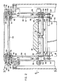
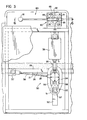
- the roller 33 and bearing assemblies 34 are supported by a pair of weighing roller support assemblies 35 located on opposite sides of the upper span 28 of the belt 21 (FIGS. 2 and 3).
- the bearing assemblies 34 are connected to one end of an arm or link 36 extending generally horizontally and pivoted at its opposite end in a bracket 37.
- the arm 36 serves to locate the weighing roller 33 in its desired longitudinal position relative to the upper span 28. It will be noted that other components of the gravimetric control system are shown diagrammatically in FIG. 1.
- the upper ends of the weighing roller support assemblies 35 are connected to load cells 38 and 39 which are adapted to sense either an overweight or an underweight condition with reference to the weight of the coal in the weighing span of the upper span 28 of the belt 21 between the weigh span rollers 31 and 32.
- the load cells 38 and 39 have an output voltage that is used to control an electric motor 41 (FIG. 1).
- the motor 41 turns a screw operatively connected to an arm 43 of a crank that swings about a pivot 44.
- a leveling bar 45 carried on an arm 46 of the crank substantially perpendicular to the arm 43 is positioned at the upstream end of the column 10 of coal in the inlet 11 and regulates, through its raising and lowering movement, the level (and thus the-weight) of the layer of coal carried from the column by the upper span 28 of the endless belt 21.
- the gravimetric control system which is illustrated generally in schematic form in FIG. 1 is shown and described in more detail in U.S. Patent No. 3,187,944.
- a cleanout conveyor (FIG. 1) is provided and mounted with its lower span immediately above a floor section that extends all the way to the outlet 16 of the housing 14.
- the cleanout conveyor extends horizontally-beneath the conveyor 20 to the outlet 16 and comprises a pair of parallel chains 47 extending between pairs of parallel, power-driven head sprockets 48 and tail sprockets 49. Certain links of the chains 47 carry transversely extending, spaced parallel cleanout bars that move across and contact the floor to move accumulated spilled coal and discharge it into the discharge chute 13.
- a test load in the form of a calibrating weight 50 is provided.
- This load may be applied to the weighing mechanism when the feeder A is not in operation:and when there is no coal carried on the upper span 28 of the belt 21.
- the calibrating weight 50 is a flat steel plate with its top edge beveled on both sides to a point so that coal particles or other debris cannot accumulate thereon to change the weight to be applied for calibration purposes.
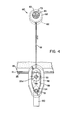
- the calibrating weight 50 is normally carried during operation of the feeder A in an independently supported condition as illustrated in FIGS. 1, 2, 3 and 4 (solid lines), but it may be lowered by the mechanism of the invention to a calibrating position wherein its weight is transferred from its independently supported condition to the load cells 38 and 39 for the purpose of calibrating the gravimetric feed control system 30.
- the calibrating weight 50 has laterally extending carrier pins 51 and 52 at its opposite ends that are used to support the weight in both of its positions.
- Each of the pins 51 and 52 has an annular outer groove 53 and an annular inner groove 54, the grooves having a generally V-shaped cross section.
- a pair of hanger loops 55 attached to the bearing assemblies 34 engage the pins 51 and 52 and support the calibrating weight 50 when it is moved to its calibrating position so that the weight of the calibrating weight 50 is applied through the bearing assemblies 34 and weighing roller support assemblies 35 to the load cells 38 and 39.
- the carrier pins 51 and 52 are engaged and supported by a pair of hanger loops 56 so that the load cells 38 and 39 are relieved of the load of the calibrating weight 50.
- the interior edges 57 of the opening in the hanger loops 55 are provided with a knife-edge shape that engages in the outer annular grooves 53.
- the interior edges 58 of the opening in the hanger loops 56 are provided with a knife-edge shape that engages in the inner annular grooves 54 of the pins 51 and 52.
- the knife-edge shaped edges 58 of the hanger loops 56 engage in annular grooves 59 at opposite sides of the weighing roll 33 in order to restrain lateral swinging movement of the calibrating weight 50.
- the openings in the hanger loops 55 are circular and have a diameter substantially larger than the diameter of the carrier pins 51 and 52.
- the openings in the hanger loops 56 have an elongated irregular shape as best shown in FIG. 4.
- the hanger loops 56 are attached to operating mechanisms 60, best shown in FIGS. 3, 4 and 6, by vertical hanger rods 61, best shown in FIGS. 2 and 4.
- the upper ends of the hanger rods 61 have connecting heads 62 that cooperate with the respective supporting and operating mechanism 60 to raise and lower the calibrating weight 50 between its two positions.
- the lifting and lowering function is accomplished by the operating mechanism 60 located at the top of the feeder A and which includes a laterally extending shaft 63 with retaining flanges 64 welded at each end.
- a pair of hubs 65 and 66 are fixed to the shaft 63 at its opposite ends adjacent and keyed to the respective retaining flanges 64.
- the hubs 65 and 66 are secured against lateral movement by screws 67 and 68 which urge the respective hubs 65 and 66 against the retaining flanges 64.
- the hubs and shaft assembly are adapted for rotary movement, the hubs 65 and 66 being journaled in bearing assemblies 69 and 70 mounted in bearing blocks 71 and 72 secured to the housing 14.
- the hubs 65 and 66 have inwardly extending, eccentric circular cams 73 and 74 on their inner ends,which.engage the circular openings in the connecting heads 62. t
- the movement of the operating mechanism 60 in order to lift and lower the calibrating weight 50 is accomplished by means of an operating lever 80 having a handle 81 and a pivot block 82.
- the pivot block 82 is received in a lateral slot 83 in the outer end of the hub 65 and also a portion thereof is normally received in a lateral slot in the bearing block 71.
- the operating lever 80 is mounted for pivotal movement by a pivot pin 85 which extends between opposite sides of the slot 83 so that the operating lever is capable of limited sideways (as opposed to rotary) movement as indicated by the arrows and angularly disposed dashed line positions shown in FIG. 6.
- the inner end of the pivot block 82 is engaged by a helical spring 86 which urges the lever 80 to its radially extending position with the pivot block 82 seated in both the slot 83 in the hub 65 and the slot 84 in the bearing block 71 to lock the lever 30 against rotary movement.
- the spring 86 is seated in a longitudinally extending recess 87 in the hub 65.
- This test load applying procedure is accomplished when the movement of the conveyor has been halted and when there is no pulverized coal carried on the conveyor belt 21 so that the only load being sensed in addition to the weight of the weighing span of the conveyor belt is that of the calibrating weight 50.
- the load cells 38 and 39 send a voltage signal to the feed rate control system so that the system 30 can be calibrated to achieve the proper adjustment.
Landscapes
- Engineering & Computer Science (AREA)
- Physics & Mathematics (AREA)
- General Physics & Mathematics (AREA)
- Chemical & Material Sciences (AREA)
- Combustion & Propulsion (AREA)
- Mechanical Engineering (AREA)
- General Engineering & Computer Science (AREA)
- Weight Measurement For Supplying Or Discharging Of Specified Amounts Of Material (AREA)
Applications Claiming Priority (2)
| Application Number | Priority Date | Filing Date | Title |
|---|---|---|---|
| US190963 | 1980-09-26 | ||
| US06/190,963 US4353427A (en) | 1980-09-26 | 1980-09-26 | Weight-sensor calibration for gravimetric coal feeder |
Publications (3)
| Publication Number | Publication Date |
|---|---|
| EP0049062A2 true EP0049062A2 (fr) | 1982-04-07 |
| EP0049062A3 EP0049062A3 (en) | 1982-09-22 |
| EP0049062B1 EP0049062B1 (fr) | 1985-02-06 |
Family
ID=22703516
Family Applications (1)
| Application Number | Title | Priority Date | Filing Date |
|---|---|---|---|
| EP81304103A Expired EP0049062B1 (fr) | 1980-09-26 | 1981-09-08 | Etalonnage du dispositif de pesage d'un appareil d'alimentation gravimétrique en charbon |
Country Status (8)
| Country | Link |
|---|---|
| US (1) | US4353427A (fr) |
| EP (1) | EP0049062B1 (fr) |
| JP (1) | JPS5776418A (fr) |
| AU (1) | AU546602B2 (fr) |
| CA (1) | CA1163113A (fr) |
| DE (1) | DE3168796D1 (fr) |
| ES (1) | ES8301363A1 (fr) |
| ZA (1) | ZA815506B (fr) |
Cited By (7)
| Publication number | Priority date | Publication date | Assignee | Title |
|---|---|---|---|---|
| US4430963A (en) * | 1982-12-03 | 1984-02-14 | General Signal | System for generating dry coal weight signal for coal feeder and control system based thereon |
| US4528848A (en) * | 1982-05-08 | 1985-07-16 | Pfister Gmbh | Device for the continuous gravimetric metering and pneumatic conveyance of pourable material |
| FR2585466A1 (fr) * | 1985-07-01 | 1987-01-30 | Tobacco Res & Dev | Dispositif a courroie de pesage |
| CN100445706C (zh) * | 2006-12-27 | 2008-12-24 | 山西新元自动化仪表有限公司 | 无测速传感器皮带秤 |
| CN101089565B (zh) * | 2006-06-13 | 2010-09-29 | 上海新拓电力设备有限公司 | 一种给煤机定度探头的配对装置及配对方法 |
| CN106044265A (zh) * | 2016-06-22 | 2016-10-26 | 杭州市萧山区高级技工学校 | 一种井下煤仓称重系统 |
| IT201600129870A1 (it) * | 2016-12-22 | 2018-06-22 | Tecnofill S R L | Dosatore di prodotti alimentari, in particolare in forma cubettata, sminuzzata o sfilacciata. |
Families Citing this family (26)
| Publication number | Priority date | Publication date | Assignee | Title |
|---|---|---|---|---|
| US4480705A (en) * | 1982-08-05 | 1984-11-06 | Rexnord Inc. | Platform calibration factor for conveyor inclination angle |
| US4846081A (en) * | 1987-04-08 | 1989-07-11 | General Signal Corporation | Calorimetry system |
| US4895081A (en) * | 1987-04-08 | 1990-01-23 | General Signal Corporation | Gravimetric feeder, especially adapted for use in a calorimetry system |
| US4893315A (en) * | 1987-04-08 | 1990-01-09 | General Signal Corporation | Calorimetry system |
| US4809190A (en) * | 1987-04-08 | 1989-02-28 | General Signal Corporation | Calorimetry system |
| US5686653A (en) * | 1996-05-09 | 1997-11-11 | General Signal Corporation | System for checking the calibration of gravimetric feeders and belt scales |
| US5784974A (en) * | 1997-04-22 | 1998-07-28 | General Signal Corporation | System for improving fuel feed control of volumetric coal feeders |
| KR100406417B1 (ko) * | 1999-12-20 | 2003-11-19 | 주식회사 포스코 | 원료하역기 호퍼 중량검출장치 및 방법 |
| DE60004647T2 (de) * | 2000-06-09 | 2004-06-17 | Asnaesvaerket I/S (Division Vest Service) | Kohlenförderer |
| US7695535B2 (en) * | 2001-10-10 | 2010-04-13 | River Basin Energy, Inc. | Process for in-situ passivation of partially-dried coal |
| US8197561B2 (en) | 2001-10-10 | 2012-06-12 | River Basin Energy, Inc. | Process for drying coal |
| US7537622B2 (en) * | 2001-10-10 | 2009-05-26 | Fmi Newcoal, Inc. | Process for drying coal |
| US6818841B1 (en) | 2002-02-14 | 2004-11-16 | Mcdonald Ralph R. | Non-disruptive computer-controlled in-line conveyor flow weight calibration scale |
| CN201137953Y (zh) * | 2007-09-28 | 2008-10-22 | 江苏赛摩集团有限公司 | 高精度称重给煤机 |
| DE202009005883U1 (de) * | 2009-01-23 | 2010-03-11 | Futehally, Habib | Förderbandwaage |
| US8956426B2 (en) | 2010-04-20 | 2015-02-17 | River Basin Energy, Inc. | Method of drying biomass |
| US9057037B2 (en) | 2010-04-20 | 2015-06-16 | River Basin Energy, Inc. | Post torrefaction biomass pelletization |
| US8419501B2 (en) * | 2010-09-29 | 2013-04-16 | Stephen Engel | Apparatus for continuous weight monitoring of beehives |
| CN102012253B (zh) * | 2010-11-18 | 2012-07-04 | 赛摩电气股份有限公司 | 一种高精度皮带称重装置 |
| JP5904715B2 (ja) * | 2011-03-28 | 2016-04-20 | 大和製衡株式会社 | コンベヤスケール |
| CN103674195B (zh) * | 2013-12-04 | 2015-11-04 | 北京心觉工业设计有限责任公司 | 基于电子皮带秤的称重装置以及实现皮带高精度计量方法 |
| US12038319B2 (en) | 2017-09-28 | 2024-07-16 | Pelstar, Llc | Scale calibration device and method of use |
| CN111256904B (zh) * | 2018-11-30 | 2021-11-16 | 上海梅山钢铁股份有限公司 | 一种张力计在线校准装置及方法 |
| US11624648B2 (en) | 2019-07-09 | 2023-04-11 | Pelstar, Llc | Systems and methods for scale calibration |
| CN114136423B (zh) * | 2020-09-04 | 2024-12-03 | 梅特勒-托利多(常州)精密仪器有限公司 | 小物料精准称重计量的线性补偿装置及称重系统 |
| CN112278765A (zh) * | 2020-11-23 | 2021-01-29 | 西安热工研究院有限公司 | 一种具有独立称重模块的组合式埋刮板给煤机 |
Family Cites Families (9)
| Publication number | Priority date | Publication date | Assignee | Title |
|---|---|---|---|---|
| US2974518A (en) * | 1957-10-18 | 1961-03-14 | Consolidation Coal Co | Method and apparatus of calibrating a belt conveyer scale |
| US3187944A (en) * | 1962-10-09 | 1965-06-08 | Arthur J Stock | Gravimetric feeder and method of filling voids therein or in other pressure vessels |
| FR1500764A (fr) * | 1964-08-04 | 1967-11-10 | Usinor | Dispositif simulateur de matière pour l'étalonnage et la vérification de peseurs-intégrateurs |
| DE1549210A1 (de) * | 1966-02-22 | 1971-03-18 | Licentia Gmbh | Fernbediente Eichvorrichtung fuer Dosiereinheit |
| FR1514944A (fr) * | 1966-03-25 | 1968-03-01 | Perfectionnements aux chargeuses-peseuses ou brise-balles peseurs pour l'industrie textile | |
| US3656337A (en) * | 1971-01-19 | 1972-04-18 | Ralph R Mcdonald | Scale calibration checking device |
| CA928340A (en) * | 1972-01-06 | 1973-06-12 | J. Hebert Arthur | Scale tester |
| US3850023A (en) * | 1973-08-20 | 1974-11-26 | Commerce Bank | Scale calibration monitoring device |
| CA991661A (en) * | 1973-12-07 | 1976-06-22 | Joseph T. Sniezek | Endless conveyor belt load measurement system and method of automatically calibrating same |
-
1980
- 1980-09-26 US US06/190,963 patent/US4353427A/en not_active Expired - Lifetime
-
1981
- 1981-07-30 CA CA000382832A patent/CA1163113A/fr not_active Expired
- 1981-08-10 ZA ZA815506A patent/ZA815506B/xx unknown
- 1981-08-14 AU AU74100/81A patent/AU546602B2/en not_active Ceased
- 1981-08-25 JP JP56133913A patent/JPS5776418A/ja active Pending
- 1981-09-08 DE DE8181304103T patent/DE3168796D1/de not_active Expired
- 1981-09-08 EP EP81304103A patent/EP0049062B1/fr not_active Expired
- 1981-09-25 ES ES505779A patent/ES8301363A1/es not_active Expired
Cited By (7)
| Publication number | Priority date | Publication date | Assignee | Title |
|---|---|---|---|---|
| US4528848A (en) * | 1982-05-08 | 1985-07-16 | Pfister Gmbh | Device for the continuous gravimetric metering and pneumatic conveyance of pourable material |
| US4430963A (en) * | 1982-12-03 | 1984-02-14 | General Signal | System for generating dry coal weight signal for coal feeder and control system based thereon |
| FR2585466A1 (fr) * | 1985-07-01 | 1987-01-30 | Tobacco Res & Dev | Dispositif a courroie de pesage |
| CN101089565B (zh) * | 2006-06-13 | 2010-09-29 | 上海新拓电力设备有限公司 | 一种给煤机定度探头的配对装置及配对方法 |
| CN100445706C (zh) * | 2006-12-27 | 2008-12-24 | 山西新元自动化仪表有限公司 | 无测速传感器皮带秤 |
| CN106044265A (zh) * | 2016-06-22 | 2016-10-26 | 杭州市萧山区高级技工学校 | 一种井下煤仓称重系统 |
| IT201600129870A1 (it) * | 2016-12-22 | 2018-06-22 | Tecnofill S R L | Dosatore di prodotti alimentari, in particolare in forma cubettata, sminuzzata o sfilacciata. |
Also Published As
| Publication number | Publication date |
|---|---|
| AU7410081A (en) | 1982-04-01 |
| EP0049062A3 (en) | 1982-09-22 |
| AU546602B2 (en) | 1985-09-12 |
| CA1163113A (fr) | 1984-03-06 |
| DE3168796D1 (en) | 1985-03-21 |
| ES505779A0 (es) | 1982-11-16 |
| ZA815506B (en) | 1982-08-25 |
| JPS5776418A (en) | 1982-05-13 |
| EP0049062B1 (fr) | 1985-02-06 |
| US4353427A (en) | 1982-10-12 |
| ES8301363A1 (es) | 1982-11-16 |
Similar Documents
| Publication | Publication Date | Title |
|---|---|---|
| EP0049062B1 (fr) | Etalonnage du dispositif de pesage d'un appareil d'alimentation gravimétrique en charbon | |
| US4257518A (en) | Feeder for particulate material | |
| US2285765A (en) | Aggregate mixing machine | |
| US8067704B2 (en) | System and method for weighing particulate material moving on a conveyor | |
| US4792049A (en) | System and process for sorting and conveying articles | |
| US4248337A (en) | Equipment for handling bulk material | |
| AU2002325273B2 (en) | Chain conveyor in the form of scales | |
| EP0082696A2 (fr) | Réglage de transport des articles dans des dispositifs de pesage combinatoire | |
| CA1086252A (fr) | Distributeur a plusieurs points de distribution | |
| KR100574756B1 (ko) | 체인 컨베이어 | |
| US20110083910A1 (en) | Weigher/feeder for bulk material | |
| US2619256A (en) | Weigh feeder | |
| US4610322A (en) | Weight measuring apparatus for elongated articles | |
| US3786961A (en) | Set rate gravimetric feeder | |
| JP3969695B2 (ja) | 連続重量測定方法および連続重量測定装置 | |
| US2588030A (en) | Feeder for oscillating conveyers | |
| US4232781A (en) | Method of and apparatus for operating a dosing arrangement for good and poorly flowing loose material | |
| KR100256095B1 (ko) | 과일선별장치용 과일이송장치 | |
| US3810537A (en) | Novel belt feeder | |
| US2889077A (en) | Continuous weigher and feeder | |
| US1908238A (en) | Measuring feeding mechanism | |
| CN211282702U (zh) | 一种定量给料系统 | |
| US3692282A (en) | Material mixing and conveying apparatus | |
| US2857151A (en) | Beam-conveyor for continuous weighing of flowable solids | |
| CN2072216U (zh) | 内螺旋式电子计量装置 |
Legal Events
| Date | Code | Title | Description |
|---|---|---|---|
| PUAI | Public reference made under article 153(3) epc to a published international application that has entered the european phase |
Free format text: ORIGINAL CODE: 0009012 |
|
| AK | Designated contracting states |
Designated state(s): DE GB IT |
|
| PUAL | Search report despatched |
Free format text: ORIGINAL CODE: 0009013 |
|
| AK | Designated contracting states |
Designated state(s): DE GB IT |
|
| 17P | Request for examination filed |
Effective date: 19821123 |
|
| ITF | It: translation for a ep patent filed | ||
| GRAA | (expected) grant |
Free format text: ORIGINAL CODE: 0009210 |
|
| AK | Designated contracting states |
Designated state(s): DE GB IT |
|
| REF | Corresponds to: |
Ref document number: 3168796 Country of ref document: DE Date of ref document: 19850321 |
|
| PLBE | No opposition filed within time limit |
Free format text: ORIGINAL CODE: 0009261 |
|
| STAA | Information on the status of an ep patent application or granted ep patent |
Free format text: STATUS: NO OPPOSITION FILED WITHIN TIME LIMIT |
|
| 26N | No opposition filed | ||
| PGFP | Annual fee paid to national office [announced via postgrant information from national office to epo] |
Ref country code: GB Payment date: 19900803 Year of fee payment: 10 |
|
| PGFP | Annual fee paid to national office [announced via postgrant information from national office to epo] |
Ref country code: DE Payment date: 19900828 Year of fee payment: 10 |
|
| ITTA | It: last paid annual fee | ||
| PG25 | Lapsed in a contracting state [announced via postgrant information from national office to epo] |
Ref country code: GB Effective date: 19910908 |
|
| GBPC | Gb: european patent ceased through non-payment of renewal fee | ||
| PG25 | Lapsed in a contracting state [announced via postgrant information from national office to epo] |
Ref country code: DE Effective date: 19920602 |