EP0049113A2 - Dateilöschung in einem Blasenkassettenspeicher und Steueranordnung für einen Blasenkassettenspeicher - Google Patents
Dateilöschung in einem Blasenkassettenspeicher und Steueranordnung für einen Blasenkassettenspeicher Download PDFInfo
- Publication number
- EP0049113A2 EP0049113A2 EP81304401A EP81304401A EP0049113A2 EP 0049113 A2 EP0049113 A2 EP 0049113A2 EP 81304401 A EP81304401 A EP 81304401A EP 81304401 A EP81304401 A EP 81304401A EP 0049113 A2 EP0049113 A2 EP 0049113A2
- Authority
- EP
- European Patent Office
- Prior art keywords
- file
- cassette memory
- block
- bubble
- memory
- Prior art date
- Legal status (The legal status is an assumption and is not a legal conclusion. Google has not performed a legal analysis and makes no representation as to the accuracy of the status listed.)
- Granted
Links
- 230000015654 memory Effects 0.000 title claims abstract description 93
- 238000012217 deletion Methods 0.000 title claims abstract description 57
- 230000037430 deletion Effects 0.000 title claims abstract description 57
- 238000000034 method Methods 0.000 title claims abstract description 26
- 230000001066 destructive effect Effects 0.000 claims description 14
- 230000004044 response Effects 0.000 claims description 11
- 241001347978 Major minor Species 0.000 claims description 3
- 238000012546 transfer Methods 0.000 description 24
- 238000003754 machining Methods 0.000 description 7
- 238000012545 processing Methods 0.000 description 6
- 238000010586 diagram Methods 0.000 description 4
- 238000007796 conventional method Methods 0.000 description 1
- 238000011161 development Methods 0.000 description 1
- 230000000694 effects Effects 0.000 description 1
Images


Classifications
-
- G—PHYSICS
- G11—INFORMATION STORAGE
- G11C—STATIC STORES
- G11C19/00—Digital stores in which the information is moved stepwise, e.g. shift registers
- G11C19/02—Digital stores in which the information is moved stepwise, e.g. shift registers using magnetic elements
- G11C19/08—Digital stores in which the information is moved stepwise, e.g. shift registers using magnetic elements using thin films in plane structure
- G11C19/0875—Organisation of a plurality of magnetic shift registers
-
- G—PHYSICS
- G11—INFORMATION STORAGE
- G11C—STATIC STORES
- G11C11/00—Digital stores characterised by the use of particular electric or magnetic storage elements; Storage elements therefor
- G11C11/02—Digital stores characterised by the use of particular electric or magnetic storage elements; Storage elements therefor using magnetic elements
- G11C11/14—Digital stores characterised by the use of particular electric or magnetic storage elements; Storage elements therefor using magnetic elements using thin-film elements
-
- G—PHYSICS
- G11—INFORMATION STORAGE
- G11C—STATIC STORES
- G11C19/00—Digital stores in which the information is moved stepwise, e.g. shift registers
- G11C19/02—Digital stores in which the information is moved stepwise, e.g. shift registers using magnetic elements
- G11C19/08—Digital stores in which the information is moved stepwise, e.g. shift registers using magnetic elements using thin films in plane structure
- G11C19/0858—Generating, replicating or annihilating magnetic domains (also comprising different types of magnetic domains, e.g. "Hard Bubbles")
Definitions
- This invention relates to a method and apparatus for file deletion in a bubble cassette memory and, more but not exclusively particularly/, to a method and apparatus for deleting a file in a bubble cassette memory for storing a machining or part program.
- a method of deleting a record from a magnetic disc device includes steps of (1) reading the master record to be deleted, (2) tagging a specific data field of the master record to indi- date deletion, and (3) writing the master record back into its original location. With this method, however, a blank space is not created following deletion of the record, thereby preventing effective utilization of the memory.
- a method of deleting a record from a magnetic tape device includes steps of (1) providing two magnetic tapes, one constituting the old master file which stores the record that is to be deleted, and the other constituting a new master file, (2) providing a deletion record having a key field identical with that of the master record to be deleted, (3) reading master records from the old master file sequentially to discriminate whether the respective key fields coincide with the key field of the deletion record, (4) writing a master record, which has been read from the old master file, directly into the new master file when the key field of that record does not coincide with the key field of the deletion record, and then reading the next master record, (5) refraining from writing a record into the new master file when its key field does coincide with the key field of the deletion record, and (6) repeating the foregoing steps to store only the required records in the new master file without a blank space, formed by deleting a record, being left between adjacent records in the new master file.
- a file deletion apparatus for deleting a specific file from a bubble cassette memory for storing two or more files each composed of a plurality of blocks, the apparatus being operable to:
- An example of the present invention may provide a method and apparatus for file deletion in a bubble cassette memory to-permit deletion of an arbitrary file in a simple manner and to permit effective utilization of the bubble cassette memory.
- a development of the present invention may provide a method and apparatus for file deletion through - which it is possible to readily retrieve the location of a file which is to be deleted.
- Preferred examples of the present invention may provide a method and apparatus for file deletion through which it is possible to delete a file in a short period of time using a simple and inexpensive arrangement.
- m 1 , m 21 m i ,..., m N denote minor loops which are a total of N in number.
- Each minor loop is a closed loop comprising a bubble domain transfer track of 2M bits.
- the loop may, for example, consist of a series of T bar patterns.
- BG denotes a bubble generator
- BE a bubble eraser
- MLR a major line for reading only
- MLW a major line for writing only.
- the minor loops m 1 , m 2 ,..., m N are arranged with one end adjoining the major line MLR and the other end adjoining the major line MLW.
- the bubble domains which have been transferred to the read-only major line are shifted bit-by-bit successively within the read-only major line MLR to provide an output of serial data. Accordingly, when a bubble detector BD such as one which relies upon magneto-resistance is provided at the exit from the read-only major line MLR, the output data may be read by sensing the absence or presence of the bubble domains.
- a bubble detector BD such as one which relies upon magneto-resistance is provided at the exit from the read-only major line MLR
- the output data may be read by sensing the absence or presence of the bubble domains.
- destructive and non-destructive read operations may be performed. In the destructive read operation, one access unit (one block) of the bubble domains in the minor loops m 1 , m 2 ,..., m N is destroyed as it is read. This does not occur in the non-destructive read operation. It is customary for information to be read in such a non-destructive manner in an ordinary read
- a prescribed single access unit or block of information contained in the minor loops m 1 , m 2 ,..., m N is erased by a destructive read operation. This steps constitutes a so-called erase cycle. Since each of the'minor loops m 1 through m N comprises 2M bits, M bits separate the read-only major line MLR from the write-only major line MLW. Therefore, for 2M cycles of the rotating field which drives the bubbles, the bubble domains in each of the minor loops m 1 through m N make one complete revolution; for M cycles, the bubbles make only one-half of a revolution.
- the information which is stored in the minor loops m 1 through mN in the form of the bubble domains at the loop positions adjacent the read-only major line MLR is advanced to the other end of the loops positioned adjacent the write-only major line MLW.
- the entrances to the minor loops m 1 through m N are situated at these positions. Accordingly, following the destructive read operation, and after rotating the field by M cycles, the next step is to transfer N-bit information, which has previously been generated in the write-only major line MLW, to respective ones of the minor loops m 1 through m N in parallel fashion, the transfer being effected by a transfer command issued by the transfer site TFW.
- this step, or so-called write cycle writes the new information into the positions (all zeros) cleared by the destructive read and completes the rewrite processing operation.
- Fig. 2 illustrates the configuration of data in a file in accordance with the present invention.
- MD 1 , MD 2 denote machining programs delivered by a numerical control device, each program constituting a file.
- the files are stored consecutively, i.e., successively in numerical order, in the bubble cassette memory BCM.
- DEB is a data end block stored immediately after the last file.
- the blocks that make up one file are represented by BH, BI, BE.
- BH is the beginning or head block of a file
- BE is the last or end block of the file
- BI denotes the intermediate blocks between the head and end blocks BH, BE, respectively.
- Each block is composed of t bytes, with control information being stored in the eight bits b 1 through b S constituting the first or head byte of each block.
- This byte is referred to as a control byte CB.
- Logical "1" is stored in the eighth bit b 8 of the control byte CB in the head block BH, in the seventh bit b 7 of the control byte in each of the intermediate blocks BI, in the fifth bit be of the control byte in the last block BE, and in the first bit b 1 of the control byte in the data end block DEB.
- Fig. 3 is useful in describing how a file / deleted from a bubble cassette memory in accordance with a method according to / the invention. Portions corresponding to those shown in Fig. 2 are designated by like reference characters.
- the n-th file F is to be deleted.
- Fig. 4 is a block diagram of a bubble cassette memory control apparatus for practicing the inventive method of deleting a file from a bubble cassette memory. Portions corresponding to those of Fig. 1 are denoted by like reference characters and are not described again here in order to avoid prolixity.
- the bubble cassette memory control apparatus designated BCMC, includes N-bit shift registers SFI, SFO, a read/write control circuit RWC, and a buffer register BFR.
- the shift register SFI shifts in and stores, bit-by-bit, the output of the bubble detector BD.
- N bits the number of bits in one block is equivalent to the number of minor loops, namely N as mentioned above. This is the number of bits in each one of the block shown in Fig. 2.
- N 8t bits.
- the buffer register BFR having a storage capacity of a plurality of blocks of information, stores successively the single blocks of information stored and then delivered by the shift register SFI, and is adapted to deliver this information to the shift register SFO block-by-block in parallel fashion.
- the shift register SF O while shifting in bit-by-bit the single blocks of information read out in parallel fashion from the buffer register BFR, delivers the information serially on line l n .
- Fig. 4 operates in the following manner to delete the n-th file F as described briefly in connection with Fig. 3.
- a numerical control device which is not illustrated in the drawings, issues a file deletion command FEC for deleting the n-th file F.
- the read/write control circuit RWC causes the transfer site TFR to successively deliver transfer commands so that each bit of information (the absence or presense of a bubble) in the head block of the file F n is read destructively by the read-only major line MLR.
- the transfer site TFR again under the control of the read/write control circuit RWC successively, delivers the transfer commands so that each bit of information in the head block of the file F n+1 is read destructively by the read-only major line MLR.
- the block of information read at the major line MLR enters the bubble detector BD while being shifted one bit at a time.
- the bubble detector BD detects the absence or presence of bubbles bit-by-bit, delivering a "1" when a bubble is present, and a "0" in the absence of a bubble.
- the "1", "0" logic is stored sequentially and serially in the shift register SFI.
- the block of information is transferred to and stored in the buffer register BFR in parallel fashion.
- the information in the head block of the (n+1)th file F n+1 is stored in the buffer register BFR. This operation is repeated to store the second through the last block of the (n+1)th file Fn+1 in the buffer register BFR.
- the information in the head block is transferred from the buffer register BFR to the shift register SFO, where the information is shifted in bit-by-bit while being sent to the bubble generator BG through the line l n .
- the bubble generator BG generates bubbles sequentially in accordance with the "1", "0" logic in each bit of the head block, the bubbles being shifted into the write-only major line MLW.
- the information in the head block of the (n+1)th file F n+1 which has been delivered to the write-only major line in the manner described above, is now written into the abovementioned minor loop bit positions formerly occupied by the head block of the n-th file F.
- This operation is repeated to write in the second through the last block of the (n+1)th file F n+1 .
- the (n+1)th file F n+1 will be written back into the bubble memory at a location immediately following the (n-1)th file F n-1 .
- Writing the (n+2)th file F n+2 , the (n+3)th file F n+3 and so on up to and including the last file in the aforesaid manner completes file deletion processing in accordance with the present invention.
- each block of information from the head block of the n-th file F n to the end block DEB is consecutively read and destroyed and, in concurrence with the destructive read operation, information in the destroyed files F n+1 , F n+2 that follow the file F n is written successively in the bubble memory starting from the position at which the head block of the file F n was originally stored.
- the head block of the file F arrives at the transfer positions adjacent the read-only major line MLR, information is read destructively until the end block DEB is read.
- the destructively read blocks of information are stored successively in the buffer register BFR.
- the minor loop bit positions formerly occupied by the head block of the file F will have been advanced to the transfer positions adjacent the write-only major line MLW.
- information in the head block of the file F n+1 will have been read out of the buffer register BFR and delivered to the write-only major line MLW.
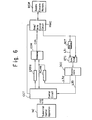
- Fig. 6 is a block diagram illustrating the principal portions of a bubble cassette memory control apparatus for advancing the head block of the file which is to be deleted, to the exists of the minor loops adjacent the read-only major line.
- a control circuit CCT controls the deletion of a file in response to a file deletion command FEC when the command is issued by a numerical control device NC.
- the command FEC indicates deletion of the n-th file F.
- the read/write control circuit RWC controls read and write operations in the bubble cassette memory BCM in response to signals from the control circuit CCT and from a comparator to be described below.
- a byte counter BCT having an l-byte capacity, has its content incremented by +1 each time one byte of data is read out of the bubble cassette memory BCM through the read/write control circuit RWC.
- the output of the byte counter BCT, delivered on line L 31' is logical "1" when the counter content is zero, and logical "0" at all other times, i.e., when the content is non-zero.
- the content of the counter BCT is restored to zero each time l, bytes of data enter from the read/write control circuit RWC. It will be recalled that the total number of bytes in one block is Q.
- a gate circuit GTC is open when the content of the byte counter BCT is zero, and closed when the counter content is non-zero. In other words, the gate circuit will pass only the control data in each block as it arrives from the read/write control circuit RWC.
- a discriminator DCC delivers logical "1" on line L 32 when a "1" is found to be stored in the eighth bit b 8 of a control byte, or line L 33 when a "1" is found to be stored in the first bit b 1 of the control byte.
- the discriminator DCC examines the control data arriving via the gate circuit GTC and delivers a "1" on line L 32 when the head block BH of a file is read out of the bubble memory, or on line L 33 when the data end block is read out of the bubble memory.
- a deletion file position register EFPR stores the position of the file to be deleted, where "position" means the ordinal number of the file from the head or first file. For example, when the numerical control device NC issues a file deletion command FEC calling for deletion of the i-th file, the numerical value i is stored in the deletion file position register EFPR.
- a current file position register FCPR is incremented by +1 each time a "1" arrives on line L 32 and thus stores the position of the file which is currently being read from the bubble memory.
- a comparator COM is adapted to deliver a coincidence signal CIN at logical "1" to the read/write control cicuit RWC when the deletion file position and the current file position coincide.
- the position n of the deletion file is set in the deletion file position register EFPR under the control circuit CCT when the numerical control device NC delivers the file deletion command FEC instructing deletion of the n-th file.
- the control circuit CCT concurrently sends a read command to the read/write control circuit RWC which responds by reading data from the head or beginning of the bubble cassette memory BCM, that is, by reading the data successively and non-destructively from the head file.
- This data enters the byte counter BCT whose content, it will be recalled, is zero as the initial bit of a block is read from the bubble memory, the counter delivering a "1" on line L 31 at such time.
- the discriminator GTC delivers a "1" on line L 32 each time it receives an item of control data having a "1" stored in the eighth bit b 8 1 each "1" pulse incrementing the current file position register FCPR by +1.
- a "1" appears on line L 32 whenever the control data in a head block is read, the current file position register FCPR having its content up counted by +1 as each "1" pulse arrives from the discriminator.
- the comparator COM constantly compares the deletion file position n and the current file position and delivers the coincidence signal CIN, namely logical "1", to the read/write control circuit RWC when the two comparator inputs coincide.
- the read/write control circuit RWC responds to the coincidence signal COI by halting the non-destructive read operation. When this occurs the head block of the deletion file (file F n ) is at the exits of the minor loops adjacent the read-only major line. Now a destructive read operation is performed to delete the file F and the files which follow F .
Landscapes
- Engineering & Computer Science (AREA)
- Computer Hardware Design (AREA)
- Information Retrieval, Db Structures And Fs Structures Therefor (AREA)
Applications Claiming Priority (2)
| Application Number | Priority Date | Filing Date | Title |
|---|---|---|---|
| JP133306/80 | 1980-09-25 | ||
| JP55133306A JPS5758292A (en) | 1980-09-25 | 1980-09-25 | File deleting method for bubble cassette memory |
Publications (3)
| Publication Number | Publication Date |
|---|---|
| EP0049113A2 true EP0049113A2 (de) | 1982-04-07 |
| EP0049113A3 EP0049113A3 (en) | 1984-01-04 |
| EP0049113B1 EP0049113B1 (de) | 1987-12-16 |
Family
ID=15101577
Family Applications (1)
| Application Number | Title | Priority Date | Filing Date |
|---|---|---|---|
| EP81304401A Expired EP0049113B1 (de) | 1980-09-25 | 1981-09-24 | Dateilöschung in einem Blasenkassettenspeicher und Steueranordnung für einen Blasenkassettenspeicher |
Country Status (5)
| Country | Link |
|---|---|
| US (1) | US4481606A (de) |
| EP (1) | EP0049113B1 (de) |
| JP (1) | JPS5758292A (de) |
| KR (1) | KR880002574B1 (de) |
| DE (1) | DE3176579D1 (de) |
Cited By (3)
| Publication number | Priority date | Publication date | Assignee | Title |
|---|---|---|---|---|
| EP0130218A4 (de) * | 1982-12-29 | 1987-02-26 | Fanuc Ltd | Verfahren zum abschirmen des numerischen datenbestandes. |
| EP0181407A4 (de) * | 1984-05-09 | 1987-11-23 | Fanuc Ltd | Karteisteuerungsverfahren. |
| EP1042125B1 (de) * | 1998-10-23 | 2004-05-26 | François Trantoul | Verfahren zum herstellen eines mehrfarbigen fotolumineszierenden bildes, so hergestelltes bild und seine anwendungen |
Families Citing this family (6)
| Publication number | Priority date | Publication date | Assignee | Title |
|---|---|---|---|---|
| US4835739A (en) * | 1987-08-04 | 1989-05-30 | Grumman Aerospace Corporation | Mass storage bubble memory system |
| JPH04236664A (ja) * | 1991-01-18 | 1992-08-25 | Sony Corp | 演算回路 |
| US6247024B1 (en) | 1998-09-25 | 2001-06-12 | International Business Machines Corporation | Method and system for performing deferred file removal in a file system |
| CN101390050B (zh) | 2005-12-22 | 2018-04-24 | 艾伦·J·薛比洛 | 通过相减性安装达成选择性分配软件资源的装置与方法 |
| US20070150887A1 (en) * | 2005-12-22 | 2007-06-28 | Shapiro Alan J | Apparatus and method for selectively dispensing soft assets |
| US9286308B2 (en) | 2005-12-22 | 2016-03-15 | Alan Joshua Shapiro | System and method for metadata modification |
Family Cites Families (12)
| Publication number | Priority date | Publication date | Assignee | Title |
|---|---|---|---|---|
| US3427596A (en) * | 1967-03-07 | 1969-02-11 | North American Rockwell | System for processing data into an organized sequence of computer words |
| US3737881A (en) * | 1972-04-13 | 1973-06-05 | Ibm | Implementation of the least recently used (lru) algorithm using magnetic bubble domains |
| US3967263A (en) * | 1974-05-14 | 1976-06-29 | International Business Machines Corporation | Text editing system |
| JPS512302A (en) * | 1974-06-24 | 1976-01-09 | Fujitsu Ltd | Johotensohoshiki |
| US4037205A (en) * | 1975-05-19 | 1977-07-19 | Sperry Rand Corporation | Digital memory with data manipulation capabilities |
| US4021791A (en) * | 1976-04-20 | 1977-05-03 | Bell Telephone Laboratories, Incorporated | Magnetic bubble PROM memory |
| US4161788A (en) * | 1977-04-21 | 1979-07-17 | Texas Instruments Incorporated | Bubble memory controller with multipage data handling |
| US4130894A (en) * | 1977-11-21 | 1978-12-19 | International Business Machines Corporation | Loop organized serial-parallel-serial memory storage system |
| US4221003A (en) * | 1978-05-04 | 1980-09-02 | International Business Machines Corporation | Bubble domain relational data base system |
| US4283771A (en) * | 1978-07-31 | 1981-08-11 | International Business Machines Corporation | On-chip bubble domain relational data base system |
| US4225941A (en) * | 1978-10-30 | 1980-09-30 | Trw Inc. | Controller for bubble memories |
| US4308593A (en) * | 1979-05-14 | 1981-12-29 | Microcomputer Systems Corporation | Interchangeable magnetic bubble memory |
-
1980
- 1980-09-25 JP JP55133306A patent/JPS5758292A/ja active Pending
-
1981
- 1981-09-08 US US06/300,213 patent/US4481606A/en not_active Expired - Fee Related
- 1981-09-19 KR KR1019810003504A patent/KR880002574B1/ko not_active Expired
- 1981-09-24 EP EP81304401A patent/EP0049113B1/de not_active Expired
- 1981-09-24 DE DE8181304401T patent/DE3176579D1/de not_active Expired
Cited By (4)
| Publication number | Priority date | Publication date | Assignee | Title |
|---|---|---|---|---|
| EP0130218A4 (de) * | 1982-12-29 | 1987-02-26 | Fanuc Ltd | Verfahren zum abschirmen des numerischen datenbestandes. |
| US4884211A (en) * | 1982-12-29 | 1989-11-28 | Fanuc Ltd. | Numerical control unit file protection system |
| EP0181407A4 (de) * | 1984-05-09 | 1987-11-23 | Fanuc Ltd | Karteisteuerungsverfahren. |
| EP1042125B1 (de) * | 1998-10-23 | 2004-05-26 | François Trantoul | Verfahren zum herstellen eines mehrfarbigen fotolumineszierenden bildes, so hergestelltes bild und seine anwendungen |
Also Published As
| Publication number | Publication date |
|---|---|
| KR830008323A (ko) | 1983-11-18 |
| KR880002574B1 (ko) | 1988-11-30 |
| JPS5758292A (en) | 1982-04-07 |
| EP0049113A3 (en) | 1984-01-04 |
| US4481606A (en) | 1984-11-06 |
| DE3176579D1 (en) | 1988-01-28 |
| EP0049113B1 (de) | 1987-12-16 |
Similar Documents
| Publication | Publication Date | Title |
|---|---|---|
| US3312948A (en) | Record format control circuit | |
| US4210959A (en) | Controller for magnetic disc, recorder, or the like | |
| US5335235A (en) | FIFO based parity generator | |
| US4481606A (en) | File deletion method in bubble cassette memory, and bubble cassette memory control apparatus | |
| US3107343A (en) | Information retrieval system | |
| US2969525A (en) | Locating information | |
| US3348213A (en) | Record retrieval control unit | |
| US4354253A (en) | Bubble redundancy map storage using non-volatile semiconductor memory | |
| US3327294A (en) | Flag storage system | |
| US3311891A (en) | Recirculating memory device with gated inputs | |
| US3594734A (en) | Programmable calculator | |
| GB1118887A (en) | Digital data storage system | |
| US3587062A (en) | Read-write control system for a recirculating storage means | |
| USRE25405E (en) | T register | |
| US3533071A (en) | Data transfer system and method | |
| US4078258A (en) | System for arranging and sharing shift register memory | |
| US3411145A (en) | Multiplexing and demultiplexing of related time series data records | |
| US3427596A (en) | System for processing data into an organized sequence of computer words | |
| JPS5841578B2 (ja) | 回転形記憶装置の制御方法 | |
| US3286235A (en) | Information storage system | |
| US4084258A (en) | Apparatus for performing multiple operations in a shift register memory | |
| US3999172A (en) | Magnetic domain memory | |
| US2984827A (en) | Phase alternating status keeper | |
| JPS5913109B2 (ja) | デ−タ記憶方式 | |
| US3350693A (en) | Multiple section transfer system |
Legal Events
| Date | Code | Title | Description |
|---|---|---|---|
| PUAI | Public reference made under article 153(3) epc to a published international application that has entered the european phase |
Free format text: ORIGINAL CODE: 0009012 |
|
| AK | Designated contracting states |
Designated state(s): CH DE FR GB |
|
| RBV | Designated contracting states (corrected) |
Designated state(s): BE CH DE FR GB LI LU NL SE |
|
| RBV | Designated contracting states (corrected) |
Designated state(s): CH CH DE FR GB |
|
| RAP1 | Party data changed (applicant data changed or rights of an application transferred) |
Owner name: FANUC LIMITED |
|
| PUAL | Search report despatched |
Free format text: ORIGINAL CODE: 0009013 |
|
| AK | Designated contracting states |
Designated state(s): CH DE FR GB |
|
| 17P | Request for examination filed |
Effective date: 19840625 |
|
| RAP1 | Party data changed (applicant data changed or rights of an application transferred) |
Owner name: FANUC LTD |
|
| GRAA | (expected) grant |
Free format text: ORIGINAL CODE: 0009210 |
|
| AK | Designated contracting states |
Kind code of ref document: B1 Designated state(s): CH DE FR GB LI |
|
| REF | Corresponds to: |
Ref document number: 3176579 Country of ref document: DE Date of ref document: 19880128 |
|
| ET | Fr: translation filed | ||
| PLBE | No opposition filed within time limit |
Free format text: ORIGINAL CODE: 0009261 |
|
| STAA | Information on the status of an ep patent application or granted ep patent |
Free format text: STATUS: NO OPPOSITION FILED WITHIN TIME LIMIT |
|
| 26N | No opposition filed | ||
| PGFP | Annual fee paid to national office [announced via postgrant information from national office to epo] |
Ref country code: GB Payment date: 19910806 Year of fee payment: 11 |
|
| PGFP | Annual fee paid to national office [announced via postgrant information from national office to epo] |
Ref country code: FR Payment date: 19910904 Year of fee payment: 11 |
|
| PG25 | Lapsed in a contracting state [announced via postgrant information from national office to epo] |
Ref country code: GB Effective date: 19920924 |
|
| GBPC | Gb: european patent ceased through non-payment of renewal fee |
Effective date: 19920924 |
|
| PG25 | Lapsed in a contracting state [announced via postgrant information from national office to epo] |
Ref country code: FR Effective date: 19930528 |
|
| REG | Reference to a national code |
Ref country code: FR Ref legal event code: ST |
|
| PGFP | Annual fee paid to national office [announced via postgrant information from national office to epo] |
Ref country code: DE Payment date: 19930922 Year of fee payment: 13 |
|
| PGFP | Annual fee paid to national office [announced via postgrant information from national office to epo] |
Ref country code: CH Payment date: 19930929 Year of fee payment: 13 |
|
| PG25 | Lapsed in a contracting state [announced via postgrant information from national office to epo] |
Ref country code: LI Effective date: 19940930 Ref country code: CH Effective date: 19940930 |
|
| REG | Reference to a national code |
Ref country code: CH Ref legal event code: PL |
|
| PG25 | Lapsed in a contracting state [announced via postgrant information from national office to epo] |
Ref country code: DE Effective date: 19950601 |