EP0049116A2 - Speisewasservorwärmer - Google Patents
Speisewasservorwärmer Download PDFInfo
- Publication number
- EP0049116A2 EP0049116A2 EP81304410A EP81304410A EP0049116A2 EP 0049116 A2 EP0049116 A2 EP 0049116A2 EP 81304410 A EP81304410 A EP 81304410A EP 81304410 A EP81304410 A EP 81304410A EP 0049116 A2 EP0049116 A2 EP 0049116A2
- Authority
- EP
- European Patent Office
- Prior art keywords
- tube
- feedwater
- nest
- shell
- tube nest
- Prior art date
- Legal status (The legal status is an assumption and is not a legal conclusion. Google has not performed a legal analysis and makes no representation as to the accuracy of the status listed.)
- Granted
Links
Images
Classifications
-
- F—MECHANICAL ENGINEERING; LIGHTING; HEATING; WEAPONS; BLASTING
- F28—HEAT EXCHANGE IN GENERAL
- F28D—HEAT-EXCHANGE APPARATUS, NOT PROVIDED FOR IN ANOTHER SUBCLASS, IN WHICH THE HEAT-EXCHANGE MEDIA DO NOT COME INTO DIRECT CONTACT
- F28D7/00—Heat-exchange apparatus having stationary tubular conduit assemblies for both heat-exchange media, the media being in contact with different sides of a conduit wall
- F28D7/06—Heat-exchange apparatus having stationary tubular conduit assemblies for both heat-exchange media, the media being in contact with different sides of a conduit wall the conduits having a single U-bend
-
- F—MECHANICAL ENGINEERING; LIGHTING; HEATING; WEAPONS; BLASTING
- F22—STEAM GENERATION
- F22D—PREHEATING, OR ACCUMULATING PREHEATED, FEED-WATER FOR STEAM GENERATION; FEED-WATER SUPPLY FOR STEAM GENERATION; CONTROLLING WATER LEVEL FOR STEAM GENERATION; AUXILIARY DEVICES FOR PROMOTING WATER CIRCULATION WITHIN STEAM BOILERS
- F22D1/00—Feed-water heaters, i.e. economisers or like preheaters
- F22D1/32—Feed-water heaters, i.e. economisers or like preheaters arranged to be heated by steam, e.g. bled from turbines
-
- F—MECHANICAL ENGINEERING; LIGHTING; HEATING; WEAPONS; BLASTING
- F28—HEAT EXCHANGE IN GENERAL
- F28B—STEAM OR VAPOUR CONDENSERS
- F28B9/00—Auxiliary systems, arrangements, or devices
- F28B9/10—Auxiliary systems, arrangements, or devices for extracting, cooling, and removing non-condensable gases
-
- F—MECHANICAL ENGINEERING; LIGHTING; HEATING; WEAPONS; BLASTING
- F28—HEAT EXCHANGE IN GENERAL
- F28F—DETAILS OF HEAT-EXCHANGE AND HEAT-TRANSFER APPARATUS, OF GENERAL APPLICATION
- F28F9/00—Casings; Header boxes; Auxiliary supports for elements; Auxiliary members within casings
- F28F9/02—Header boxes; End plates
- F28F9/0202—Header boxes having their inner space divided by partitions
-
- Y—GENERAL TAGGING OF NEW TECHNOLOGICAL DEVELOPMENTS; GENERAL TAGGING OF CROSS-SECTIONAL TECHNOLOGIES SPANNING OVER SEVERAL SECTIONS OF THE IPC; TECHNICAL SUBJECTS COVERED BY FORMER USPC CROSS-REFERENCE ART COLLECTIONS [XRACs] AND DIGESTS
- Y10—TECHNICAL SUBJECTS COVERED BY FORMER USPC
- Y10S—TECHNICAL SUBJECTS COVERED BY FORMER USPC CROSS-REFERENCE ART COLLECTIONS [XRACs] AND DIGESTS
- Y10S165/00—Heat exchange
- Y10S165/184—Indirect-contact condenser
- Y10S165/205—Space for condensable vapor surrounds space for coolant
- Y10S165/207—Distinct outlets for separated condensate and gas
- Y10S165/211—Distinct outlets for separated condensate and gas including concave member adjacent to vapor outlet and partially covering a group of coolant tubes
Definitions
- the present invention relates to a feedwater heater for use in heat power stations or nuclear power stations and, more particularly, to a feedwater heater of the type having a multiplicity of U-shaped heat transfer tubes and a vent tube for discharging the non-condensed gas in the heater.
- the feedwater heater of a horizontal type has a barrel or a shell the inside of which is divided into sections by a tube plate which is normal to the axis of the shell. More specifically, at one end of the shell, defined is a water chamber section consisting of a water inlet chamber having a water inlet opening and a water outlet chamber having a water outlet opening. A plurality of heat transfer tubes are bent at their mid portions and are extended along the axis of the shell.
- the heat transfer tubes are supported by a plurality of tube supporting plates spaced at a suitable pitch in the longitudinal direction of the tubes.
- An inlet opening for steam and drain is formed in the top of the shell.
- a vent tube for discharging the non-condensed gas is disposed between the tube nest of the water inlet side, i.e. the lower tube nest, and the tube nest of the water outlet side, i.e. the upper tube nest, to permit the discharge of the non-condensed gas.
- the feedwater coming into the feedwater heater from the water inlet chamber flows through the U-shaped heat transfer tubes and absorbs the heat from the heating steam coming into the feedwater heater from the steam inlet opening to condense the steam.
- the condensate is collected at the bottom of the shell and is discharged to the outside through a drain cooler which is located near the tube plate and surrounding the tube nest of the feedwater inlet side.
- the feedwater heater of this kind having more than one turn of the flow of feedwater, there is a large temperature difference of the feedwater between the tube nest of the feedwater inlet side and the tube nest of the feedwater outlet side.
- the ratio of amount of heat exchanged in the inlet side tube nest to the amount of heat exchanged in the outlet side tube nest is as large as 20 : 1, so that a region of stagnation of steam is formed in the feedwater inlet side tube nest of the greater heat exchange.
- the non-condensed gas is inconveniently accumulated in this region. In consequence, the non-condensed gas is not concentrated to the vent tube and, hence, cannot be discharged smoothly, resulting in a corrosion of the heat transfer tubes in this region, as well as deteriorated transfer of the heat.
- an object of the invention is to provide a feedwater heater which is free from the problem of corrosion of the shell, tube plate and tubes due to the stagnation of the non-condensed gas, while maintaining a high heat exchanging performance.
- Another object of the invention is to provide a feedwater heater constructed with a material having a high resistance against corrosion even in the atmosphere where the saturated steam of high temperature and non-condensed gas exist together.
- a feedwater heater having a plurality of U-shaped heat transfer tubes arranged to form a lower tube nest disposed at the feedwater inlet side and an upper tube nest disposed at the feedwater outlet side, and a vent tube disposed between the upper and the lower tube nest and adapted for discharging non-condensed gas
- the feedwater heater comprising baffles attached to the vent tube and adapted to interrupt the flow of steam coming down from the upper tube nest into the lower tube nest, the projection lengths of the baffles being varied along the length of the feedwater heater in accordance with the change of ratio of amount of heat exchanged between the feedwater and the steam in the lower tube nest to the amount of heat exchanged between the feedwater and the steam in the upper tube nest.
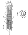
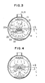
- a feedwater heater of the invention has a horizontally mounted shell 1 the inside of which is divided by a tube plate 2 into a water chamber section 5 defined at one end of the shell 1 and a steam chamber section.
- the water chamber section 5 is further sectioned into an inlet chamber 5a having a feedwater inlet 3 and a water outlet chamber 5b having a feedwater outlet 4.
- a plurality of heat transfer tubes 6 are arrayed in the form of a tube nest along the length of the shell 1.
- Each heat transfer tube is bent in a U-like shape at its mid portion.
- the heat transfer tubes 6 are fixed at their both ends to the tube plate 2 such that their one ends open to the water inlet chamber 5a while the other ends open to the water outlet chambers 5b.
- the heat transfer tubes 6 are supported by a plurality of tube supporting plates 7 which are perpendicular to the axis of the shell 1 and spaced in the longitudinal direction of the same.
- the tube supporting plates 7 are secured to the tube plate 2 by means of tie rods 8.
- a steam inlet opening 9 and a drain inlet opening 10 are formed in the top surface of the shell 1.
- a drain coller 11 for cooling the condensate or drain in the shell 1 is disposed in the vicinity of the tube plate 2 in such a manner as to surround the tube nest of the feedwater inlet side.
- the drain accumulated on the bottom of the barrel is sucked up into the cooler 11 through an inlet formed in the lower face of the cooler 11 to fill the cavity in the latter, and is discharged from the drain discharge port 12 by means of a drain pump.
- a vent tube 15 for discharging the non-condensed gas is attached to a portion between the tube nest 14 of the feedwater inlet side (lower tube nest) and the tube nest 13 of the feedwater outlet side (upper tube nest), to permit the discharge of the non-condensed gas to the outside of the shell.
- the vent tube 15 is provided with orifice holes 17 located in each section 16 of the tube nest defined by the tube supporting plates. The diameters of these orifice holes are determined to correspond to the amounts of heat exchanged in respective sections 16.
- the non-condensed gas attracted through these orifice holes 17 is made to flow across the tube nest through a guide tube 18 connected to the end of the vent tube 15, and is discharged through a vent seat 19 to a deaerator or a condenser maintained at a pressure sufficiently lower than the pressure in the feedwater heater.
- Gas collecting baffles 20 are secured to both sides of the vent tube 15 to extend along the length of the latter.
- the tube nest has vacant spaces 21 to permit the baffles 20 to pass therethrough.
- Each tube supporting plate 7 is provided with an upper notch 49 to permit the steam coming into each tube nest section 16 through the steam inlet opening 9 to freely flow as indicated by an arrow 22, so as to form a passage 23 for the steam.
- the steam, steam-drain mixture and the drain coming through the steam and drain inlet openings 9, 10 are made to expand in the space of the passage 23 so that the steam flows over all tube nest sections 16 of the whole length of the feedwater heater.
- the sectional area of the flow passage for the steam is sufficiently increased to sufficiently lower the flowing velocity of the steam.
- tube supporting plates notched at the upper side and the tube supporting plates notched at the lower side are arranged alternatingly, so that the steam passage is wound up and down to have a small sectional area to cause a considerably high flowing velocity of the steam, with a consequence to promote the corrosion and erosion of the tubes. According to the invention, however, this problem is eliminated because the flowing velocity of the steam can be lowered sufficiently.
- each tube supporting plate 7 is notched also at its lateral sides as at 50 so that the steam passages are formed also at both side portions of the shell 1. It is, therefore, possible to release the steam accumulated in one tube nest section 16 to another tube nest section 16 of a lower pressure to achieve a flow pattern corresponding to the heat exchanging capacities of respective tube nest sections 16.
- the shell 1 and the internal structure is nade of a steel containing more than 1% of Cr to exhibit a sufficient corrosion and erosion resistances.
- the shell and the internal structure are made of a carbon steel so that, when the steam-water mixture coming through the drain inlet opening 10 and the steam coming through the steam inlet opening 9 have low pH values, the corrosion and erosion proceed rapidly. Particularly, the reduction of wall thickness of the shell is serious.
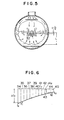
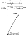
- gas collecting baffles 20 are secured to both sides of the vent tube 15 in such a manner as to interrupt the flow of steam from the tube nest 13 of the feedwater outlet side. It is, therefore, possible to form a low pressure region 33 adjacent to the region 32 of stagnation of the non-condensed gas and, accordingly, the non-condensed gas can be efficiently sucked through the vent tube 15. More specifically, the steam coming into the shell 1 through the steam inlet opening 9 flows as indicated by the arrow 22 in Fig. 1, and then flows downwardly from the upper tube nest 13 to the lower tube nest-14 as indicated by an arrow 31 in Fig. 3. In the conventional feedwater heater, it is not possible to efficiently concentrate the non-condensed gas to the area around the vent tube 15 with a consequence to lower the efficiency of extraction of the non-condensed gas.
- gas collecting baffles 20 are attached to both sides of the vent tube 15.
- Each baffle has a horizontal plate portion 20a projected laterally from one side of the vent tube 15 into the descending flow of the steam and an inclined plate portion 20b extended obliquely downwardly from the end of the horizontal plate portion 20a toward the tube nest 14 of the feedwater inlet side, i.e. the lower tube nest, at an obtuse angle to the horizontal plate portion 20a.
- two baffles 20 are arranged in a manner to diverge toward the lower side.
- the steam coming down from the upper tube nest collides with the baffles 20 and is made to flow downwardly in a diverging manner into the lower tube nest 14 along the inclined plate portions 20b of the baffles 20.
- the steam is then condensed and accumulated on the bottom of the shell, while the non-condensed gas is induced to the low pressure region 33 defined by the inclined plate portions 20b of two baffles 20 and is then sucked into the vent tube 15.
- Fig. 6 shows the temperature characteristics in the feedwater heater. Symbols used in Fig. 6 represent the following factors, respectively.
- Reference numerals 34 to 45 denote tube nest sections in accordance with the flow of the feedwater. Namely, the reference numeral 34 denotes the first tube nest section, i.e. the feedwater inlet side section (lower tube nest section), while the reference numeral 45 denotes the last tube nest section (upper tube nest section).
- the steam temperature T of the steam side is the saturation temperature corresponding to the steam pressure in the steam side of the feedwater heater.
- the feedwater flows into the inlet side section 34 at the inlet temperature t l and is heated up to t l ' as it reaches the upsteam end of the lower tube nest section 35.
- the feedwater is then progressively heated as it flows through successive tube nest sections, and reaches the temperature t 2 1 when it leaves the upper tube nest section 44 and is finally discharged from the feedwater heater at the final outlet temperature t 2 .
- At represents the temperature difference between the steam side and the feedwater side in each tube nets section.
- ratio of amount of heat exchanged in a tube nest section of the lower tube nest to that exchanged in the corresponding tube nest section in the upper tube nest is referred to as "ratio of amount of heat exchanged", in this specification.
- ratio of amount of heat exchanged is greatest in the sections closest to the tube plate 2.
- This ratio generally takes a value of about 1 : 5 in the case of nuclear power plants and about 1 : 20 in the case of ordinary heat power stations.
- the ratio of amount of heat exchanged is gradually lowered toward the bend end of the tube nest, and takes a value of about 1 : 1 in the sections closest to the bent end of the tubes.
- This variation of the value of the ratio of the amount of heat exchanged creates various conditions concerning the flow rates and velocities of the steam coming down from the upper tube nest and the steam upwardly induced into the low-pressure region formed by the baffles.
- the upward flow of steam becomes dominant to spread the region 32 of stagnation of the non-condensed gas to the area surrounding the baffles 20, if the size & of the baffle 20 is selected to be large.
- Figs. 7(a) and 7(b) show the preferred relationship between the axial position of the tube nest sections and the length l of the baffles for collecting the non-condensed gas.
- the baffle length takes the maximum value in the tube nest section 16a closest to the tube closest to the tube plate. This maximum length preferably amounts to 1/3 (one third) of the depth L of the tube nest.
- the preferred baffle length t is gradually decreased toward the tube nest section 16b closest to the U bend of the tubes.
- the length l of the baffles is preferably determined following the curve 48 in Fig. 7(b) along the longitudinal axis of the feedwater heater.
Landscapes
- Engineering & Computer Science (AREA)
- Mechanical Engineering (AREA)
- General Engineering & Computer Science (AREA)
- Physics & Mathematics (AREA)
- Thermal Sciences (AREA)
- Heat-Exchange Devices With Radiators And Conduit Assemblies (AREA)
- Details Of Heat-Exchange And Heat-Transfer (AREA)
Applications Claiming Priority (2)
| Application Number | Priority Date | Filing Date | Title |
|---|---|---|---|
| JP55134330A JPS5914682B2 (ja) | 1980-09-29 | 1980-09-29 | 給水加熱器 |
| JP134330/80 | 1980-09-29 |
Publications (3)
| Publication Number | Publication Date |
|---|---|
| EP0049116A2 true EP0049116A2 (de) | 1982-04-07 |
| EP0049116A3 EP0049116A3 (en) | 1982-06-23 |
| EP0049116B1 EP0049116B1 (de) | 1984-06-27 |
Family
ID=15125804
Family Applications (1)
| Application Number | Title | Priority Date | Filing Date |
|---|---|---|---|
| EP81304410A Expired EP0049116B1 (de) | 1980-09-29 | 1981-09-24 | Speisewasservorwärmer |
Country Status (4)
| Country | Link |
|---|---|
| US (1) | US4461346A (de) |
| EP (1) | EP0049116B1 (de) |
| JP (1) | JPS5914682B2 (de) |
| DE (1) | DE3164443D1 (de) |
Cited By (2)
| Publication number | Priority date | Publication date | Assignee | Title |
|---|---|---|---|---|
| EP0325758A1 (de) * | 1988-01-22 | 1989-08-02 | Asea Brown Boveri Ag | Dampfkondensator |
| EP1386057A4 (de) * | 2001-05-07 | 2009-12-16 | Joseph W C Harpster | Kondensatoren und ihre überwachung |
Families Citing this family (13)
| Publication number | Priority date | Publication date | Assignee | Title |
|---|---|---|---|---|
| DE3461332D1 (en) * | 1983-04-29 | 1987-01-02 | Bbc Brown Boveri & Cie | Feed-water heater |
| US4858564A (en) * | 1988-05-16 | 1989-08-22 | Foster Wheeler Energy Corporation | Feedwater heater with improved steam distribution |
| US5200039A (en) * | 1991-01-18 | 1993-04-06 | Emerson Electric Co. | Steam chamber for a water distiller with contamination prevention baffle and check valve |
| DE4311118A1 (de) * | 1993-04-05 | 1994-10-06 | Abb Management Ag | Dampfkondensator |
| JP4230841B2 (ja) * | 2003-07-30 | 2009-02-25 | 株式会社東芝 | 復水器 |
| EP1508763B1 (de) * | 2003-08-21 | 2007-11-07 | Balcke-Dürr GmbH | Verfahren zur Anordnung eines Entlüftungsrohres in einem Wärmetauscher |
| JP4913206B2 (ja) * | 2006-03-27 | 2012-04-11 | バラット ヘビー エレクトリカルズ リミテッド | 2管路式管巣体構造の復水器 |
| US9285172B2 (en) * | 2009-04-29 | 2016-03-15 | Westinghouse Electric Company Llc | Modular plate and shell heat exchanger |
| US20120103578A1 (en) | 2009-04-29 | 2012-05-03 | Westinghouse Electric Company Llc | Modular plate and shell heat exchanger |
| JP6087597B2 (ja) * | 2012-11-28 | 2017-03-01 | 三菱重工業株式会社 | 熱交換器 |
| CN104101249A (zh) * | 2014-07-23 | 2014-10-15 | 安庆市东徽机械有限公司 | 换热器防冲机构 |
| CN105114938A (zh) * | 2015-09-18 | 2015-12-02 | 上海电气电站设备有限公司 | 一种蛇形管式高压给水加热器 |
| CN110005484B (zh) * | 2019-03-07 | 2021-10-15 | 大唐东营发电有限公司 | 一种卧式汽轮机低压加热器 |
Family Cites Families (12)
| Publication number | Priority date | Publication date | Assignee | Title |
|---|---|---|---|---|
| US1764716A (en) * | 1926-02-11 | 1930-06-17 | Elliott Co | Condenser |
| US2021009A (en) * | 1934-05-16 | 1935-11-12 | Thomas H Ireland | Heat exchanger |
| US2180840A (en) * | 1937-11-27 | 1939-11-21 | Westinghouse Electric & Mfg Co | Condenser apparatus |
| US3706301A (en) * | 1971-07-13 | 1972-12-19 | Combustion Eng | Integral economizer for u-tube generator |
| US3795273A (en) * | 1972-06-12 | 1974-03-05 | Foster Wheeler Corp | Feedwater heater |
| US3938588A (en) * | 1973-10-18 | 1976-02-17 | Westinghouse Electric Corporation | Deaerating feedwater heater |
| JPS526804A (en) * | 1975-07-05 | 1977-01-19 | Hitachi Ltd | H-shell water heater |
| JPS53147103A (en) * | 1977-05-27 | 1978-12-21 | Hitachi Ltd | Multitubular system heat exchager |
| JPS5468555A (en) * | 1977-11-11 | 1979-06-01 | Hitachi Ltd | Multi tube type heat exchanger |
| DE2820736A1 (de) * | 1978-05-12 | 1979-11-15 | Bbc Brown Boveri & Cie | Speisewasservorwaermer |
| CH628410A5 (de) * | 1978-05-31 | 1982-02-26 | Bbc Brown Boveri & Cie | Speisewasservorwaermer. |
| JPS5844198B2 (ja) * | 1978-10-05 | 1983-10-01 | 株式会社日立製作所 | 多管式熱交換器 |
-
1980
- 1980-09-29 JP JP55134330A patent/JPS5914682B2/ja not_active Expired
-
1981
- 1981-09-24 DE DE8181304410T patent/DE3164443D1/de not_active Expired
- 1981-09-24 EP EP81304410A patent/EP0049116B1/de not_active Expired
- 1981-09-28 US US06/306,234 patent/US4461346A/en not_active Expired - Lifetime
Cited By (3)
| Publication number | Priority date | Publication date | Assignee | Title |
|---|---|---|---|---|
| EP0325758A1 (de) * | 1988-01-22 | 1989-08-02 | Asea Brown Boveri Ag | Dampfkondensator |
| US4967833A (en) * | 1988-01-22 | 1990-11-06 | Asea Brown Boveri Ltd. | Steam condenser |
| EP1386057A4 (de) * | 2001-05-07 | 2009-12-16 | Joseph W C Harpster | Kondensatoren und ihre überwachung |
Also Published As
| Publication number | Publication date |
|---|---|
| JPS5760102A (en) | 1982-04-10 |
| EP0049116A3 (en) | 1982-06-23 |
| US4461346A (en) | 1984-07-24 |
| DE3164443D1 (en) | 1984-08-02 |
| JPS5914682B2 (ja) | 1984-04-05 |
| EP0049116B1 (de) | 1984-06-27 |
Similar Documents
| Publication | Publication Date | Title |
|---|---|---|
| US4461346A (en) | Feedwater heater | |
| CA1097159A (en) | Tube bundle | |
| CA1097334A (en) | Multitubular heat exchanger used in a power plant | |
| US2134058A (en) | Heat exchanger | |
| US4252186A (en) | Condenser with improved heat transfer | |
| KR100194778B1 (ko) | 복수기 | |
| US4254825A (en) | Multitubular heat exchanger | |
| US4226283A (en) | Multitubular heat exchanger | |
| JP4230841B2 (ja) | 復水器 | |
| DE112007003550T5 (de) | Kessel mit flachen horizontalen Röhren | |
| US2812164A (en) | Heat exchanger | |
| US4240502A (en) | Condensing heat exchanger | |
| CN108709437A (zh) | 污氮加热器管箱结构及使用方法 | |
| CN217504441U (zh) | 一种蒸汽加热装置 | |
| JP3483697B2 (ja) | 沸騰水型原子炉の給水加熱器 | |
| JPS6137994Y2 (de) | ||
| RU2037121C1 (ru) | Теплообменник | |
| JP2677661B2 (ja) | 湿分分離加熱器 | |
| JP2511149B2 (ja) | 給水加熱器 | |
| EP0110545A1 (de) | Wärmeübertragungsverfahren | |
| JP2573806Y2 (ja) | シェル・アンド・チューブ式吸収凝縮器 | |
| Butterworth | Condensers and their design | |
| JP2001153301A (ja) | 排ガス用熱交換器 | |
| JPS5947836B2 (ja) | 蒸気復水器 | |
| JPS5913808A (ja) | 給水加熱器 |
Legal Events
| Date | Code | Title | Description |
|---|---|---|---|
| PUAI | Public reference made under article 153(3) epc to a published international application that has entered the european phase |
Free format text: ORIGINAL CODE: 0009012 |
|
| AK | Designated contracting states |
Designated state(s): DE FR GB SE |
|
| PUAL | Search report despatched |
Free format text: ORIGINAL CODE: 0009013 |
|
| 17P | Request for examination filed |
Effective date: 19820311 |
|
| AK | Designated contracting states |
Designated state(s): DE FR GB SE |
|
| RBV | Designated contracting states (corrected) |
Designated state(s): BE CH DE FR GB IT LI LU NL SE |
|
| RBV | Designated contracting states (corrected) |
Designated state(s): DE FR GB SE |
|
| GRAA | (expected) grant |
Free format text: ORIGINAL CODE: 0009210 |
|
| AK | Designated contracting states |
Designated state(s): DE FR GB SE |
|
| REF | Corresponds to: |
Ref document number: 3164443 Country of ref document: DE Date of ref document: 19840802 |
|
| ET | Fr: translation filed | ||
| PLBE | No opposition filed within time limit |
Free format text: ORIGINAL CODE: 0009261 |
|
| STAA | Information on the status of an ep patent application or granted ep patent |
Free format text: STATUS: NO OPPOSITION FILED WITHIN TIME LIMIT |
|
| 26N | No opposition filed | ||
| EAL | Se: european patent in force in sweden |
Ref document number: 81304410.4 |
|
| PGFP | Annual fee paid to national office [announced via postgrant information from national office to epo] |
Ref country code: SE Payment date: 19970623 Year of fee payment: 17 |
|
| PGFP | Annual fee paid to national office [announced via postgrant information from national office to epo] |
Ref country code: GB Payment date: 19970624 Year of fee payment: 17 |
|
| PG25 | Lapsed in a contracting state [announced via postgrant information from national office to epo] |
Ref country code: GB Free format text: LAPSE BECAUSE OF NON-PAYMENT OF DUE FEES Effective date: 19980924 |
|
| PG25 | Lapsed in a contracting state [announced via postgrant information from national office to epo] |
Ref country code: SE Free format text: LAPSE BECAUSE OF NON-PAYMENT OF DUE FEES Effective date: 19980925 |
|
| GBPC | Gb: european patent ceased through non-payment of renewal fee |
Effective date: 19980924 |
|
| EUG | Se: european patent has lapsed |
Ref document number: 81304410.4 |
|
| PGFP | Annual fee paid to national office [announced via postgrant information from national office to epo] |
Ref country code: FR Payment date: 20000823 Year of fee payment: 20 |
|
| PGFP | Annual fee paid to national office [announced via postgrant information from national office to epo] |
Ref country code: DE Payment date: 20000929 Year of fee payment: 20 |