EP0049170A2 - Séchoir à tambour rotatif - Google Patents
Séchoir à tambour rotatif Download PDFInfo
- Publication number
- EP0049170A2 EP0049170A2 EP81304529A EP81304529A EP0049170A2 EP 0049170 A2 EP0049170 A2 EP 0049170A2 EP 81304529 A EP81304529 A EP 81304529A EP 81304529 A EP81304529 A EP 81304529A EP 0049170 A2 EP0049170 A2 EP 0049170A2
- Authority
- EP
- European Patent Office
- Prior art keywords
- machine
- heat source
- drum
- air
- temperature
- Prior art date
- Legal status (The legal status is an assumption and is not a legal conclusion. Google has not performed a legal analysis and makes no representation as to the accuracy of the status listed.)
- Withdrawn
Links
- 238000001035 drying Methods 0.000 title abstract description 26
- 238000010438 heat treatment Methods 0.000 claims description 8
- 238000000034 method Methods 0.000 claims description 5
- 239000003570 air Substances 0.000 description 44
- 239000004677 Nylon Substances 0.000 description 2
- 239000012080 ambient air Substances 0.000 description 2
- 230000001419 dependent effect Effects 0.000 description 2
- 239000000463 material Substances 0.000 description 2
- 230000007935 neutral effect Effects 0.000 description 2
- 229920001778 nylon Polymers 0.000 description 2
- 239000002699 waste material Substances 0.000 description 2
- 230000015572 biosynthetic process Effects 0.000 description 1
- 238000004140 cleaning Methods 0.000 description 1
- 238000010276 construction Methods 0.000 description 1
- 238000010586 diagram Methods 0.000 description 1
- 238000010981 drying operation Methods 0.000 description 1
- 238000005265 energy consumption Methods 0.000 description 1
- 238000007373 indentation Methods 0.000 description 1
- 238000012423 maintenance Methods 0.000 description 1
- 238000012544 monitoring process Methods 0.000 description 1
- 230000003449 preventive effect Effects 0.000 description 1
- XLYOFNOQVPJJNP-UHFFFAOYSA-N water Substances O XLYOFNOQVPJJNP-UHFFFAOYSA-N 0.000 description 1
Images

Classifications
-
- D—TEXTILES; PAPER
- D06—TREATMENT OF TEXTILES OR THE LIKE; LAUNDERING; FLEXIBLE MATERIALS NOT OTHERWISE PROVIDED FOR
- D06F—LAUNDERING, DRYING, IRONING, PRESSING OR FOLDING TEXTILE ARTICLES
- D06F58/00—Domestic laundry dryers
- D06F58/32—Control of operations performed in domestic laundry dryers
- D06F58/34—Control of operations performed in domestic laundry dryers characterised by the purpose or target of the control
- D06F58/36—Control of operational steps, e.g. for optimisation or improvement of operational steps depending on the condition of the laundry
- D06F58/38—Control of operational steps, e.g. for optimisation or improvement of operational steps depending on the condition of the laundry of drying, e.g. to achieve the target humidity
-
- D—TEXTILES; PAPER
- D06—TREATMENT OF TEXTILES OR THE LIKE; LAUNDERING; FLEXIBLE MATERIALS NOT OTHERWISE PROVIDED FOR
- D06F—LAUNDERING, DRYING, IRONING, PRESSING OR FOLDING TEXTILE ARTICLES
- D06F2103/00—Parameters monitored or detected for the control of domestic laundry washing machines, washer-dryers or laundry dryers
- D06F2103/28—Air properties
- D06F2103/32—Temperature
-
- D—TEXTILES; PAPER
- D06—TREATMENT OF TEXTILES OR THE LIKE; LAUNDERING; FLEXIBLE MATERIALS NOT OTHERWISE PROVIDED FOR
- D06F—LAUNDERING, DRYING, IRONING, PRESSING OR FOLDING TEXTILE ARTICLES
- D06F2103/00—Parameters monitored or detected for the control of domestic laundry washing machines, washer-dryers or laundry dryers
- D06F2103/38—Time, e.g. duration
-
- D—TEXTILES; PAPER
- D06—TREATMENT OF TEXTILES OR THE LIKE; LAUNDERING; FLEXIBLE MATERIALS NOT OTHERWISE PROVIDED FOR
- D06F—LAUNDERING, DRYING, IRONING, PRESSING OR FOLDING TEXTILE ARTICLES
- D06F2105/00—Systems or parameters controlled or affected by the control systems of washing machines, washer-dryers or laundry dryers
- D06F2105/30—Blowers
-
- D—TEXTILES; PAPER
- D06—TREATMENT OF TEXTILES OR THE LIKE; LAUNDERING; FLEXIBLE MATERIALS NOT OTHERWISE PROVIDED FOR
- D06F—LAUNDERING, DRYING, IRONING, PRESSING OR FOLDING TEXTILE ARTICLES
- D06F2105/00—Systems or parameters controlled or affected by the control systems of washing machines, washer-dryers or laundry dryers
- D06F2105/46—Drum speed; Actuation of motors, e.g. starting or interrupting
Definitions
- This invention relates to tumble drying machines and to a method of operating such machines.
- the present invention aims to overcome the above-mentioned problem and provides a tumble dryer machine having a rotatable drum, a fan for circulating air from an inlet through the drum to an outlet, a primary heat source for heating the air, motor means for operating said fan and said drum, and control means including temperature-sensitive means which is operative to operate said motor means and prevent operation of said heat source at the end of a drying cycle and to stop said motor means when the temperature sensed by the temperature sensitive means is reduced to a predetermined value.
- the temperature-sensitive means preferably senses the temperature of the air at the outlet.
- it comprises a single pole changeover thermo-disc type switch connected in an electrical circuit incorporating said motor means. The switch breaks the circuit below the predetermined temperature and makes the circuit above the temperature.
- the invention also provides a method of controlling the cycle of a tumble dryer comprising a fan, a drum and a primary heat source, said method comprising operating said fan, drum and heat source simultaneously, switching off said heat source whilst still operating said fan and drum, sensing the temperature of the air exiting from said drum and switching off said fan and drum when said sensed temperature reaches a predetermined value.
- the duration of the over-run part of the cycle, when the heat source is inoperative is dependent upon the temperature of the exhaust air, which is itself dependent upon the residual heat of the machine.
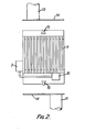
- a heat exhanger through separate channels of which inlet and outlet air respectively pass, the outlet air serving to warm the inlet air during operation of the - machine.
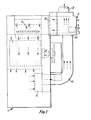
- the tumble dryer machine comprises a housing 1 attached to the rear of which is the heat exchanger 2 and control device 3 and within which are located, in the direction of air flow, a primary heat source 4, a rotatable perforated drum 5 and a fan 6.
- the drum 5 and the fan 6 are operated by a motor 7.
- ambient air is drawn through inlet 8 of the heat exchanger 2, along parallel inlet tubes 9 formed in the heat exchanger, through an opening 10 and over the heat source 4. From there the air passes through the perforated drum 5, where the air becomes moist, past the fan 6 and through a heat-resistant, flexible hose 11 to an opening 12 at the bottom of the heat exchanger.
- the air passes through parallel outlet tubes (not shown) of the heat exchanger to a heat-resistant, flexible exhaust hose 13 and from there to atmosphere.
- the heat exchanger is so arranged that substantially all of the inlet air passes therethrough.
- the inlet and exhaust tubes of the heat exchanger are arranged alternately and are preferably rectangular in cross section, having smooth uninterrupted surfaces, without ripples, indentations or projections such as rivets, to reduce the risk of blockage by lint and fluff.
- Each hose 11,13 is attached to a full-width cover plate 14 which is secured to the top or bottom of the heat exchanger by two quick-release clips 15.
- the plates 14 allow quick and easy access to the heat exchange tubes for cleaning.
- the heat exchanger works as follows.
- the hot, humid air enters the exchanger at opening 12, passes through the exchanger and exits to atmosphere.
- this exhaust air gives up part of its heat to the fresh air entering the tumble drying machine.
- This heat gain to the fresh air entering the machine causes it to-increase in temperature prior to it reaching the primary heating source 4; thus this fresh air is pre-heated.
- the primary heating source can be either a gas fired natural draught burner bar or bars, or a hot water or steam heating coil, or an electrical heating element.
- the tumble drying machines in which air entry to the drying drum is allowed on both sides of a common upstanding formation of drum case and in which the primary heat source is on one side only of this up-stand may have a blanking plate fitted to close off the air way from the side without heat source.
- the blanking or baffle plate results in increased velocity over the heat source and at the air port left open, which in turn provides a significant improvement in uniformity of temperature throughout the bulk of the air entering the drum 5.
- This improved uniformity in temperature provides increase of drying work per unit of entering air.
- this improvement of "work per unit of air” allows equal drying at reduced bulk of entering air. This reduction of total entering air quantity results in a corresponding reduction in the energy needed to raise the air temperature to the set point of the tumble drying machine's control thermostat.
- the baffle plate is an addition to improve machine performance and results in energy saving.
- the control device is provided to control the operation cycle of the machine and the control circuit is illustrated in Figure 3.
- the circuit illustrated is for a coin-operated machine, but could be adapted for other machines.
- the control device comprises a temperature sensitive device 16 which is preferably a single pole changeover thermo-disc switch.
- the switch is connected in the electrical circuit by live line part 17.
- Another live line part 17A, having common commencement point as line 17, is taken through a clock switch 18, operated by a coin feed mechanism (not shown) and connected to a terminal 19 and to the operating coil of a two pole changeover relay 22 of which ultimately all terminals are used.
- the operating coil of relay 22 has a connection to neutral.
- a centre changeover contact terminal 20 of relay 22 is connected through a door-operated switch 23 to the motor 7.
- a connecting line is provided from the door switch 23 to the other centre changeover terminal 24 of relay 22.
- centre changeover contact 24 is made to fixed contact 25, which in turn is connected through normally closed thermo switches 27-28-29 to gas valve 30.
- the motor 7 and the gas valve 30 have connections to neutral.
- the clock switch 18 opens and this de-energises the relay 22. Since switch 16 is closed, the motor 7 still operates, fed along line 17, through switch 16 to terminals 20,21 of relay 22, which is in the de-energised condition, and through door switch 23. Changeover terminal 24 breaks the contact with terminal 25 and contacts the terminal 26 and thus the gas valve or other heat source control 30 is closed to cut off heat source 4.
- the coin cycle time is reduced to 4/5ths.
- the over-run time available only after the second or third coin cycle, is approximately three minutes. It will be seen that single coin feeding a tumble drying machine fitted with the control device will not affect the overall drying cycle time, because no over-run can occur until the switch 16 has changed to the "hot" condition and that changeover, in practise, does not occur until the bulk of the drying work has been done.
- the saving of 1/5th of the machine time available through the coin clock is compensated for by the three minutes of over-run available on the last coin only.
- the overall drying time remains substantially unchanged, when compared to that for a standard tumble drying machine without press-dry cycle.
- meters 31, 32 Shown in broken line in Figure 3 are meters 31, 32 which allow monitoring of the time the tumble dryer is actually in work, fed by the electrical circuit through the coin operating mechanism, and separately the time the drum and fan have worked through the thermo disc switch 16 on over-run.
- Another meter 33 is provided to record the length of time the heat source has been in action. The results from these three recording meters allows complete analysis and record of the energy consumption of the machine. The machine coin take can also be recorded to allow accurate calculation of machine utilisation factors.
- the thermostat 27 is preferably of rod-type design and is preferably positioned directly in the exhaust air path after the exhaust air has left the fan 6, but before it enters the heat exchanger. If the air temperature reaches a predetermined high value, the thermostat 27 operates to interrupt electric supply to both switches 28 and 29, close the gas valve 30 and shut off heat source 4.
- Control and limit thermostats on standard tumble drying machines are very slow in action and have very high differential characteristics. These two weaknesses individually or in combination, allow excessive temperature over-run when the machines work on light work loads, or when the work load is an easy-dry material, such as nylon. Light, easy-dry materials such as nylon, are sensitive to excessive heat and can be burned or scorched in tumble drying machines with excessive temperature over-run.
- the additional rod type high temperature limit thermostat 27 reduces the risk of burning the work load. Also, because it is positioned in an easily accessible position and because the thermostat design allows adjustment of the "set point", this limit thermostat can be checked for operation and function in a very shorttime and with great ease. Because checking of this control is so simple and can be carried out without special equipment, in a very short time, it is practical and possible to make this checking operation part of the recommended routine preventive maintenance applied to tumble drying machines.
- thermostat 27 makes the tumble drying machines less of a fire risk generally, and less likely to destroy or damage some work loads.
- control device and heat exchanger could be provided as a unit for attachment to existing machines.
Landscapes
- Engineering & Computer Science (AREA)
- Textile Engineering (AREA)
- Drying Of Solid Materials (AREA)
Applications Claiming Priority (2)
| Application Number | Priority Date | Filing Date | Title |
|---|---|---|---|
| GB8031573 | 1980-10-01 | ||
| GB8031573A GB2088032A (en) | 1980-10-01 | 1980-10-01 | Tumble drying machines |
Publications (2)
| Publication Number | Publication Date |
|---|---|
| EP0049170A2 true EP0049170A2 (fr) | 1982-04-07 |
| EP0049170A3 EP0049170A3 (fr) | 1982-06-02 |
Family
ID=10516395
Family Applications (1)
| Application Number | Title | Priority Date | Filing Date |
|---|---|---|---|
| EP81304529A Withdrawn EP0049170A3 (fr) | 1980-10-01 | 1981-09-30 | Séchoir à tambour rotatif |
Country Status (2)
| Country | Link |
|---|---|
| EP (1) | EP0049170A3 (fr) |
| GB (1) | GB2088032A (fr) |
Cited By (4)
| Publication number | Priority date | Publication date | Assignee | Title |
|---|---|---|---|---|
| WO2009157698A3 (fr) * | 2008-06-27 | 2010-03-25 | 주식회사 대우일렉트로닉스 | Procédé de commande de la soupape à gaz d'un séchoir |
| US9080283B2 (en) | 2011-10-06 | 2015-07-14 | Whirlpool Corporation | Method to control a drying cycle of a laundry treating appliance |
| US9695544B2 (en) | 2012-04-02 | 2017-07-04 | Electrolux Home Products Corporation, N.V. | Dryer with air recirculation/heat exchange subassembly |
| EP3561174A1 (fr) * | 2018-04-25 | 2019-10-30 | Technisch Bureau Reinders B.V. | Installation et procédé de séchage de linge |
Families Citing this family (1)
| Publication number | Priority date | Publication date | Assignee | Title |
|---|---|---|---|---|
| JPH078691A (ja) * | 1993-06-24 | 1995-01-13 | Toshiba Corp | 衣類乾燥機 |
Family Cites Families (6)
| Publication number | Priority date | Publication date | Assignee | Title |
|---|---|---|---|---|
| US3859735A (en) * | 1974-01-23 | 1975-01-14 | Jr Herman E Katterjohn | Dryer preheater |
| US3882613A (en) * | 1974-05-20 | 1975-05-13 | Joseph M Wilson | Clothes dryer |
| GB1470163A (en) * | 1974-06-07 | 1977-04-14 | Ti Domestic Appliances Ltd | Tumbler dryers |
| US3959892A (en) * | 1974-08-01 | 1976-06-01 | A.M. Industries | Heated air recycle arrangement |
| US3969070A (en) * | 1975-02-12 | 1976-07-13 | Mcgraw-Edison Company | Clothes dryer with heat reclaimer |
| US4065253A (en) * | 1976-08-20 | 1977-12-27 | W. M. Cissell Manufacturing Company | Laundry dryer |
-
1980
- 1980-10-01 GB GB8031573A patent/GB2088032A/en not_active Withdrawn
-
1981
- 1981-09-30 EP EP81304529A patent/EP0049170A3/fr not_active Withdrawn
Cited By (6)
| Publication number | Priority date | Publication date | Assignee | Title |
|---|---|---|---|---|
| WO2009157698A3 (fr) * | 2008-06-27 | 2010-03-25 | 주식회사 대우일렉트로닉스 | Procédé de commande de la soupape à gaz d'un séchoir |
| CN102066648B (zh) * | 2008-06-27 | 2012-10-03 | 大宇电子株式会社 | 烘干机的气阀控制方法 |
| US9080283B2 (en) | 2011-10-06 | 2015-07-14 | Whirlpool Corporation | Method to control a drying cycle of a laundry treating appliance |
| US9695544B2 (en) | 2012-04-02 | 2017-07-04 | Electrolux Home Products Corporation, N.V. | Dryer with air recirculation/heat exchange subassembly |
| EP3561174A1 (fr) * | 2018-04-25 | 2019-10-30 | Technisch Bureau Reinders B.V. | Installation et procédé de séchage de linge |
| NL2020825B1 (nl) * | 2018-04-25 | 2019-11-05 | Technisch Bureau Reinders B V | Installatie en werkwijze voor het drogen van wasgoed |
Also Published As
| Publication number | Publication date |
|---|---|
| EP0049170A3 (fr) | 1982-06-02 |
| GB2088032A (en) | 1982-06-03 |
Similar Documents
| Publication | Publication Date | Title |
|---|---|---|
| US5443541A (en) | Dual element electrical clother dryer with single element interrupt circuit | |
| CA2185382C (fr) | Systeme de reglage de la temperature pour seche-linge | |
| US4842044A (en) | Furnace control system | |
| US3750304A (en) | Semi-recirculatory system for a clothes dryer | |
| EP0414231B1 (fr) | Dispositif de commande pour un équipement de ventilation | |
| GB2279448A (en) | Tumble dryer control | |
| EP0049170A2 (fr) | Séchoir à tambour rotatif | |
| DE3202586C2 (fr) | ||
| CA2364219C (fr) | Circuit de commande de secheuse | |
| US3806308A (en) | Gas dryer timer control circuit | |
| JP3234631B2 (ja) | 乾燥機 | |
| JP2000005493A (ja) | 衣類乾燥機の乾燥運転制御装置 | |
| KR0149033B1 (ko) | 의류건조기의 제어장치 | |
| US3170774A (en) | Humidity sensing control for a clothes drier | |
| EP0371263B1 (fr) | Dispositif de sécurité pour séchoirs à linge | |
| JP3263122B2 (ja) | 乾燥機 | |
| JPH02217746A (ja) | 瞬間湯沸器 | |
| GB2265705A (en) | Storage heater | |
| JP3234673B2 (ja) | 衣類乾燥機 | |
| JPH07112097A (ja) | 衣類乾燥機 | |
| JP3297302B2 (ja) | 衣類乾燥機 | |
| JPH07100298A (ja) | 衣類乾燥機 | |
| JP3254842B2 (ja) | 衣類乾燥機 | |
| JPH0780196A (ja) | 衣類乾燥機 | |
| GB2220471A (en) | Laundry dryers |
Legal Events
| Date | Code | Title | Description |
|---|---|---|---|
| PUAI | Public reference made under article 153(3) epc to a published international application that has entered the european phase |
Free format text: ORIGINAL CODE: 0009012 |
|
| PUAL | Search report despatched |
Free format text: ORIGINAL CODE: 0009013 |
|
| AK | Designated contracting states |
Designated state(s): BE DE FR IT NL SE |
|
| RHK1 | Main classification (correction) |
Ipc: D06F 58/28 |
|
| AK | Designated contracting states |
Designated state(s): BE DE FR IT NL SE |
|
| STAA | Information on the status of an ep patent application or granted ep patent |
Free format text: STATUS: THE APPLICATION IS DEEMED TO BE WITHDRAWN |
|
| 18D | Application deemed to be withdrawn |
Effective date: 19830508 |