EP0049602B1 - Wirbelablösender Strömungsmesser mit einer Ablösekörper-Messfühler-Einheit - Google Patents
Wirbelablösender Strömungsmesser mit einer Ablösekörper-Messfühler-Einheit Download PDFInfo
- Publication number
- EP0049602B1 EP0049602B1 EP81304534A EP81304534A EP0049602B1 EP 0049602 B1 EP0049602 B1 EP 0049602B1 EP 81304534 A EP81304534 A EP 81304534A EP 81304534 A EP81304534 A EP 81304534A EP 0049602 B1 EP0049602 B1 EP 0049602B1
- Authority
- EP
- European Patent Office
- Prior art keywords
- flowmeter
- unit
- flow
- vortex
- transducer
- Prior art date
- Legal status (The legal status is an assumption and is not a legal conclusion. Google has not performed a legal analysis and makes no representation as to the accuracy of the status listed.)
- Expired
Links
Images

Classifications
-
- G—PHYSICS
- G01—MEASURING; TESTING
- G01F—MEASURING VOLUME, VOLUME FLOW, MASS FLOW OR LIQUID LEVEL; METERING BY VOLUME
- G01F1/00—Measuring the volume flow or mass flow of fluid or fluent solid material wherein the fluid passes through a meter in a continuous flow
- G01F1/05—Measuring the volume flow or mass flow of fluid or fluent solid material wherein the fluid passes through a meter in a continuous flow by using mechanical effects
- G01F1/20—Measuring the volume flow or mass flow of fluid or fluent solid material wherein the fluid passes through a meter in a continuous flow by using mechanical effects by detection of dynamic effects of the flow
- G01F1/32—Measuring the volume flow or mass flow of fluid or fluent solid material wherein the fluid passes through a meter in a continuous flow by using mechanical effects by detection of dynamic effects of the flow using swirl flowmeters
- G01F1/325—Means for detecting quantities used as proxy variables for swirl
- G01F1/3259—Means for detecting quantities used as proxy variables for swirl for detecting fluid pressure oscillations
- G01F1/3266—Means for detecting quantities used as proxy variables for swirl for detecting fluid pressure oscillations by sensing mechanical vibrations
Definitions
- This invention relates to a vortex-shedding flowmeter, for measuring the flow rate of a fluid comprising;
- U.S. Patent (C) discloses a vortex-type flowmeter in which fluidic oscillations produced by a shedder mounted in a flow pipe are sensed by a downstream balanced-vane sensor pivoted in a torsional suspension that allows only microscopic vane motion.
- the shedder acts to divide the incoming fluid flowing therethrough and causes vortices to be shed alternately on either side thereof.
- the downstream train of vortices passing on either side of the vane sensor generates fluidic forces giving rise to alternate clockwise and counterclockwise torques, causing the sensor to oscillate mechanically at a frequency proportional to the flow rate of the fluid being metered.
- the oscillatory motion of the torsionally-supported sensor is detected by means of a transducer which takes the form of a strain gauge bonded to a resilient beam, one end of which is attached to the trunnion or shaft of the sensor projecting through the flow pipe, the other end being anchored.
- the resultant deformation of the beam as the shaft oscillates is translated by the strain gauge into a corresponding electrical signal whose frequency is indicative of flow rate.
- the transducer co-operates with an extension of the shaft on which the torsionally- - mounted sensor of the vortex meter is pivoted, the shaft extension having two flat parallel faces on opposing sides thereof.
- the transducer assembly is constituted by a first pair of parallel-connected piezoelectric elements lying in a common plane and interposed between one face of the shaft extension and a first pre-loading boick, and a second pair of parallel-connected piezoelectric elements lying in a common plane and interposed between the opposite face of the shaft extension and a second pre-loading block, the movement of the extension being restricted by the pre-loaded elements to a degree whereby the extension is virtually motionless.
- the two pairs of parallel-connected elements are connected to output terminals and are so polarized in relation to the faces in the shaft extension that alternate clockwise and counterclockwise torques cause the interconnected elements to generate an alternating voltage of the same frequency.
- the senor in each instance is torsionally mounted on a shaft projecting through a bore in the flow pipe, the free end of the shaft being operatively coupled to an external transducer to convert the oscillatory motion of the sensor into a corresponding electrical signal.
- the shaft therethrough is provided with an elastomeric seal made of neoprene or a material having similar elastomeric and physical properties.
- an eiastomeric seai functions effectively under normal operating conditions even when corrosive fluids are being metered which are either very hot or very cold, it is not an acceptable seal under extreme conditions.
- an elastomeric seal may break down under extremely high temperature operating conditions, such as those encountered with steam or liquid salts, or under extremely low temperature conditions involving cryogenic liquids such as liquid nitrogen or oxygen, or liquefied natural gas.
- the torsional mounting of the sensor in the vortex flowmeter is such as to link the sensor to an external transducer in a manner dispensing with the need for an elastomeric seal whereby the integrity of the flow pipe is maintained and the meter is capable of operating efficiently, even under extreme conditions.
- the senor is torsionally supported downstream behind the shedder on a pivot axis normal to the flow axis of the pipe, the torsional support including a torque tube whose base is received within a bore in the pipe and is welded thereto, the tip of the tube being welded to one end of the sensor to provide a closed structure preventing leakage of the fluid from the pipe.
- the flowmeter disclosed in my companion application is seal-less and thereby overcomes seal problems otherwise encountered under extreme temperature conditions. But because the meter has both a fixedly-mounted shedder and a torsionally-mounted sensor, one disposed behind the other in a flow pipe, the requirement for two bodies militates against the design of small-scale, low-cost meters of the simplest possible construction.
- the invention is preferably embodied in a seal-less meter having a torsional mounting which is of the type disclosed in my companion case wherein the linkage assembly for the external transducer dispenses with the need for elastomeric seals
- the invention is not limited thereto and is also applicable to arrangements of the types disclosed in my patents (A): (B) and (C), wherein the torsionally-mounted body is supported on journals or shafts extending through bores in the flow pipe, which shafts are provided with elastomeric seals.
- a significant advantage of the described flowmeters of the invention is that they make use of a torsionally-mounted combined shedder and sensor unit which lends itself to inclusion in small-scale, low-cost meters and yet essentially exhibits the operating characteristics and advantages of vortex-shedding meters having separate shedder and sensor bodies.
- the vortex-shedding flowmeter is capable of accurately measuring the flow-rate of a liquid or gas even under extreme operating conditions.
- the fluid to be metered is conducted through a flow pipe having a combined shedder and sensor unit torsionally supported therein on a pivot axis normal to the flow axis of the pipe, the torsional support including a torque tube whose base is received within a bore in the pipe and is welded thereto and whose tip is welded to one end of the combined shedder and sensor unit to provide a closed structure preventing leakage of fluid from the pipe.
- Fig. 1 schematically showing a first embodiment of a combined shedder and sensor unit of the invention
- the unit 10 which is shown in end view, has a trapezoidal cross section.
- the unit is torsionally-supported across a flow pipe 11 along a pivot axis which passes through the center of gravity CG of the unit, whereby the unit, which is. statically and dynamically balanced, is free to oscillate about this axis which is normal to the flow axis X of the flow pipe.
- unit 10 acts as an obstacle in the flow pipe and functions to divide the stream of incoming-fluid to be metered to produce vortices alternately on one side and then on the other side at a repetition rate proportional to the flow rate of the fluid.
- unit 10 acts as an obstacle in the flow pipe and functions to divide the stream of incoming-fluid to be metered to produce vortices alternately on one side and then on the other side at a repetition rate proportional to the flow rate of the fluid.
- moving trains of vortices are caused to travel on the left side and on the right side of the flow-pipe, these trains flanking the opposite sides of the unit
- Position A in Fig. 1 represents the condition existing at a particular moment in time when a vortex L, appears on the left side of unit 10 adjacent the leading edge thereof, and a vortex L 2 appears on the right side of the unit adjacent its trailing edge.
- Position B in Fig. 1 represents the condition which exists in the succeeding moment of time when the relationship of vortices L 3 and L 4 to the unit is reverse of that of vortices L, and L 2 . Since vortex L 3 produces a low pressure region at the right side, the resultant force F 3 is imposed on the left side against the leading edge of the unit and tends, therefore, to turn the unit about its pivot axis in the counterclockwise direction. And since vortex L 4 produces a low pressure region at the left side, the resultant force F 4 is imposed on the right side against the trailing edge of the unit and tends, therefore, to turn the unit in the counterclockwise direction, forces F 3 and F 4 being in cooperative relation.
- Unit 10 is mounted on very stiff torque tubes, as will later be described, or is otherwise torsionally-mounted so that it is highly resistant to movement and is only permitted to oscillate with a microscopic excursion in either direction such that at maximum deflection the movement of the unit away from its neutral position in either direction is no more than a small fraction of 0.03 mm (one mil).
- the unit therefore, effectively functions, in mechanical terms, as though it were rigidly mounted; for the microscopic motion thereof, though sufficient to excite a transducer to generate a flow rate electrical signal, is insignificant and will therefore not react adversely with the hydraulic vortex-shedding process.
- the integrated shedder/sensor unit 12 has a T-shaped cross section and is torsionally-supported within a flow pipe on a pivot axis which coincides with the center of gravity of this body and is normal to the flow axis X of the flow (not shown).
- the integrated shedder/sensor unit 13 has a triangular cross section, a clockwise movement being produced at position A and a counterclockwise movement at position B.
- torsional forces will be set up around all but cylindrical bodies having a round cross section.
- the invention is applicable to non-cylindrical combined shedder and sensor unit forms other than those shown in Figs. 1 to 3, such as those having a rectangular cross-sectional form.
- Torsionally-mounted sensors as explained in the above-identified copending applications, have excellent immunity to all forces other than those producing a torsional movement and therefore act to minimise noise signal resulting from vibratory and other extrinsic forces.
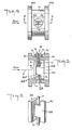
- a single body flowmeter of the vortex-shedding type of the invention is provided with a cylindrical flow pipe 14 having end flanges 14A and 14B.
- flow pipe 14 which serves as the body of the meter, is interposed in a process line carrying a liquid or gas whose flow is to be metered, the end flanges being bolted to the end flanges of the upstream and downstream pipes of. the line.
- an integrated shedder/sensor unit mounted transversely within flow pipe 14 is an integrated shedder/sensor unit, generally identified by reference numeral 15, having a rectangular plate leading section 15A whose broad front face looks towards the incoming fluid and whose rear face is joined at its center zone by an intermediate section beam 15B having a rectangular cross section to a rectangular bar tail section 15C whose width is the same as that of the beam and whose height is the same as that of the leading section.
- the unit is torsionally mounted on a pivot axis which coincides with its center of gravity and is perpendicular to the longitudinal flow axis X of flow pipe 10.
- the incoming flow stream which impinges on unit 15 is divided thereby, producing fluidic perturbations the form of a Karman vortex street.
- Unit 15 is pivotally supported by lower and upper torque tubes 16 and 17 which are attached to the intermediate section beam 15B, the torque tubes lying on the pivot axis.
- Lower torque tube 16 has its stepped base section 16A seated within and welded to a like- shaped bore in flow pipe 14 and its tip 16B welded to the lower edge of intermediate section 15B.
- Upper torque tube 17, as best seen in Fig. 5, is arranged so that its stepped base section 17a is received within a similarly-configured bore extending through the wall of flow pipe 14, the end of this base section being welded to the pipe.
- the tip section 17B of torque tube 17 is received within and welded to a socket formed in the upper edge of intermediate section 15B of the unit.
- the unit is operatively coupled to an external torque transducer, generally designated by numeral 18, by a link assembly which serves to transmit the torsional motion of upper torque tube 17 to torque transducer 18.
- This transducer is preferably a balanced piezoelectric structure of the type disclosed in copending application A.
- the transducer includes a pair of sub-assemblies each interposed between a stationary pre-loading block and a respective face of the rod extension 19 of the link assembly, each sub-assembly including a pair of piezoelectric elements in side-by- side relation.
- Rod extension 19 is coupled by a coupler 20 to a main rod 21 which extends into torque tube 17 and is anchored in the tip section of this tube and welded thereto.
- Coupler 20 is formed by a pair of cup-shaped flexible diaphragms in face-to-face relation whose circular flanges are welded together to define a cell similar to that of an aneroid barometer.
- Torque transducer 18 is seated on the annular upper section 22 of an isolator which is joined by a cylindrical intermediate section 23 to an annular lower section 24, coupler 20 - being disposed within the isolator.
- Lower section 24 is secured to flow pipe 14 by screwed clamps (not shown).
- Transducer 18 detects the motion of unit 15 as it oscillates about its pivot axis to produce a signal whose frequency is proportional to the flow rate of the fluid being metered.
- the torsional suspension of the unit effected by torque tubes 16 and 17 limits pivot motion at maximum torque to a microscopic motion in the order of a half micron in either direction from the neutral position; hence the unit is virtually motionless in operation.
- the torque tube must be strong enough to sustain internal flowmeter pressure and to withstand the forces generated at maximum fluid flow.
- the torque tube must be sufficiently stiff to impart to unit 15 a resonance frequency characteristic that is well above the maximum operating frequency of the meter in the anticipated range of fluid flow velocities. The reason for this latter requirement is that if the resonance frequency of the unit lies in the vicinity of the maximum operating frequency of the flowmeter. the unit will be excited into resonance, with highly disturbing effects on the output signal.
- torsiqnally-mounted unit 15 is in relatively close proximity to mounting flanges 14A and 14B of flow pipe 14.
- torsiqnally-mounted unit 15 is in relatively close proximity to mounting flanges 14A and 14B of flow pipe 14.
- the upper annular section 22 of the isolator is relatively thick and therefore stiff. But the cylinder intermediate section 23 and the annular lower section 24 are deliberately made relatively thin and flexible. As a consequence, any microscopic deflection of the flow pipe due to external forces would cause deflection of these sections and would impart a relatively modest force on the upper section 22 of the isolator on which transducer 18 is mounted. In this way, there is reduced transmission of vibratory forces to the transducer and the noise component in the signal generated thereby is cut down.
- the forces conveyed thereby to transducer 18 can be reduced to several orders of magnitude lower than those existing in the meter body.
- the effectiveness of the lower deflectable section 24 of the isolator may be enhanced by giving it a convoluted or corrugated diaphragm configuration to more effectively absorb the forces applied thereto.
- the isolator structure plays a role in the thermal characteristics of the meter sensing system; for the thin lower and intermediate metal sections 23 and 24 define an extended path of poor thermal conductivity between the body of the meter (i.e., flow pipe 14) and transducer 18 mounted on upper section 22. This path functions to effectively insolate the transducer from rapid temperature transients and makes it possible for the transducer to operate nearly at ambient temperature despite its closeness to the meter body.
- Coupler 20 in the sensor link assembly which intercouples main rod 21 to extension rod 19, functions as a torsional force coupling which minimizes the effects of bending and misalignment forces.
- the coupler serves to decouple and thereby attenuate bending forces set up in the sensor link assembly when torque tube 17 is bent by forces acting on unit 15, the coupler keeping these bending forces away from transducer 18.
- Coupler 20 also plays a role in the thermal characteristics of the sensing system. As in the case of the isolator, coupler 20 acts to extend the thermal conduction path between unit and transducer 18, and in this way isolates the transducer from rapid temperature transients.
- coupler 20 carries out an even more important function; for when rapid temperature changes occur in the flowmeter, torque tube 17 and the link assembly may then temporarily assume different temperature levels.
- the resultant differential expansion caused by the transitory temperature difference would, in the absence of coupler 20, give rise to large forces which would be exerted on transducer 15.
- the differential expansion caused by. a transitory temperature difference is largely absorbed by the coupling and therefore imposes no significant force on the transducer.
Landscapes
- Physics & Mathematics (AREA)
- Fluid Mechanics (AREA)
- General Physics & Mathematics (AREA)
- Measuring Volume Flow (AREA)
Claims (12)
Applications Claiming Priority (2)
| Application Number | Priority Date | Filing Date | Title |
|---|---|---|---|
| US06/192,351 US4339957A (en) | 1980-08-14 | 1980-09-30 | Vortex-shedding flowmeter with unitary shedder/sensor |
| US192351 | 1988-05-10 |
Publications (2)
| Publication Number | Publication Date |
|---|---|
| EP0049602A1 EP0049602A1 (de) | 1982-04-14 |
| EP0049602B1 true EP0049602B1 (de) | 1985-05-15 |
Family
ID=22709282
Family Applications (1)
| Application Number | Title | Priority Date | Filing Date |
|---|---|---|---|
| EP81304534A Expired EP0049602B1 (de) | 1980-09-30 | 1981-09-30 | Wirbelablösender Strömungsmesser mit einer Ablösekörper-Messfühler-Einheit |
Country Status (3)
| Country | Link |
|---|---|
| US (1) | US4339957A (de) |
| EP (1) | EP0049602B1 (de) |
| DE (1) | DE3170520D1 (de) |
Families Citing this family (17)
| Publication number | Priority date | Publication date | Assignee | Title |
|---|---|---|---|---|
| DE3241988A1 (de) * | 1981-11-10 | 1983-06-23 | Fuji Electric Co., Ltd., Kawasaki, Kanagawa | Durchflussmesser mit karman'scher wirbelstrasse |
| US4487076A (en) * | 1982-10-25 | 1984-12-11 | Fisher Controls International, Inc. | Vortex flow meter |
| EP0110321B1 (de) * | 1982-11-25 | 1988-09-07 | Oval Engineering Co., Ltd. | Wirbelströmungsmessgerät |
| US4884458A (en) * | 1986-10-20 | 1989-12-05 | Lew Hyok S | High sensitivity vortex shedding flowmeter |
| US4926695A (en) * | 1987-09-15 | 1990-05-22 | Rosemount Inc. | Rocking beam vortex sensor |
| US4884441A (en) * | 1988-05-11 | 1989-12-05 | Lew Hyok S | Variable capacity flowmeter |
| DE4122799A1 (de) * | 1991-07-10 | 1993-01-21 | Iwk Regler Kompensatoren | Vorrichtung zum messen der geschwindigkeit eines fluids |
| US5343762A (en) * | 1992-10-05 | 1994-09-06 | Rosemount Inc. | Vortex flowmeter |
| FR2717896B1 (fr) * | 1994-03-23 | 1996-06-07 | Schlumberger Ind Sa | Compteur de fluide à tourbillons comportant un double obstacle. |
| US7073394B2 (en) * | 2004-04-05 | 2006-07-11 | Rosemount Inc. | Scalable averaging insertion vortex flow meter |
| US6973841B2 (en) * | 2004-04-16 | 2005-12-13 | Rosemount Inc. | High pressure retention vortex flow meter with reinforced flexure |
| US7533579B2 (en) * | 2006-01-19 | 2009-05-19 | Invensys Systems, Inc. | Reduced bore vortex flowmeter having a stepped intake |
| BRPI0711496A2 (pt) * | 2006-06-05 | 2012-02-14 | 3M Innovative Properties Co | métodos para revestimento de uma junta de tubulação |
| JP5394506B2 (ja) | 2009-12-24 | 2014-01-22 | ローズマウント インコーポレイテッド | 渦振動センサプレートを持つ渦流量計 |
| US9599493B2 (en) * | 2014-10-31 | 2017-03-21 | Invensys Systems, Inc. | Split flow vortex flowmeter |
| CN108139258B (zh) * | 2015-12-09 | 2020-09-18 | 株式会社村田制作所 | 流体收纳装置 |
| RU2709430C1 (ru) * | 2019-05-30 | 2019-12-17 | Закрытое акционерное общество "Электронные и механические измерительные системы" (ЗАО "ЭМИС") | Датчик изгибающего момента для вихревых расходомеров |
Family Cites Families (8)
| Publication number | Priority date | Publication date | Assignee | Title |
|---|---|---|---|---|
| US1215135A (en) * | 1914-07-11 | 1917-02-06 | Gen Electric | Fluid-flow-indicating mechanism. |
| GB823684A (en) * | 1954-07-20 | 1959-11-18 | William George Bird | Improvements in or relating to apparatus for the measurement and integration of fluid-velocities |
| US3116639A (en) * | 1960-03-28 | 1964-01-07 | Savage & Parsons Ltd | Apparatus for the measurement and integration of fluid-velocities |
| US3927566A (en) * | 1971-06-17 | 1975-12-23 | Kent Instruments Ltd | Flowmeters |
| US3796096A (en) * | 1972-07-06 | 1974-03-12 | Airco Inc | Vortex flowmeter |
| US4196621A (en) * | 1975-11-20 | 1980-04-08 | National Research Development Corporation | Devices for detecting fluid flow |
| US4181020A (en) * | 1978-09-21 | 1980-01-01 | Fischer & Porter Co. | Vortex-shedding flowmeter having a sensing vane |
| DE2842556A1 (de) * | 1978-09-27 | 1980-04-10 | Siemens Ag | Geraet zum messen der geschwindigkeit einer stroemung |
-
1980
- 1980-09-30 US US06/192,351 patent/US4339957A/en not_active Expired - Lifetime
-
1981
- 1981-09-30 EP EP81304534A patent/EP0049602B1/de not_active Expired
- 1981-09-30 DE DE8181304534T patent/DE3170520D1/de not_active Expired
Also Published As
| Publication number | Publication date |
|---|---|
| EP0049602A1 (de) | 1982-04-14 |
| US4339957A (en) | 1982-07-20 |
| DE3170520D1 (en) | 1985-06-20 |
Similar Documents
| Publication | Publication Date | Title |
|---|---|---|
| EP0049602B1 (de) | Wirbelablösender Strömungsmesser mit einer Ablösekörper-Messfühler-Einheit | |
| EP0046649B1 (de) | Wirbelablösender Strömungsmesser mit einem an einem Torsionsrohr befestigten Torsionsmessfühler | |
| US4181020A (en) | Vortex-shedding flowmeter having a sensing vane | |
| US4550614A (en) | Oscillatory flowmeter | |
| US4791818A (en) | Cantilever beam, insertable, vortex meter sensor | |
| US4823614A (en) | Coriolis-type mass flowmeter | |
| US4831885A (en) | Acoustic wave supressor for Coriolis flow meter | |
| US4448081A (en) | Method and device for the dynamic and density-independent determination of mass flow | |
| US4297898A (en) | Stabilized vortex-shedding flowmeter | |
| US4069708A (en) | Flowmeter plate and sensing apparatus | |
| US4003253A (en) | Multi-range vortex-shedding flowmeter | |
| JP3233405B2 (ja) | 渦流量計 | |
| US4703659A (en) | Vortex shedding flow meter with noise suppressing and signal enhancing means | |
| US4262544A (en) | Torque-transducer for vortex-shedding flowmeter having torsional sensor | |
| EP0547577B1 (de) | Wirbelstrassen-Durchflussmesser mit zwei Sensorflügeln | |
| US4307619A (en) | Dual output vortex-shedding flowmeter having drag-actuated torsional sensor | |
| US4472022A (en) | Vortex flowmeter | |
| US4565098A (en) | Hybrid sensing system for vortex flowmeter | |
| US4226117A (en) | Vortex-shedding flowmeter having drag-actuated torsional sensor | |
| US4030355A (en) | Obstacle assembly for vortex type flowmeter | |
| US4003251A (en) | Acceleration-proof vortex-type flowmeter | |
| US4083240A (en) | Balanced sensing system for vortex-type flowmeter | |
| US4169376A (en) | External sensing system for vortex-type flowmeters | |
| US4445388A (en) | Dual-body vortex-shedding flowmeter | |
| AU600409B2 (en) | Trapped-vortex pair flowmeter |
Legal Events
| Date | Code | Title | Description |
|---|---|---|---|
| PUAI | Public reference made under article 153(3) epc to a published international application that has entered the european phase |
Free format text: ORIGINAL CODE: 0009012 |
|
| AK | Designated contracting states |
Designated state(s): DE FR GB |
|
| 17P | Request for examination filed |
Effective date: 19821011 |
|
| GRAA | (expected) grant |
Free format text: ORIGINAL CODE: 0009210 |
|
| AK | Designated contracting states |
Designated state(s): DE FR GB |
|
| REF | Corresponds to: |
Ref document number: 3170520 Country of ref document: DE Date of ref document: 19850620 |
|
| ET | Fr: translation filed | ||
| PLBE | No opposition filed within time limit |
Free format text: ORIGINAL CODE: 0009261 |
|
| STAA | Information on the status of an ep patent application or granted ep patent |
Free format text: STATUS: NO OPPOSITION FILED WITHIN TIME LIMIT |
|
| 26N | No opposition filed | ||
| PG25 | Lapsed in a contracting state [announced via postgrant information from national office to epo] |
Ref country code: FR Free format text: LAPSE BECAUSE OF NON-PAYMENT OF DUE FEES Effective date: 19870527 |
|
| PG25 | Lapsed in a contracting state [announced via postgrant information from national office to epo] |
Ref country code: DE Effective date: 19870602 |
|
| GBPC | Gb: european patent ceased through non-payment of renewal fee | ||
| REG | Reference to a national code |
Ref country code: FR Ref legal event code: ST |
|
| PG25 | Lapsed in a contracting state [announced via postgrant information from national office to epo] |
Ref country code: GB Effective date: 19881118 |