EP0049714B1 - Servomoteur à asservissement commandé par des moyens électro-magnétiques - Google Patents
Servomoteur à asservissement commandé par des moyens électro-magnétiques Download PDFInfo
- Publication number
- EP0049714B1 EP0049714B1 EP80108176A EP80108176A EP0049714B1 EP 0049714 B1 EP0049714 B1 EP 0049714B1 EP 80108176 A EP80108176 A EP 80108176A EP 80108176 A EP80108176 A EP 80108176A EP 0049714 B1 EP0049714 B1 EP 0049714B1
- Authority
- EP
- European Patent Office
- Prior art keywords
- pressure
- control
- piston
- control element
- servo drive
- Prior art date
- Legal status (The legal status is an assumption and is not a legal conclusion. Google has not performed a legal analysis and makes no representation as to the accuracy of the status listed.)
- Expired
Links
Images


Classifications
-
- F—MECHANICAL ENGINEERING; LIGHTING; HEATING; WEAPONS; BLASTING
- F15—FLUID-PRESSURE ACTUATORS; HYDRAULICS OR PNEUMATICS IN GENERAL
- F15B—SYSTEMS ACTING BY MEANS OF FLUIDS IN GENERAL; FLUID-PRESSURE ACTUATORS, e.g. SERVOMOTORS; DETAILS OF FLUID-PRESSURE SYSTEMS, NOT OTHERWISE PROVIDED FOR
- F15B9/00—Servomotors with follow-up action, e.g. obtained by feed-back control, i.e. in which the position of the actuated member conforms with that of the controlling member
- F15B9/02—Servomotors with follow-up action, e.g. obtained by feed-back control, i.e. in which the position of the actuated member conforms with that of the controlling member with servomotors of the reciprocatable or oscillatable type
- F15B9/03—Servomotors with follow-up action, e.g. obtained by feed-back control, i.e. in which the position of the actuated member conforms with that of the controlling member with servomotors of the reciprocatable or oscillatable type with electrical control means
-
- F—MECHANICAL ENGINEERING; LIGHTING; HEATING; WEAPONS; BLASTING
- F15—FLUID-PRESSURE ACTUATORS; HYDRAULICS OR PNEUMATICS IN GENERAL
- F15B—SYSTEMS ACTING BY MEANS OF FLUIDS IN GENERAL; FLUID-PRESSURE ACTUATORS, e.g. SERVOMOTORS; DETAILS OF FLUID-PRESSURE SYSTEMS, NOT OTHERWISE PROVIDED FOR
- F15B13/00—Details of servomotor systems ; Valves for servomotor systems
- F15B13/02—Fluid distribution or supply devices characterised by their adaptation to the control of servomotors
- F15B13/04—Fluid distribution or supply devices characterised by their adaptation to the control of servomotors for use with a single servomotor
- F15B13/042—Fluid distribution or supply devices characterised by their adaptation to the control of servomotors for use with a single servomotor operated by fluid pressure
- F15B13/043—Fluid distribution or supply devices characterised by their adaptation to the control of servomotors for use with a single servomotor operated by fluid pressure with electrically-controlled pilot valves
- F15B13/0436—Fluid distribution or supply devices characterised by their adaptation to the control of servomotors for use with a single servomotor operated by fluid pressure with electrically-controlled pilot valves the pilot valves being of the steerable jet type
Definitions
- the invention relates to an electromagnetically controlled servo drive with overrun control according to the type specified in the preamble of claim 1.
- a servo drive of this type in which the control piston designed as a control slide has an axially continuous pressure medium channel, which opens at one end in the high-pressure chamber of the housing and at the other end via radial bores of its piston shaft with a Drainage chamber of the housing is connected, while it is connected in the intermediate region via further radial bores to a control pressure chamber of the housing, the control pressure of which is controlled with the aid of the control element.
- the latter consists of a control sleeve which is axially displaceable in the discharge chamber on the shaft end and which controls the throttle cross section of the radial bores of the shaft with its control edge arranged at the sleeve end.
- the control sleeve has a fork shoulder with a relatively long axial holding rod, which is connected via a spring system to a fixed point outside the drain chamber.
- the magnetic device which consists of a regulator coil, surrounds the support rod and acts on the control sleeve via it.
- the known caster control with the control sleeve attached to the support rod leads to relatively large dimensions of the servo device and not least also due to the relatively large mass of the control sleeve together with fork and support rod to control inaccuracies, especially since the support rod must receive a sealing influencing its actuating movement if it is led out of the drain chamber to the external regulator coil.
- the sleeve-shaped control element forms the armature of the proportional magnet device, as a result of which a structurally simple and compact design of the servo device can be achieved, especially since the proportional magnet device surrounding the control element can also be incorporated into the housing in a space-saving manner.
- the control element as a whole is located within the control pressure chamber which carries the control pressure and is in a throttled connection with the associated housing connection. The control element is therefore pressure-balanced and low-friction. It is guided on the stem of the actuating piston. With these measures, high control accuracy can be achieved with a low inertia or a low hysteresis of the overrun control.
- control element does not have any support and anchor parts that extend out of the control pressure chamber, seals for such parts are also avoided.
- the actuating movements of the low-friction control element require relatively low actuating forces and therefore low electrical outputs.
- the magnetic adjustment of the control element is expediently carried out against a spring force. Precise travel paths can be achieved that are directly proportional to the strength of the magnetic field generated by an analog electrical signal.
- the shaft of the actuating piston has two axial pressure medium channels, one of which is connected to the high-pressure connection and the other to the low-pressure connection of the housing.
- This measure leads to a particularly simple configuration of the inner line connections with precise control of the openings of the two pressure medium channels by the control element, the control preferably being effected with the configuration of the control element and its control edges mentioned in claim 4.
- the control piston mentioned is expediently a differential piston which is acted upon by the high pressure on its smaller piston surface and by the control pressure in the control pressure chamber on its larger piston surface.
- the control element designed as an anchor and therefore consisting of ferromagnetic material expediently receives the coating mentioned in claim 6, for which a wear-resistant plastic material of known type with a self-lubricating effect is preferably used.
- the wall of the control pressure chamber can be used to guide the control element externally, but without exerting excessive transverse forces on the control element which could result in the control element sticking. This also results in a low-friction guidance of the control element.
- the outside diameter of the sleeve-shaped control element and the inside diameter of the magnetizable wall of the control pressure chamber are matched to one another in such a way that a certain magnetic air gap is present. It is achieved with the measure mentioned in claim 7 that even if the control element is adjusted slightly radially by magnetic forces acting in its transverse direction, there is a minimum air gap between the magnetic surfaces, as a result of which the disadvantageous effect of a zero air gap that leads to sticking of the control leads, is suppressed.
- the walls of the control pressure chamber can therefore be used to guide the control element without are exerted on the control element via these excessively large lateral forces.
- the stroke of the control element can advantageously be increased and the influence of the magnetic force acting in the transverse direction on the control element can also be reduced.
- the servo device according to the invention can be used for a variety of purposes. Preferred types of use are mentioned in claims 15 to 17.
- the invention provides a versatile servo device which can be reliably controlled by means of a low-power analog electrical signal and in which no moving part, possibly with the exception of the output shaft or the like, protrudes outwards from the housing.
- the device is characterized by its compact design and precise mode of operation with low-friction guidance of the control element.
- “High pressure” is understood in connection with the servo device according to the invention to mean any pressure medium pressure which is above atmospheric pressure and which, for. B. can range up to 210 bar and above. “Low pressure” means a pressure below high pressure up to atmospheric pressure, while “control pressure” means any pressure in the control pressure chamber that lies between high pressure and low pressure and which loads the actuating piston in order to perform the mechanical piston work.
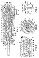
- electromagnetically controlled servo drive with follow-up control serving as a servo or servo motor has a housing consisting essentially of two parts, namely a piston housing H and a control element housing M.
- a differential piston is arranged as an actuator, which consists of an actuating piston P pressurized with pressure medium and a high-pressure piston Q.
- the differential piston comprising the two pistons P and Q is guided displaceably in the housing H and has an output shaft O.
- Shaft E is connected to the piston P and forms a control channel element.
- a control element C is mounted in the housing M so as to be displaceable, at least partially sealed, with respect to the shaft E.
- the control element C is adjustable in the housing M with the aid of a magnet coil S, which generates a magnetic field, the setting in certain setting positions being dependent on the excitation state of the magnet coil S.
- the piston housing H consists of a block or cylinder made of metal with a cylindrical Housing space with the cylindrical inner wall 10 and an axially aligned chamber with the smaller diameter chamber which is delimited by the cylindrical inner wall 11. At the transition between the coaxial spaces, a shoulder 12 is formed which forms a stop on the left for the piston P.
- the high-pressure piston Q slides with its outer surface 13 in sealing contact with the wall 11 and divides the chamber into a low-pressure chamber 15 on its right side and a high-pressure chamber 16 on its left side.
- the shaft O passes through an opening of a screw sleeve 17 and is in the Opening sealed by a seal 14.
- the screw sleeve 17 is screwed into the left end of the pressure chamber 16 and sealed by means of an O-ring 18.
- the actuating piston P slides with its peripheral surface 21 in a sealing arrangement against the cylindrical wall 10 of the housing H.
- the low-pressure chamber 15 is connected to a return or sump or the like via an outlet opening 24, which is also provided with an internal thread 25 for a connection fitting.
- the actuating piston P which forms the hydraulic working part, has a plurality of pressure compensation grooves 26 on its peripheral surface 21.
- the right piston surface 27 of the actuating piston P forms a pressure surface which faces the control pressure chamber 22, while the left piston side 23 is acted upon by the pressure in the low pressure chamber 15.
- the piston surface 23 has one or more radial grooves 29.
- the high-pressure piston Q serves to pretension the actuating piston P in the direction of the control pressure chamber 22.
- it has one or more pressure compensation grooves 32 on its circumferential surface 13 and is provided with an annular piston surface 33 acted upon by the high pressure in the high-pressure chamber 16 and one with the low-pressure chamber 15 facing piston surface 34.
- the piston Q is either formed in one piece with the actuating piston P or attached to it. The same applies to the arrangement of the shaft O or on the piston Q.
- the outer end of the shaft O can interact with any adjustable, switchable or controllable object.
- the cross-sectional area of the piston Q minus the cross-sectional area of the rod O is approximately equal to half the cross-sectional area of the actuating piston P.
- the control element housing M consists essentially of a pair of axially spaced magnetically active parts 40 and 41 and a magnetically ineffective part 42 lying between them, the two ends of which lie in sealing contact with the adjacent ends of the parts 50 and 41.
- the sealing connection can be made in different ways, e.g. by means of O-rings or, as shown, by the parts 40, 41 and 42 being jointed and soldered to one another.
- the parts 40, 41 and 42 form a continuously cylindrical channel 45 with a cylindrical wall 46.
- the channel 45 forms an extension of the control pressure chamber 22 of the control element housing H.
- the part 40 is screwed into the actuating piston housing H at 48 and sealed by means of an O-ring seal 49.
- the left end face 46 of this part 40 forms a right-hand stop for the actuating piston P, the piston path SP of which is therefore equal to the distance between the stop surfaces 12 and 46 minus the axial length of the piston P.
- the part 40 has a flange 50 in the vicinity of its left end, which projects radially into the channel 45 and forms a stop 51 on the left for the control element C.
- the right end of the channel 45 is closed by a cup-shaped screw plug 60, which is screwed into the part 41 and sealed off from it by an O-ring seal 61.
- the screw plug 60 can consist of a magnetically active or a magnetically ineffective material.
- the housing M and the part of the housing H which lies on the right side of the piston surface 27 of the piston P form the control pressure chamber.
- the part 40 of the housing M has a radially outwardly projecting flange 52 and the part 41 has a magnetically active ring 53 as a counter flange at an axial distance from the flange 52.
- the magnet coil S lies between these radial flanges 52 and 53.
- a sleeve 55 made of magnetically active material surrounds the magnet coil S and connects the two radial flanges 52 and 53 with an overlap therewith.
- the housing M accordingly forms a closed magnetic loop around the magnetic coil S, with the exception of a magnetic air gap which is formed by the magnetically ineffective intermediate part 42.
- the shaft E consists of a rod made of magnetically inactive material; it extends axially to the right from the right side of the piston surface 27 of the actuating piston P and is provided with a cylindrical outer surface 65.
- the shaft E can be integrally connected to the piston P or manufactured as a separate part and, e.g. shown in Fig. 5, connected to the piston.
- the outer diameter of the shaft E is at least approximately 6.35 mm; it is smaller than the inner ring area of the flange 50, so that the pressure medium has a free flow here when the actuating piston P moves together with the shaft E in the housing.
- the high pressure chamber 16 is connected to the control pressure chamber 22.
- the connection is effected via an axial pressure medium channel 70, which extends from the right end of the shaft E through the actuating piston P and the piston Q and is connected to the high-pressure chamber 16 via a radial channel 71.
- the channel 70 can be drilled into the control channel element E from the right end 72. It is closed here by means of a plug 73.
- the control pressure chamber 22 is also connected to the low pressure side. In the exemplary embodiment shown, this takes place via a second axial pressure medium channel 75, which extends from the right end of the shaft E through the actuating piston P and is connected behind the adjusting piston via a radial channel 76 to the low-pressure chamber 15.
- This channel 75 is also drilled from the right side into the control channel element E and is closed here by means of a plug 78.
- the shaft E has on its cylindrical outer surface a pair of circumferential grooves 80 and 81 arranged at an axial distance from one another (FIG. 3), which are separated by a web 82, the axial length of which is approximately equal to the stroke s of the actuating piston P.
- the groove 80 is connected to the high-pressure duct 70 via a radial duct 84, while the groove 81 is connected to the low-pressure duct 75 via a radial duct 86.
- the flanks 80 ', 80 "of the groove 80 cut the outer surface 65 of the shaft E at a sharp angle of preferably 90 °, as a result of which a sharp angle 87 is formed as the control edge.
- the groove 81 likewise has radial flanks 81' and 81", which form sharp angles 88 with the outer surface 65.
- the control pressure chamber 22 is accordingly connected to the high-pressure side and the low-pressure side via the grooves 80, 81 arranged on the outer surface 65 of the shaft E and arranged essentially identically, and via the aforementioned axial pressure medium channels 70 and 75.
- the actuating piston P and the shaft E are movable in the direction of the piston axis.
- the grooves 80 and 81 form inlet and outlet openings to and from the control pressure chamber 22. They point in a direction perpendicular to the direction of movement of the control element C.
- the control element C which is guided through the inner wall 46 of the housing part M, has the task of throttling the outflow of the pressure medium from the groove 80 forming the inlet opening and opening the flow of the pressure medium into the groove 81 forming the outlet opening and vice versa.
- the control element C consists of a sleeve, the cylindrical inner wall of which has a diameter such that there is a narrow gap or play f to the outer surface 65 of the shaft E.
- a control groove 90 is arranged essentially in the middle of the sleeve, which is connected to the outside of the sleeve via a pair of diametrically opposed radial channels 91.
- the radial channels 91 open into longitudinal grooves 93 on the outside of the sleeve, which lead to the sleeve ends.
- the control groove 90 preferably has an axial dimension, i. H. a width that is at least equal to the total stroke of the adjusting piston P.
- the groove width should be at least about 19 mm.
- the flank 90 'of the control groove 90 is located at a distance from the left end of the control element C which corresponds at least to the maximum adjustment path of the control element C to the right and at least the maximum stroke of the piston P.
- the two flanks 90 'and 90 "of the control groove 90 are at a distance which is slightly, for example 0.05 to 0.1 mm, smaller than the width of the web 82.
- the flanks 90' and 90" intersect the inner surface of the control element C rectangular, d. H. with formation of sharp control edges 94 and 96, which face the control edges 87 and 88 and form with these throttles 97 and 98, the throttle cross section of which changes with the actuating movement of the control element C relative to the shaft E.
- the control element C is a coil spring 95 with a small spring force of z. B. 0.9 kg to the left, which is supported with one end against the bottom surface of the screw plug 60 and with its other end against the right end of the control element C.
- the left end of the sleeve-shaped control element C is supported against a ring 99 made of magnetically inactive material, which in turn is supported on the right end face 51 of the flange 50.
- the ring 99 forms a magnetic air gap between the flange 50 and the control element C.
- One or more radial grooves 99 'in the surface lying against the flange establish a connection between the pressure chambers 45 and 22.
- the grooves 80 and 81 are spaced from the actuating piston P such that the web 82 is aligned with the control groove 90 when the control element C is in its left-hand neutral position shown.
- the pressure in the groove 90 and in the control pressure chamber 22 is approximately in the middle between the high pressure and the low pressure.
- the pistons P and Q are pressure balanced.
- the right end 100 of the sleeve-shaped control element is designed such that it tapers conically toward the sleeve end.
- the control element C has a clearance cx of 0.013 mm between its outer surface 103 and the inner surface 46 of the chamber 45, so that the control element can move radially in the control pressure chamber without any significant friction.
- the control element C consists of a magnetically active part with an outer diameter d and an outer coating 105 made of a magnetically inactive material with a thickness t which corresponds to at least twice the clearance cx, approximately 0.026 mm.
- the coating 105 can consist of any suitable, non-magnetic or magnetically ineffective material, such as copper, brass, stainless steel or the like.
- a plastic material, in particular “ Teflon” (trademark of the Du-Pont Corporation) or an equivalent plastic material with low friction properties is preferably used for this.
- the radial magnetic forces on the control element C designed as an armature act slightly eccentrically, so that the control element is adjusted radially by approximately its range of motion so that its outer surface lies against the wall 46 in a point or line shape. It is known that when two magnetically active surfaces are separated by a Ma magnetic field are drawn against each other, the magnetic forces increase to a maximum value after the asymptotic curve approaches the magnetic air gap towards zero. The ratio of the maximum air gap between the magnetically active surfaces to the lowest possible air gap is set so that it never exceeds the value 2: 1 by using the magnetically ineffective covering or coating 105 in the stated thickness.
- the radial forces acting between the outer surface of the control element C and the inner surfaces of the magnetically active parts 40 and 41 are limited in this way.
- the play f between the inner surface of the control element C and the outer surface 65 of the shaft E is preferably at least equal to the play cx in order to prevent the radial forces mentioned from pulling the control element C against the element E in frictional contact.
- the control element C is pressed against the spacer ring 99 and the stop 50 by the prestressing force of the spring 95.
- the grooves 80 and 81 are normally throttled by the same amount with respect to the control groove 90.
- the width or axial dimension of the. Groove 90 is preferably at least equal to the stroke of the piston P and the stroke of the control element C, so that the control groove 90 is always in connection with the groove 81, even when the control element C is in its extreme right position and the piston P in its extreme left position.
- channels 70 and 75 drilled into the rod-shaped shaft E can also be formed by concentrically nested tubes, the inner tube connecting the high pressure side and the annular space between the tubes connecting the low pressure side.
- the magnetic coil S of the proportional magnetic device preferably has a plurality of layers of copper wires which are encapsulated in an insulating medium. Their output wires 110x and 111x are led out through insulation in the sheath 55.
- Different types of electrical current sources can be used for the electrical power supply of the magnetic coil S, which supply the current required with regard to the number of coil turns. In some cases, it is appropriate to use an AC power source or a combination of an AC power source and a DC power source.
- the slight vibration of the resulting flow has a slight vibration effect on the control element C, which helps to suppress sticking or sticking of the control element and also to eliminate the hysteresis caused by the fixing of the control element.
- FIG. 4 schematically shows a current source 115x, which is an AC power source, a DC power source superimposed by an AC power source, or a DC power source, together with a potentiometer 116X, the outer connection 117X of which is connected to the one output of the current source via a lead wire 118X.
- the other terminal 119X of the potentiometer is led via a lead wire 120X and a variable resistor 121X and a lead wire 111X to the other output of the current source.
- the magnet coil S is connected to the potentiometer arm 126X via a lead wire 110X, while the other connection 127X of the magnet coil is connected to the lead wire 111X.
- the current flowing through the magnet coil S is changed from a minimum value determined by the resistor 121X to a maximum value determined by the resistance of the magnet coil S and the voltage of the current source.
- the current source could also consist of a computer or any other source with which an analog electrical signal can be applied to the magnetic coil S.
- the current flowing through the magnetic coil S generates a magnetic flux via the magnetically active part 40 to the likewise magnetically active control element C, which bridges the air gap formed by the part 105, to the magnetically active part 41.
- the control element C is pulled to the right against the restoring force of the spring 95, whereby the magnetic air gap is closed.
- variable resistor 121X maintains a slight bias current in the solenoid S when the potentiometer arm 126X is in the minimum excitation position shown, i.e. is in contact with the external connection 119X, so that the control element C is pulled to the right with a force which is slightly less than the lowest possible biasing force of the spring 95.
- the flow cross-section at the transition from the groove 80 to the control groove 90 is increased or decreased in relation to the actuating path, while the connection of the grooves 90 and 81 is changed in its cross section in the reverse sense.
- the interaction of the groove is comparable to a pair of variable valves or throttles which are connected in series between high pressure and low pressure, the control groove 90 forming an intermediate channel between the grooves and being under an intermediate or control pressure.
- the flow through a throttle is directly proportional to the throttle cross-section and the square root of the pressure drop across the throttle. Since the flow through two series-connected throttles is exactly the same, the pressure in the intermediate connection, i.e.
- the pressure in the groove 90 is transmitted to the control chamber 22 via the groove 99 '. It acts here in the sense of a displacement of the actuating piston P to the left with a force that is the pressurized area of the actuating piston P multiplied by the pressure height.
- the high pressure acts on the piston surface 33 of the high-pressure piston Q and thus on the actuating piston in the opposite direction. Since the piston surface 33 ⁇ m e.g. Is 50% smaller than the pressurized area of the control piston P, the high pressure exerts a force that tries to move the piston P to the right. If these forces plus or minus any external forces on the output shaft O are not balanced, the pistons move in the direction of the higher force until the state of equilibrium is established.
- each piston movement leads to a change in the connection of the two aforementioned throttles until the pressure in the control pressure chamber 22 exerts a leftward force on the piston surface 27 of the actuating piston which is exactly the same as the force , which the high pressure causes on the piston Q, plus or minus any forces acting on the shaft O from the outside.
- Fig. 1 shows the servo drive at maximum pressure of the pressure medium and with almost zero excitation current.
- the groove 80 is under high pressure and the groove 81 is under low pressure.
- the two grooves 80 and 81 are throttled by the same amount with respect to the control groove 90.
- the pressure drop from groove 80 to groove 90 and from the latter to groove 81 is therefore the same.
- the pressure in the groove 90 and in the control pressure chamber 22 is therefore exactly in the middle between the high pressure and the low pressure. Since the size of the piston surface 27, which includes the cross-sectional area of the control channel element E, is twice as large as the size of the piston surface 33, the pressure forces are balanced.
- the pistons P, Q and the stem E are therefore in their extreme left position.
- control element C moves into the left neutral position under the restoring force of the spring 95, the pistons P and Q automatically adjusting to the left position shown in FIG. 1.
- Fig. 5 shows a double-acting servo drive, the structure of which largely corresponds to that of FIGS. 1 to 3.
- Matching parts are given the same reference numerals, while functionally matching but structurally modified parts have the reference numerals of the exemplary embodiment according to FIGS. 1 to 3 provided with an index line.
- the shaft E ' is connected to the actuating piston P' in a radially movable manner in order to compensate for any misalignment of the two housing parts connected to one another.
- the left end 108 of the shaft E ' engages with play in a bore 107 at the right end of the actuating piston P' and is sealed in this bore by means of a soft-flexible pressure seal 110.
- the shaft E ' has an axial distance from its end 108 a flange 121 which also carries a soft-flexible pressure seal 111, which is in sealing contact with the inner wall of a counterbore.
- the left end 108 between these seals 110 and 111 has a circumferential groove 113 which is connected via a radial channel 114 to the left end of the channel 75 '.
- This groove 113 is connected via a channel 116, which is guided diagonally through the piston P ′, to the piston side 123 and thus to the part 115 of the low-pressure chamber 15.
- the left end 108 of the shaft E ' is secured in the bore 107 by means of a retaining ring 120 which is supported against a shoulder surface of the flange 121 and which in turn is held by a snap ring 124 which is seated in a groove in the piston bore.
- the flange 121 has an area which is twice as large as the end face 108. It is therefore pressure-balanced relative to the piston P '.
- magnet coils S and S ' also has a pair of axially spaced magnet coils S and S 'and a pair of magnetically inactive parts 42, 42' inside the magnet coils, between which there is a magnetically active part 43, which has a radial flange 43 'or the like is provided, which lies between the two mutually facing ends of the magnet coils S and S'.
- Both magnet coils S and S 'therefore each have a magnetic circuit which is closed by the control element C' on the magnetic air gap formed by the parts 42, 42 '.
- control element C ' corresponds to the control element C of FIG. 1 with the exception that its left end 100' is also conically tapered here.
- the magnetically active housing parts which lie on the side of the parts 42 and 42 'opposite the housing part 43, are counter-drilled with a diameter which is approximately 0.25 mm larger, in order to form shoulders on the left and right, the spacing of which is preferably approximately 0.25 mm is greater than the axial length of the control element C '.
- a slotted snap ring 128 is seated in a groove on the surface of this counterbore and forms a stainless steel support ring 129 for a spring 95 '.
- the snap ring 128 is arranged such that, taking into account the thickness of the support ring 129, the distance of the left surface 130 of the support ring from the shoulder is the same as the distance of the bottom surface of the pot-shaped screw plug 60 from the right shoulder.
- each of the two counterbores there is a support ring 132 or 133 which is movable in the counterbore in question and can be supported against the associated shoulder.
- the coil springs 95 and 95 'arranged on both sides of the control element C' press the support rings 132, 133 against the shoulders mentioned.
- the springs are preferably of the same design; they are under a low initial prestress of z. B. about 0.95 kg.
- control element C ' is adjusted by excitation of a solenoid coil, there is a small dead center in the movement of the control element before the excitation of the solenoid coil reaches a value at which this initial compressive force is overcome and the control element C' is adjusted.
- FIG. 5A shows schematically in a circuit diagram a current source for supplying power to the two magnetic coils S and S '.
- a potentiometer with a resistance element 142 is connected with its external connections via lines 141, 143 to the terminals of a battery 146 and to the two magnetic coils S, S '.
- the potentiometer arm 144 forming the tap is connected to the other two connections of the solenoid coils S, S 'via a line 145.
- the potentiometer arm 144 is set by springs (not shown) in a central position in which both magnet coils S, S 'are acted upon in the same way but with a minimum excitation current and with opposite magnetic polarity, so that they are the same on the control element C' but in opposite directions Apply directional forces that hold the control in its center or neutral position.
- the mode of operation of the magnetic coils S, S 'in cooperation with the control element C' corresponds essentially to the exemplary embodiment according to FIG. 1. If the magnetic coil S is excited more than the magnetic coil S ', the control element C' and with it the shaft E are adjusted 'and the control piston P' to the left. In the event of a power failure, the control element C 'comes into effect the spring 95, 95 'back to its neutral position shown. Since the springs 95, 95 'are under an initial pretension, the potentiometer arm 144 must be adjusted in one direction or the other over a small arc path before the magnetic force acting on the control element C' exceeds the initial pretension and triggers the actuating movement of the control element. In this way, a low zero or dead center is created in the control.
- a single-acting or a double-acting, electrically controllable and pressure-medium operated servo drive with overrun control is accordingly created, in which the only element which is led out of the pressure chamber is the shaft O.
- the position of this actuator can be easily controlled using an analog electrical current in the proportional solenoid device.
- the magnetic coils generate a magnetic force flow, under the effect of which the control element, which is located completely in the housing, is adjusted in relation to inlet and outlet channels which connect a control pressure chamber to the high-pressure side and the low-pressure side.
- the differential piston is controlled under the action of the differential pressures acting on it in such a way that it exactly follows the actuating movement of the control element.
- the piston is then held exactly in its position regardless of any changes in the external forces acting on the output shaft.
- FIG. 6 shows the electro-hydraulic servo drive according to FIG. 5 in connection with a remote-controlled slide valve.
- the latter comprises a combined valve and piston housing A, a housing B forming the control pressure chamber, an actuating piston N which actuates the slide D of the valve, a high pressure piston L, a stem K, a control element F and a pair of solenoid coils S, S ' which the control element F is adjusted either to the right or to the left and can thus be moved to the right or to the left via the actuating piston N of the slide D.
- the housing A has an elongated cylinder space 610 with the cylindrical inner wall 611, on which the actuating piston N is guided, and a plurality of housing chambers provided with inlets and separated by sealing webs, from right to left: a low-pressure chamber 613, a narrow housing web 614, an outlet inlet chamber 615, a wide housing land 616, an inlet pressure chamber 617, a wide housing land 618, an inlet and outlet chamber 619, a narrow housing land 620 and a low pressure chamber 621.
- the chambers all have the same axial width, while the wide housing lands have twice the width as the narrow housing bars.
- a cylinder chamber 625 Connected to the low-pressure chamber 621 is a cylinder chamber 625, the diameter of which is smaller than the diameter of the various housing webs and the chamber 610.
- the left end of the chamber 615 is closed by a plug screw 628 with the engagement of an O-ring seal 629.
- An inner channel 633 connects the low pressure chambers 621 and 613.
- the chamber 613 has an inlet opening 634 with an internal thread for the connection of a line fitting. Via the opening 634, the chamber 613 is normally connected to the low-pressure side or the return or a sump or the like.
- the chamber 615 has a housing opening 640 with an internal thread for a connection fitting, via which the connection to a pressure medium device to be actuated is established.
- the inlet chamber 617 is provided with an inlet opening 642 with an internal thread for a connection fitting and is connected to a pressure source which supplies a high-pressure medium with a constant volume.
- the chamber 619 has a connection 644 with an internal thread for a connection fitting and is connected via this connection to the other connection of the pressure-operated device.
- the slide D has a pair of cylindrical slide pistons 650 and 651, the axial spacing of which is equal to the distance between the two inlet-outlet pressure chambers and a length corresponding to the width of the chambers plus the width of a wide housing web.
- the slide piston 650 is either in contact with the housing web 614 or with the housing web 616, while the slide piston 651 is in contact either with the housing web 618 or with the housing web 620.
- the pistons 650 and 651 each have a pair of tapered, throttled channels 654, 655 at each end that deepen toward the piston end to maintain a constant inlet pressure and a limited fluid flow of e.g. B. 113 i / min through the valve.
- the inlet pressure changes within wide limits as the load on the controlled device changes.
- the grooves 654 and 655 are shown in FIG. 6 on the piston 650 in cross section and on the piston 651 in plan view.
- the high-pressure piston L is connected in one piece to the left end of the slide D and slides in a sealing arrangement on the wall of the chamber 625. It forms a high-pressure chamber 661 in this chamber, which is closed on the left by the screw plug 628.
- the slide has a tapered shaft 662 which forms a pressure medium channel which connects the chamber 619 to the low pressure side when the slide D is shifted to the right.
- the slide D is provided with a slide part 665 which is tapered in diameter and which forms a channel 666 which is connected to the housing space 610 and via which the chambers 615 and 616 are connected when the slide D moves to the left.
- the slide has a shaft portion 657 connecting the pistons 650 and 651 and tapering in diameter with a diametrical transverse channel 656, via which the inlet pressure in the chamber 617 is connected to an axial channel 658 which extends longitudinally through the slide D and a connection on the one hand to the high pressure chamber 661 and on the other hand to the right side of the slide D.
- the piston N is preferably connected in one piece to the slide D; it has a plurality of circumferential pressure compensation grooves 670 arranged at an axial distance and an axially extending groove 671 which intersects these and extends from the left piston surface 672 to the right piston surface 673.
- the intersecting grooves 671, 670 form a plurality of right-angled throttle points and, in cooperation, form a throttle channel which extends from the control pressure chamber to the low-pressure chamber, as will be described in more detail in connection with the exemplary embodiments according to FIGS. 7 and 8.
- the shaft K is connected to the piston N in the manner described in connection with FIG. Since the control pressure chamber is connected to the low-pressure side here via the throttle 671, only a single high-pressure connecting channel 675 needs to be provided in the shaft K here.
- This channel 675 extends axially through the shaft K up to a plug 676 at the right end thereof.
- a groove 678 on the outer surface 679 of the shaft K is connected to the axial pressure medium channel 675 via radially drilled openings 680.
- the groove 678 has radially standing flanks 678 'and 678 ".
- the control element F essentially corresponds to the control element C 'of FIG. 5. It has a circumferential groove 681 on its inner surface, which is connected via transverse channels 683 to a longitudinal groove 682 on the outside of the control element, so that the high-pressure medium in the inlet chamber 617 is connected to the control pressure chamber via the openings 656, the axial channel 658, the axial channel 675, the radial channels 680, the groove 678, the groove 681, the radial channel 683 and the groove 682.
- the groove 678 is arranged here in such a way that its right groove flank 678 "and the left flank of the groove 681 overlap slightly when the control element F is in its illustrated central position, in which the magnet coils S and S 'are not energized the overlap of these grooves depends on the throttling in the groove 671 leading to the outlet and the gap f (FIG. 3).
- the piston N moves the grooves relative to one another so that the flow through these grooves is equal to the flow through the groove 671 .
- the high pressure acting via the channel 658 in the high pressure chamber 661 acts on the right piston surface 660 of the high pressure piston L.
- the variable pressures in the control pressure chamber act on the left piston surface of the piston N.
- the piston N moves the groove 678 relative to the groove 681 in the sense opening or closing the connection of the channel 675 with respect to the connection leading to the low-pressure side until the pressure forces on the piston N and on the piston L of the valve slide D are in equilibrium.
- control element F returns to the neutral central position according to FIG. 6, as a result of which the slide D automatically returns to its neutral central position.
- the springs 95 and 95 ' are designed such that their free, unloaded length is greater than the installation length within the control device.
- the springs therefore exert an initial prestressing force on the two ends of the control element F via their support rings.
- the potentiometer arm according to FIG. 5A must therefore be adjusted over a small actuation path in order to excite one of the two solenoid coils more than the other before the actuating movement of the control element starts.
- the operator therefore has a slight dead travel in the manual control before the slide D is switched via the control element F to control an engine or piston.
- the valve described above is a two-way valve which can be remotely controlled by means of an analog electrical current and which permits very precise adjustment of the slide and accordingly precise control of the device which is controlled by the slide valve.
- FIG. 7 shows the device according to the invention in connection with a pressure relief or pressure relief valve of the differential piston type.
- This valve consists essentially of a valve housing T, a control housing U forming the control pressure chamber, a valve piston V, a control piston W, a shaft X, a magnetically actuated control element Y in the form of a sleeve and a solenoid S which can be connected to an adjustable current source to bring the control element into the different setting positions within the housing U depending on the excitation current.
- the housing T is formed from a block of steel, aluminum or another high-strength material and has an elongated cylinder space 710 in which the actuating piston W slides, in which the valve piston V is in turn displaceably mounted.
- the housing U corresponds to the housing part M of FIG. 1. It has a housing chamber 717 which is arranged coaxially with and in connection with the housing space 710 and has a cylindrical inner wall 716.
- the left side of the magnetically active part 740 forms a surface 716, which serves as a right stop for the piston W.
- the left end of the housing space 710 is counter-drilled at 720, the shoulder 721 forming a left stop for the reciprocating piston W.
- the axial length of the piston W is smaller by the distance d than the distance between the two abovementioned stops.
- an inlet opening 724 is provided in the axis of the housing space 710, in which sits a valve seat member 725, which has a cylindrical extension 726 lying in the inlet opening and sealed by an O-ring seal.
- the opening 724 forming the high-pressure connection is provided with an internal thread for a suitable connection fitting.
- the right end of the valve seat member 725 has a conical valve seat surface 731, which encloses an inlet opening 732 of the cylindrical extension 726 and against which a valve seat contact surface 734 lies at the left end of the valve piston V when the valve is closed.
- the valve seat contact surface 734 lies tangentially against the conical valve seat surface 731 on a circle 735, the diameter a of which is determined by the radius of curvature of the surface 734 and the cone angle of the surface 731.
- the dimensional ratios are selected so that the diameter a is at least larger than the diameter of the opposite end of the valve piston V, which is acted upon by high pressure, and the diameter of the part 726 of the valve seat member 725.
- the circle 735 encloses a surface against which the in pressure medium standing in the inlet opening exerts a rightward force which is equal to the pressure of the pressure medium multiplied by the size of this left surface.
- a housing outlet 740 is arranged on the housing with an internal thread for a connection fitting, which is connected to the chamber formed by the counterbore 720.
- the pressure at this housing opening 740 is zero.
- the actuating piston W has an outer diameter such that it slides in the sealing system with the cylindrical inner wall of the housing space 710. It is provided with a plurality of essentially rectangular, circumferential pressure compensation grooves 750, as is known per se. In addition, an axially extending rectangular groove 752 is provided on the outer surface of the piston, which intersects the circumferential grooves 750 and establishes a connection between the chamber 717 on the right side and the chamber 710 on the left side, which in turn connects to the housing outlet 740 is.
- the interfaces of the groove 750 and 752 create a throttle channel in the connection between the chamber 717 and the housing outlet 740 by means of a plurality of sharp-edged throttle points, so that the pressure drop of the pressure medium flowing through the throttle channel, largely independent of its viscosity, is proportional to the square root of the pressure difference between the pressure in the control pressure chamber 717 and the low pressure side formed by the housing outlet 740.
- the dimensions of the groove 752 are preferably chosen so that the leakage current is approximately in the order of 4 to 16.5 cm 3 / min. at maximum pressure at the valve.
- the circumferential grooves 750 have approximately dimensions of 0.5 mm width and 0.5 mm depth.
- the groove 752 carrying the leakage current has dimensions of approximately 0.75 mm width and 0.5 mm depth. It goes without saying that these dimensional relationships can fluctuate in order to achieve the desired flow rates and the desired pressure compensation.
- the piston W is provided with an inner cylindrical piston chamber 765, in which the right end 766 of the valve piston V is slidably guided and sealed by means of an O-ring seal 767.
- a radial flange 769 Near the left end of the valve piston V is a radial flange 769 which is in sliding contact with the cylindrical inner wall of the counterbore 720 of the housing space 710 and which is provided with axial grooves 771 for the passage of the pressure medium.
- the left end of the piston W is counterbored to form a shoulder 772 and a piston chamber 773 for receiving a valve spring 774.
- the spring 774 is supported on the one hand against the shoulder 772 and on the other hand against the flange 769.
- Spring 774 is the main pressure control member; it loads the valve piston V in the closing direction of the valve member and the piston W in the opposite direction.
- the valve piston V is provided with an axial channel 779, which connects the high pressure in the inlet opening 724 to the piston chamber 765 located on the right side of the valve piston V.
- the high pressure medium in the piston chamber 765 acts against the left side of the O-ring 767 via the gap between the piston part 766 and the inner wall of the piston chamber 765.
- the pressure medium therefore tends to move the O-ring 767 in a leftward direction on the valve seat 731.
- the cross-sectional area of the piston shaft 766 is smaller than the cross-sectional area of that of the circle 735 enclosed area, the area difference being designed such that the pressures in the inlet opening 724 tend to push the piston V to the right.
- the pressure spring 744 counteracts these pressures, and its spring tension can be variably adjusted by means of the adjusting piston W, which has a larger diameter.
- the shaft X projects coaxially from the piston W into the control pressure chamber 717.
- the actuating piston W which serves here as the control piston, and the shaft X are provided with a continuous axial channel 780, which is connected to the piston chamber 765 at the left end and with a transverse channel 782 ( 7A) is connected.
- the channel 782 opens into a cylindrical groove 783 on the outer surface 784 of the shaft X.
- the channels 782, 780 and 779 form an unthrottled connection between the interior 717 of the housing U and the pressurized housing inlet.
- the pressure in chamber 717 exerts a force on piston W to the left that is equal to the piston area of piston W minus the cross-sectional area of piston chamber 765.
- the control element Y essentially corresponds to that according to FIG. 1. It has an elongated, circumferential groove 790 on its inner surface, which is connected via a transverse channel 792 to a longitudinal groove 791 on the outer surface. As shown in FIG. 7A, the left flank 793 of the control groove 790 is at a distance from the left end of the control element Y, which corresponds at least to the greatest possible movement distance of the control element to the right, so that it overlaps the groove 783 when it is not under pressure Piston W is in the right end position shown, the degree of overlap of the groove 783 with, for example 0.12 mm is relatively small if the piston W has carried out its full piston travel to the left under the effect of the pressure in the pressure chamber 717.
- While most of the devices described here have an area ratio of the control piston area to the high-pressure piston area (differential area ratio) of about 2: 1, spring-loaded valves, such as pressure relief valves, pressure reducing valves, sequence valves and the like. Like., A spring force set before actuation.
- the net control pressure area is 7.5 times larger than the net area of the control piston which is exposed to the system pressure.
- the control element Y is constantly pressed to the left by the spring 795. There is therefore normally a partially throttled pressure medium flow into chamber 717 and a fully throttled pressure medium pressure from chamber 717.
- the high pressure acting on the inlet opening 724 generates a force directed to the right against the surface defined by the circumference 735 of the valve closing member.
- the high pressure is transmitted via the channel 779 into the piston chamber 765, where it acts against the end 796 of the valve piston V. Since the area 796 is smaller than the area enclosed by the circle 735, these forces attempt to move the valve piston V to the right.
- the spring 774 presses the valve piston V in the closing direction with a force which is dependent on its spring characteristic and the degree of its preload.
- the inlet pressure is also transmitted to control pressure chamber 717 via channels 779, 780, 782, grooves 783, 790, channel 792 and groove 791. This pressure then decreases via the throttle groove 752 and the groove 771 to the outlet 740.
- the pressure in the control pressure chamber 717 increases.
- the actuating piston W which is acted upon by the pressure in the control pressure chamber on the right-hand side of the piston, moves to the left and compresses the spring 774, whereby the closing force of the valve, i. the inlet pressure at which the valve piston V rises from the valve seat increases.
- the shoulder 721 limits the actuating movement of the piston W to the left and thus determines the amount by which the spring 774 can be compressed by the actuating piston.
- the maximum response pressure of the valve is determined in this way.
- the solenoid S When the solenoid S is excited, the magnetic flux moves the control element Y to the right against the force of the spring 795.
- the control element Y assumes different positions.
- the control element Y moves to the right, it throttles the outflow of the pressure medium from the groove 783, so that the amount of the pressure medium flowing into the control pressure chamber 717 becomes smaller than the amount of the pressure medium flowing out of the control pressure chamber 717 via the channels 752, 771.
- the actuating piston W therefore moves to the right under the force of the spring 774. This reduces the tension of the spring 774 and thus the pressure at which the valve piston V lifts off the valve seat under the differential pressure.
- the response pressure at which the valve opens can therefore be controlled via an analog electrical signal which is transmitted via an electrical line connection from any remote location.
- the tension of the spring 774 is adjusted within the given limits, as a result of which the response pressure can be set between a maximum operating value and a lower value depending on the spring constant of the spring 774 and the maximum stroke of the piston W.
- the pressure at the O-ring 767 also always acts in the direction of the valve seat in the valve according to the invention. This very high pressure tends to press parts of the O-ring into the gap between the surfaces to be sealed. The closing movement of the valve piston V therefore tends to lead the O-ring 767 out of the gap again, as a result of which the valve piston can return to the closed position with reduced friction.
- the tendency of the valve to release pressure medium even at pressures immediately below the response pressure is therefore suppressed and at the same time it is achieved that the valve closes under a smaller pressure difference after the response.
- the throttle groove 772 which cuts the circumferential groove 750 to form rectangular throttle edges, is particularly advantageous for realizing the throttle connection of the control pressure chamber with the outlet. Instead, other throttle channels can also be provided for this connection.
- the throttle connection 752, 750 there is the particular advantage that the flow rate is directly proportional to the square root of the pressure and at the same time largely independent of the viscosity of the pressure medium.
- the spring 795 shifts the control element Y to the left, with the result that the actuating piston W also shifts to the left, thereby compressing the spring 774.
- the piston W lies against the stop formed by the shoulder 721, so that the valve is set to the greatest possible response pressure in the event of a power failure. A reduction in the response pressure of the valve in the event of a power failure would in many cases lead to considerable operational hazards.
- the domed valve seat abutment surface 734 in conjunction with the conical valve seat surface improves the flow characteristic of the valve.
- This shape of the surfaces means that the influence of the eddy currents is completely suppressed when the valve is opened, so that the pressure-quantity curve is considerably flatter.
- This advantage is explained by the fact that when the valve is opened, the vortices form on the one hand with a smaller diameter than the diameter of the circle 735 (valve seat diameter) and on the other hand with a larger diameter than this.
- the vortex formation inside the actual valve seat takes place in an area of the piston which is under a lower pressure than the inlet pressure. If this eddy formation were not counteracted, the pressure-quantity characteristic of the valve would increase.
- there are surfaces here that have a larger diameter than the actual valve seat and on which dynamic vortex formation occurs without a static sealing effect the result is a flat pressure-quantity curve overall.
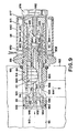
- the valve which is designed in the manner of a differential piston valve, essentially comprises a piston and valve housing T1, a control housing G forming the control pressure chamber, an actuating or valve piston I, a stem J as a control channel element, a magnetically adjustable control element K, and a solenoid S, by their excitation the control element K can be set in different positions in the housing T1.
- the housing T1 consists of a block made of steel, aluminum or another high-strength material which has a cylinder space 810 in which the piston I slides.
- the cylinder space 810 is counter-drilled at the right end and provided with an internal thread into which the threaded end 811 of the control housing G is screwed.
- the cylinder space 810 has a counterbore 812, which forms an outlet pressure chamber, and an adjoining counterbore 813, which forms a valve inlet channel or the high-pressure connection and is provided with a thread 814 for a connection fitting.
- valve seat member 814 Arranged in the counterbore 813 is a valve seat member 814 which is sealed by an O-ring 815 and which has a bearing flange 816 which surrounds the smaller counterbore 812.
- the valve seat member 814 is fixed by a snap ring 817 which is inserted into a groove on the inner wall of the counterbore 813.
- the valve seat member 814 has essentially the shape of a piece of pot open to the right side, the outer edge of which forms a circular valve seat 820.
- Several channels 821 connect the interior of the pot piece with the inlet side.
- the valve seat member 814 is made of a magnetically active material so that it can catch any magnetic dirt particles in the pressure medium.
- the counterbore 812 Immediately to the right of the valve seat member 814, the counterbore 812 has an outlet channel 830 with an internal thread for a connection fitting. Typically, the chamber formed by the counterbore 812 is at a low pressure, the pressure level of which is determined by the valve.
- the control housing G corresponds to the housing M of FIG. 1. Its left end face forms a right-hand stop for the piston I.
- the piston I consists of a cylindrical piston body sealingly sliding in the housing space 810, which in a known manner has a larger number of axially spaced circumferential pressure compensation grooves 841 are provided.
- a closing member 844 At the left end of the piston there is a closing member 844 with a valve seat contact surface 845, which tapers progressively tapering to the left, so that a concave conical surface results.
- the valve seat contact surface 845 When the valve seat contact surface 845 is moved to the right, the valve opening cross section therefore changes with respect to the linear stroke of the valve seat member after a falling, non-linear relationship.
- the shape of the valve seat contact surface 845 can be made for a specific pressure-operated device in such a way that leakage fluctuations of these devices are compensated for, in particular at low speed and with a temperature-related reduction in the viscosity of the pressure
- the diameter of the valve seat 820 is smaller than the piston diameter.
- the pressure medium acting on the piston I from the left exerts a force on the piston which is equal to the cross-sectional area of the valve seat 820 multiplied by the pressure.
- the stem J consists of a cylindrical rod which extends from the right-hand piston side 851 to the right and which has a circumferential groove 855 on its cylindrical outer surface 853 which is arranged on the stem J at an axial distance from the piston surface 851.
- the control element K essentially corresponds to the control element C according to FIG. 1.
- the groove 855 and a groove 890 on the inner wall of the control element K are arranged in the axial direction relative to one another in such a way that the grooves are a small amount of e.g. Overlap 0.13 mm when the control element K is in the extreme left position shown and the valve seat contact surface 845 is in contact with the valve seat 820.
- the piston I and the stem J have a continuous axial pressure medium channel 880 which is connected on the left side to the inlet 813 and on the right side to a transverse channel 882 which opens into the groove 855.
- the channels 880, 882 and the grooves 855, 890 as well as other aforementioned channels connect the high pressure side at the inlet 813 to the control pressure chamber.
- the high pressure acts on the right end surface of the stem J and on the annular piston surface 851.
- the total surface of these two piston surfaces is larger than the surface of the valve seat 820. As a result, the piston I is pressed against the pressure on its surface 844 in the closed position.
- the piston part 840 of the piston I forms a throttled connecting channel between the control pressure chamber and the outlet or the low-pressure chamber 812.
- this throttle connection is formed by a longitudinal groove 850 on the surface of the piston I, which cuts the grooves 841 to form rectangular control edges and connects the right piston side with the left piston side and the chamber 812 located here.
- the pressure medium flow and thus also the pressure drop change with the viscosity of the pressure medium flowing through the valve opening.
- some hydraulic pressure media such as oil in particular, the viscosity can change within relatively wide limits depending on the temperature.
- such changes in the viscosity of the oil e.g. B. in a temperature range of 20 ° C to 82 ° C, automatically compensated.
- the magnetic coil S and its magnetic circuit are designed in such a way that the control element K operates with relatively low electrical currents, e.g. less than 6 W. The heat generated by these currents is minimal.
- the valve is designed such that the solenoid S is kept at substantially the same temperature as the pressure medium which is controlled by the valve. In the exemplary embodiment shown, this is achieved in that the heat of the pressure medium is transferred to the magnetic coil and the latter is at the same time provided with thermal insulation in order to prevent the magnetic coil from cooling.
- the insulation can be provided by an air gap or air jacket or by a non-metallic insulating layer 896.
- the temperature of the solenoid S is changed accordingly due to the heat transfer via the metal of the piston housing R and the metal of the control pressure housing G.
- the temperature of the magnetic coil S is influenced more by the temperature of the pressure medium than by the current heat.
- the solenoid S consists, for example, of 1400 copper wire windings with a resistance at 20 ° C of about 24 m, which increases with temperature. With a fixed excitation voltage at the solenoid S, the current flow and thus the magnetic flux also decrease with increasing coil temperature. It follows that the control element K is adjusted to the left, which leads to a movement of the valve closing member in the closing direction. If the solenoid S receives considerably larger amounts of heat from the heat of the pressure medium than is generated by the heat of electricity according to the relationship 1 2 R, an almost complete temperature compensation can be achieved in the event of fluctuations in the operating temperature of the hydraulic pressure medium. By selecting the metals for the magnet coil wire, ie by using metals with a corresponding temperature resistance coefficient, a more or less large temperature compensation can be achieved.
- FIG. 9 shows a valve cartridge of the type according to the invention, which can be inserted as a unit in a line housing or the like, which has a high-pressure inlet channel and an outlet channel for the controlled pressure medium outlet in the interior.
- This inlet housing is indicated by dash-dotted lines and consists of a metal block with a cylindrical channel 910, the inner wall of which is designated 911.
- the channel 910 extends from the housing side 912 to a point where it is connected to a high pressure source.
- a cylindrical outlet channel 914 is also arranged in the housing and intersects the channel 910 at a distance from the housing surface 912.
- the channel 910 is provided with an internal thread 916 at its mouth, into which the valve cartridge can be screwed.
- the valve cartridge consists essentially of a piston housing AA, a housing BB forming the control pressure chamber, a valve actuating piston CC, a valve seat DD, a shaft FF, a control element GG and a solenoid SS, the excitation of which moves the control element GG to the right and according to the valve piston CC to the right, ie in the opening direction of the valve.
- the housing AA essentially consists of a block of high-strength magnetically active metal and has a cylindrical housing space with a cylindrical inner surface 920.
- the housing AA has an external thread approximately in the central area, with which the valve cartridge can be screwed into the internal thread 916 of the housing block.
- the screw connection is sealed by means of an O-ring seal 921.
- the cartridge housing AA reaches with its left end as far as behind the mouth of the outlet channel 914 into the channel 910 and is sealed here by means of an O-ring 922. Between the seals 921 and 922, the cartridge housing has radial openings 924, which establish the connection to the outlet channel 914.
- the valve seat member DD consists of a sleeve-like part made of magnetically active material; it is sealed at the left end of the chamber 919 of the valve cartridge and secured by a retaining ring 934.
- the control housing BB corresponds essentially to the control housing of the previous exemplary embodiments. It has a pair of magnetically active parts 970, 971 which are arranged at an axial distance from one another and are separated by a magnetically ineffective intermediate part 972. These parts are jointed and soldered together so that they form a pressure-tight housing.
- the parts 970, 971 and 972 together form an axial channel with a cylindrical inner wall 975. At the right end, this channel is closed by a cup-shaped screw plug 976, which is screwed into the part 971 and sealed by means of an O-ring 977.
- the plug 976 is also made of a magnetically active material.
- the magnetic coil SS encloses the parts 976, 970, 972 and 971 and is located in a housing jacket 980 made of magnetically active material, which is arranged between the outer surface of the material 976 and the cartridge housing AA, in an attachment thereto.
- the AA cartridge housing is also made of a magnetically effective material.
- the piston CC slides in a sealing arrangement on the inner wall 920 of the housing AA and has a plurality of circumferential pressure compensation grooves 940 arranged at an axial distance on the circumference.
- a valve seat contact surface 941 is arranged, the diameter of which is smaller than the diameter of the piston CC.
- the piston CC is provided with an axial longitudinal channel 964 which extends from its right piston surface 942 to an annular piston surface 965 and thus establishes the connection between the control pressure chamber and the outlet or low pressure.
- the left end of the channel 964 is tapered in diameter at 966 and forms a throttle point here.
- the shaft FF which extends to the right into the control pressure chamber, is arranged on the right piston surface 942.
- the piston surface 942 forms, together with the right end surface 943 of the shaft FF, a pressure surface for moving the piston CC to the left.
- the outer surface 944 of the shaft FF has a circumferential groove 945, which is connected via a radially drilled transverse channel 946 to an axial pressure medium channel 947, which extends from a location near the end surface to the left end 948 of the piston CC.
- Circumferential pressure compensation grooves 953 are also arranged in the surface 944 of the shaft.
- a plug 950 made of a magnetically active material is inserted into the right end of the channel 947 and has an axial channel 951. which is connected via a drilled transverse channel 952 to the high-pressure channel 910 and on the other hand to the channel 947 of the piston CC, so that the high-pressure medium stands on the groove 945.
- the left end face 948 of the plug 951 is in the outside seren edge area beveled to divide the impinging hydraulic fluid flow at this point and to steer in largely vortex-free flow towards the valve seat 932 when the valve is in the open state.
- the control element GG is approximately cup-shaped. It consists of a bottom surface 955 and a peripheral surface 956. The diameter of the inner bore is selected so that the control element GG slides sealingly on the outer surface 944 of the shaft FF. In this exemplary embodiment, the control element GG is slidably supported on the peg-shaped or rod-shaped shaft FF instead of on the inner wall of the control pressure chamber.
- the outer surface 958 of the control element GG has a diameter which is smaller than the diameter of the surface 920, so that a gap is formed here, via which the groove 945 is in pressure medium connection with the piston surface 942 of the piston CC.
- the walls of the pot piece forming the casing of the control element GG are provided with transversely drilled openings 960 which connect the space on the outside of the control element with the groove 945.
- the openings 960 intersect the right end of the groove 945 by an amount which corresponds to approximately half the diameter.
- the control element GG is pressed into the left position by a spring 962, which is supported on the one hand on the bottom of the pot-shaped plug 976 and on the other hand on the bottom of a bore 985, which is located at the right end of the control element GG.
- the bore 985 is connected to the interior of the control element via a small opening or throttle 986 in the base 955. This opening forms a damping opening which stabilizes the actuating movement of the control element GG with respect to the shaft FF.
- the magnetic coil SS is excited by the current source according to FIG. 1, a small current is produced in the coil, which generates a small magnetic flux which is not sufficient to adjust the control element GG against the initial force of the spring 982.
- the high pressure in the channel 910 is transmitted to the right side of the piston CC via the channels 952, 951, 947, 946 and the grooves 945 and 960. Since the right side of the piston is larger than the pressurized area of the valve seat 932, the piston CC is pushed to the left. Under all operating conditions there is a throttled pressure medium connection via these channels to the control pressure chamber and from here via the channel 964 and the throttle 966 to the outlet 914.
- the pressure medium volume is primarily determined by the size of the throttle 966.
- the pressure medium flowing out via the outlet 914 is e.g. supplied to a hydraulic device, wherein a certain pressure builds up in the outlet 914.
- the valve described maintains a constant differential pressure between inlet 910 and outlet 914. If this pressure gradient is to be increased or decreased, the solenoid SS is either energized or electrically switched off, as a result of which the control element GG either moves to the right or to the left and the valve closing element is adjusted in the closing direction or in the opening direction.
- the valve seat DD and the housings AA and BB are made of magnetically effective material.
- the excitation current in the magnet coil SS is sufficient to generate a magnetic field around the valve seat contact surface 941 and in the vicinity thereof. This magnetic field attracts magnetic particles that are carried along by the pressure medium throttled in the region of the channels 952 and deposits them in the vicinity of the valve seat 941. When the valve is opened, the deposited impurities are rinsed out.
- a two-part housing is provided, one housing part of which accommodates the working or actuator and has a high-pressure chamber, while the other housing part is the control housing forming a control pressure chamber.
- the housing parts can be made in one piece or consist of separately manufactured housings which are subsequently connected to one another in a pressure-tight manner.
- the working or actuator or the actuating piston has a surface acted upon by the pressure in the control pressure chamber and is movable in its housing under the pressure effect on this surface against forces acting in the opposite direction in positions which are precisely determined by a magnetically adjustable control element .
- the working or actuator can perform different functions, e.g.
- a stem or other actuator which is led out of the housing, further relax or compress a valve spring, actuate a valve slide, actuate a valve closing element which is connected to the actuator in one piece or consists of a separate part, move the piston of a pump back and forth or perform other operations that have a short stroke of e.g. less than 52 mm in one stroke direction with high lifting force.
- the two housing parts are manufactured separately and then connected to one another, an exact axial alignment of the two housing spaces can cause difficulties.
- the actuator is displaceable in one housing, while the control element moves in the other housing and tightly encloses the shaft. In the event of alignment difficulties the attachment of the shaft to the actuator shown in FIGS. 5 and 6 is recommended.
- valves In known electromagnetically controlled needle valves, relatively large electrical outputs are required to control even small amounts of hydraulic fluid, e.g. 12 watts for a pressure fluid quantity of at most 1.8 I / min. at 210 bar, which corresponds to a ratio of 24 watts per 3.7 I.
- the arrangement here is such that these valves are either fully open or fully closed.
- the maximum flow rate is so small that it can normally only be used to control another pressure-operated main valve, which in turn controls the larger amount of hydraulic fluid that is required by a controlled pressure-medium-operated device.
- the valve can control such large pressure medium volumes that the pressure medium can be used directly as an operating medium for actuating a powerful hydraulic device.
- the devices according to FIGS. 1 and 5 it is possible to move an actuator or the actuating piston back and forth by continuously changing the magnetic force on the control element C, C ', e.g. the potentiometer arm performs an oscillating movement, or one works with an oscillating permanent magnet enclosing the control chamber or by switching the switch of the solenoid shown in FIG. 1 on and off.
- the reciprocating piston movement can be achieved by switching over from one magnet to the other.
- the stroke movement of the actuating piston can e.g. be used to actuate a piston pump.
- the channel 75 can also be omitted and the high-pressure connecting channel 70 can be replaced by other means.
- the high-pressure chamber 16 provided with the inlet opening can be connected to the high-pressure side via a check valve.
- the outlet can be connected via a check valve to a device that is supplied by the pressure of the operating medium that is increased by the pressure of the high-pressure medium.
Landscapes
- Engineering & Computer Science (AREA)
- Physics & Mathematics (AREA)
- Fluid Mechanics (AREA)
- Mechanical Engineering (AREA)
- General Engineering & Computer Science (AREA)
- Servomotors (AREA)
- Magnetically Actuated Valves (AREA)
- Steering Control In Accordance With Driving Conditions (AREA)
Claims (18)
Applications Claiming Priority (3)
| Application Number | Priority Date | Filing Date | Title |
|---|---|---|---|
| US18991380A | 1980-10-02 | 1980-10-02 | |
| US189913 | 1980-10-02 | ||
| US20521480A | 1980-11-12 | 1980-11-12 |
Publications (2)
| Publication Number | Publication Date |
|---|---|
| EP0049714A1 EP0049714A1 (fr) | 1982-04-21 |
| EP0049714B1 true EP0049714B1 (fr) | 1986-04-23 |
Family
ID=26885598
Family Applications (1)
| Application Number | Title | Priority Date | Filing Date |
|---|---|---|---|
| EP80108176A Expired EP0049714B1 (fr) | 1980-10-02 | 1980-12-23 | Servomoteur à asservissement commandé par des moyens électro-magnétiques |
Country Status (4)
| Country | Link |
|---|---|
| EP (1) | EP0049714B1 (fr) |
| FI (1) | FI803795A7 (fr) |
| NO (1) | NO811257L (fr) |
| SE (1) | SE8101580L (fr) |
Families Citing this family (1)
| Publication number | Priority date | Publication date | Assignee | Title |
|---|---|---|---|---|
| US4561628A (en) * | 1983-08-31 | 1985-12-31 | Tokyo Keiki Company Limited | Electromagnetically operated hydraulic actuator |
Family Cites Families (10)
| Publication number | Priority date | Publication date | Assignee | Title |
|---|---|---|---|---|
| DE911686C (de) * | 1942-09-10 | 1954-05-17 | Asea Ab | Kolbenventil oder -schieber mit Hilfssteuerung |
| US2930360A (en) * | 1958-03-28 | 1960-03-29 | Yando Stephen | Servo mechanisms |
| DE1188398B (de) * | 1961-09-02 | 1965-03-04 | Siemens Ag | Elektrohydraulische Steuereinrichtung |
| FR1487472A (fr) * | 1966-05-26 | 1967-07-07 | Charbonnages De France | Distributeur hydraulique |
| DE2047525A1 (de) * | 1970-09-26 | 1972-03-30 | Kracht Pumpen Motoren | Steuerventil mit einem hydraulischen Verstellantrieb fur den Steuerkolben |
| DE2213439C3 (de) * | 1972-03-20 | 1978-12-07 | Robert Bosch Gmbh, 7000 Stuttgart | Elektrohydraulische Stelleinrichtung |
| DE2219929A1 (de) * | 1972-04-22 | 1973-10-31 | Teves Gmbh Alfred | Hydraulische servoeinrichtung fuer lenkungen in kraftfahrzeugen |
| DE2232566C2 (de) * | 1972-07-03 | 1984-08-09 | Garbe, Lahmeyer & Co Ag, 5100 Aachen | Hydraulische Wegeventileinheit |
| DE2461021A1 (de) * | 1974-12-21 | 1976-06-24 | Bosch Gmbh Robert | Vorrichtung zur steuerung wenigstens einer hydraulischen stelleinrichtung |
| US3943824A (en) * | 1975-01-22 | 1976-03-16 | Deere & Company | Hydraulic system |
-
1980
- 1980-12-05 FI FI803795A patent/FI803795A7/fi not_active Application Discontinuation
- 1980-12-23 EP EP80108176A patent/EP0049714B1/fr not_active Expired
-
1981
- 1981-03-12 SE SE8101580A patent/SE8101580L/ not_active Application Discontinuation
- 1981-04-10 NO NO811257A patent/NO811257L/no unknown
Also Published As
| Publication number | Publication date |
|---|---|
| SE8101580L (sv) | 1982-04-03 |
| FI803795L (fi) | 1982-04-03 |
| NO811257L (no) | 1982-04-05 |
| EP0049714A1 (fr) | 1982-04-21 |
| FI803795A7 (fi) | 1982-04-03 |
Similar Documents
| Publication | Publication Date | Title |
|---|---|---|
| DE69108805T2 (de) | Elektromagnetisches Solenoidventil mit einstellbarer Motorkraft. | |
| EP0294800B1 (fr) | Vanne pilotée hydrauliquement | |
| DE3406794C2 (fr) | ||
| EP0325958B1 (fr) | Clapet à commande hydraulique | |
| DE68915419T2 (de) | Proportional-Mehrwegeventil mit selbstregulierender Drucksteuerung. | |
| DE4244581A1 (de) | Elektromagnetisch gesteuerte Betätigungsvorrichtung | |
| DE3835705A1 (de) | Stossdaempfer zur daempfung von bewegungsablaeufen | |
| DE3901475C2 (de) | Fluidgesteuerte Servoanordnung | |
| EP0083688B1 (fr) | Soupape d'étranglement proportionnelle pilotée électro-hydrauliquement | |
| DE69004846T2 (de) | Hydraulik-Regelsystem. | |
| EP0103250B1 (fr) | Soupape de contrôle pour contrôle hydraulique | |
| DE3329734C2 (fr) | ||
| DE3224189A1 (de) | Hydraulisches system mit elektrischer proportionalsteuerung | |
| EP0100973B1 (fr) | Soupape proportionnelle pour commande de précision hydraulique | |
| DE3100582C2 (de) | Druck-Steuerventil | |
| DE2602844B2 (de) | Elektrisch gesteuertes Druckregelventil | |
| EP1253326B1 (fr) | Soupape pneumatique | |
| DE19643788A1 (de) | Elektrohydraulische Druckstellvorrichtung und Verfahren zur Umwandlung elektrischer Stellsignale in hydraulischen Stelldruck | |
| EP0049714B1 (fr) | Servomoteur à asservissement commandé par des moyens électro-magnétiques | |
| DE2513548B2 (de) | Einrichtung zur Steuerung der Fördermenge verstellbarer Axialkolbenpumpen | |
| EP0092064B1 (fr) | Dispositif pour commander un organe coulissant, en particulier un tiroir d'un distributeur | |
| EP0241870B1 (fr) | Dispositif de commande hydraulique | |
| DE2602381A1 (de) | Zweistufige stroemungsmengen-steuerventilanordnung | |
| DE3226809C2 (fr) | ||
| DE4214661A1 (de) | Elektrohydraulische stelleinrichtung |
Legal Events
| Date | Code | Title | Description |
|---|---|---|---|
| PUAI | Public reference made under article 153(3) epc to a published international application that has entered the european phase |
Free format text: ORIGINAL CODE: 0009012 |
|
| 17P | Request for examination filed |
Effective date: 19801229 |
|
| AK | Designated contracting states |
Designated state(s): DE FR GB IT NL |
|
| GRAA | (expected) grant |
Free format text: ORIGINAL CODE: 0009210 |
|
| AK | Designated contracting states |
Kind code of ref document: B1 Designated state(s): DE FR GB IT NL |
|
| PG25 | Lapsed in a contracting state [announced via postgrant information from national office to epo] |
Ref country code: NL Effective date: 19860423 Ref country code: IT Free format text: LAPSE BECAUSE OF FAILURE TO SUBMIT A TRANSLATION OF THE DESCRIPTION OR TO PAY THE FEE WITHIN THE PRESCRIBED TIME-LIMIT;WARNING: LAPSES OF ITALIAN PATENTS WITH EFFECTIVE DATE BEFORE 2007 MAY HAVE OCCURRED AT ANY TIME BEFORE 2007. THE CORRECT EFFECTIVE DATE MAY BE DIFFERENT FROM THE ONE RECORDED. Effective date: 19860423 Ref country code: FR Free format text: THE PATENT HAS BEEN ANNULLED BY A DECISION OF A NATIONAL AUTHORITY Effective date: 19860423 |
|
| REF | Corresponds to: |
Ref document number: 3071577 Country of ref document: DE Date of ref document: 19860528 |
|
| EN | Fr: translation not filed | ||
| NLV1 | Nl: lapsed or annulled due to failure to fulfill the requirements of art. 29p and 29m of the patents act | ||
| PLBE | No opposition filed within time limit |
Free format text: ORIGINAL CODE: 0009261 |
|
| STAA | Information on the status of an ep patent application or granted ep patent |
Free format text: STATUS: NO OPPOSITION FILED WITHIN TIME LIMIT |
|
| 26N | No opposition filed | ||
| GBPC | Gb: european patent ceased through non-payment of renewal fee | ||
| PG25 | Lapsed in a contracting state [announced via postgrant information from national office to epo] |
Ref country code: DE Effective date: 19880901 |
|
| PG25 | Lapsed in a contracting state [announced via postgrant information from national office to epo] |
Ref country code: GB Free format text: LAPSE BECAUSE OF NON-PAYMENT OF DUE FEES Effective date: 19881118 |