EP0050104A2 - A device in core barrels - Google Patents
A device in core barrels Download PDFInfo
- Publication number
- EP0050104A2 EP0050104A2 EP81850183A EP81850183A EP0050104A2 EP 0050104 A2 EP0050104 A2 EP 0050104A2 EP 81850183 A EP81850183 A EP 81850183A EP 81850183 A EP81850183 A EP 81850183A EP 0050104 A2 EP0050104 A2 EP 0050104A2
- Authority
- EP
- European Patent Office
- Prior art keywords
- core
- valve
- core barrel
- drill rod
- condition
- Prior art date
- Legal status (The legal status is an assumption and is not a legal conclusion. Google has not performed a legal analysis and makes no representation as to the accuracy of the status listed.)
- Ceased
Links
Images
Classifications
-
- E—FIXED CONSTRUCTIONS
- E21—EARTH OR ROCK DRILLING; MINING
- E21B—EARTH OR ROCK DRILLING; OBTAINING OIL, GAS, WATER, SOLUBLE OR MELTABLE MATERIALS OR A SLURRY OF MINERALS FROM WELLS
- E21B25/00—Apparatus for obtaining or removing undisturbed cores, e.g. core barrels or core extractors
- E21B25/02—Apparatus for obtaining or removing undisturbed cores, e.g. core barrels or core extractors the core receiver being insertable into, or removable from, the borehole without withdrawing the drilling pipe
-
- E—FIXED CONSTRUCTIONS
- E21—EARTH OR ROCK DRILLING; MINING
- E21B—EARTH OR ROCK DRILLING; OBTAINING OIL, GAS, WATER, SOLUBLE OR MELTABLE MATERIALS OR A SLURRY OF MINERALS FROM WELLS
- E21B21/00—Methods or apparatus for flushing boreholes, e.g. by use of exhaust air from motor
- E21B21/10—Valve arrangements in drilling-fluid circulation systems
-
- E—FIXED CONSTRUCTIONS
- E21—EARTH OR ROCK DRILLING; MINING
- E21B—EARTH OR ROCK DRILLING; OBTAINING OIL, GAS, WATER, SOLUBLE OR MELTABLE MATERIALS OR A SLURRY OF MINERALS FROM WELLS
- E21B25/00—Apparatus for obtaining or removing undisturbed cores, e.g. core barrels or core extractors
Definitions
- the present invention relates to a device in core drilling for indicating when a core barrel in a rotatable outer hollow drill rod is no longer capable oCaccmmodating any more drilled core materialo
- a known device for accomplishing said indication includes an annular elastic valve, mounted between two parts in the core barrel which are axially displaceable in relation to each other, of which the one, i.e. the portion accommodating the core is displaced towards the other portion axially fixed in the hollow drill rod when the core barrel is full or when a core blockage has occurred.
- the valve is compressed and thereby expands radially so that its annular cylindrical surface presses sealingly against an annular inner surface of the drill rod.
- This seal results in that flushing medium, which is forced down the drill rod string and which is used, inter alia, for cooling and flushing the bit attached to the bottom of the drill rod, cannot pass the space between the rod bore and the core barrel, whereby the pressure of the flushing medium above the seal increases.
- This pressure increase can be read on a gauge mounted on the drill rig and constitutes said indication.
- the known device described above has been found to function satisfactorily if complete control can be maintained over the flushing medium pressure and core blockages, but is unsuitable to use if drilling is done without this control, since the bit is rapidly burnt out in such cases when the supply of flushing slurry to it ceases, and the rig operator does not immediately notice that the gauge pressure has increased.
- Another drawback with the known device is that its valve can be subjected to such a large compressive force that it is destroyed and must be exchanged, which is both time- consuming and expensive.
- the object of the present invention is to provide a device of the kind described in the introduction, by means of which the drawbacks of previously known devices are circumvented.
- the primary advantage with the inventive device is that a sufficiently large amount of flushing medium is supplied to the drill bit for preventing its being burnt out, even after the core barrel is filled or a core blockage has occurred and drilling continues, in spite of the gauge indication that the flushing medium pressure has increased to an unacceptable level.
- Another advantage is that the valve included in the device can never be loaded (compressed together) so that it is permanently deformed or otherwise destroyed.
- the pressure to which the valve can at most be subjected is settableo This setting facility signifies that the radial distance between the valve and the drill rod bore can be varied, and even reduced so that the flushing passage is completely closed, which can be desirable in some applications.
- the core barrel illustrated in Figures 1 and 2 and generally denoted by the numeral 1 comprises an upper portion 1a, which is rotatable together with the drill rod 2, and a lower part 1b which does not rotate relative the drill rod and which is intended to accommodate a drilled core.
- the rod 2 forms the bottom section of a rotating drill rod string usually comprising several rods, which are connected to a drill rig of a conventional kindo
- the rod 2 is also of conventional embodiment, inter alia with a bit 3 and a recess which, via gripping jaws 5 rotatably mounted in the upper part 1a of the core barrel, prevent the latter from being displaced upwards inside the rod 2 from the working position illustrated in the figures.
- the bottom portion of the core barrel 1 is also of conventional implementation with a core collecting sleeve 6 and a core catching sleeve 7.
- the bottom portion 1b of the barrel 1 is conventionally rotatably connected to the upper part 1a by means of a ball bearing arrangement 8.
- the upper part 1a includes a body 9 carrying the gripping jaws 5, a shaft 10 in threaded connection with the body 9, a lock nut 11 provided with flushing medium ducts 11a, said nut locking the shaft 10 to the body 9 and also limiting the depth to which the barrel can be sunk in the drill rod, and a washer 12 displaceably mounted on the shaft 10 and engaging against the nut 11.
- the part 1a also includes a sleeve 26 coating with the ball bearing arrangement 8 and connected to a sleeve 13 surrounding a portion of the shaft 10 and an extension 10a thereof.
- a pack 19 of Bellville washers is inserted between a washer 14 and a washer 15, glidably mounted on the extension and engaging against a sleeve 16, which in turn engages against a washer 17 retained on the extension by a nut 18.
- the spring pack urges with a predetermined force, which can be varied by inserting different numbers of Bellville washers between the washers 14 and 15, the bottom part 1b of the core barrel 1 downwards in Fig. 2 via the washer 15, which is urged against a shoulder 20 on the sleeve 13, the latter being axially rigidly connected, via the sleeve 26, to the portion of the bottom part 1b shown in Fig. 2.
- the sleeve 13 is threaded onto a sleeve 21 partially surrounding a shaft 10, the lower end of said sleeve being provided with recesses 21 and engaging against the washer 14, while being non-rotatably fixed to the shaft by means of a locking pin 22 attached to the shaft 10 and projecting into the recesses 21a.
- an elastic ring 23 forming a valve, the function of which will now be described in conjunction with the description of the function of the device in accordance with the invention.
- Flushing medium is forced down into the drill rod string during drilling and passes between the bore of the rod 2 and the core barrel 1 before it reaches the bit 3.
- the part 1b of the barrel has taken up a maximum length of core material, or when a core blockage occurs, the part 1b is pressed upwards relative the upper part 1a, which cannot be displaced upwards in the rod 2 due to the gripping jaws 5 end shoulder 4.
- This upward pressure takes place against the action of the force in the spring pack 19, which is thus compressed, and against the action of the force in the ring 23 which is also compressed.
- the compression of the spring pack 19 and ring 23 is however limited by an annular recess 24 on the sleeve 13, being brought into engagement against the washer 14, after about 4 millimeters' compression of the spring pack, and therefore also after about 4 millimeters' compression of the ring 23.
- the ring 23 can never be compressed so that it is permanently deformed or otherwise destroyed.
- the distance between the washer 12 and the sleeve 21 can be varied, which is done by screwing the locking nut 11 a short distance away from the body 9 when the core barrel has been taken up from the string, after which the body is turned relative the shaft 10 until the body assumes a position relative the shaft corresponding to the desired distance.
- the lock nut 11 can subsequently be tightened once again. After having loosened the lock nut 11, the body 9 can be screwed off the shaft 10, if so desired, and be removed from the shaft together with the lock nut and washer 12, after which the ring 23 can be removed and exchanged for another ring.
Landscapes
- Engineering & Computer Science (AREA)
- Geology (AREA)
- Life Sciences & Earth Sciences (AREA)
- Mining & Mineral Resources (AREA)
- Physics & Mathematics (AREA)
- Environmental & Geological Engineering (AREA)
- Fluid Mechanics (AREA)
- General Life Sciences & Earth Sciences (AREA)
- Geochemistry & Mineralogy (AREA)
- Mechanical Engineering (AREA)
- Processing Of Stones Or Stones Resemblance Materials (AREA)
- Earth Drilling (AREA)
- Soil Working Implements (AREA)
Abstract
A device in core drilling for indicating when a core barrel placed in a rotatable hollow drill rod is no longer capable of receiving a further quantity of reamed-out core material includes a valve which at said condition of the barrel constricts the passage for flushing medium flowing between the core barrel and the bore of the drill rod so that a readable flushing medium pressure increase occurs. The valve closes off said passge incompletely to allow a minor quantity of flushing medium to be taken to the drill bit mounted at the bottom of the drill rod, thereby to prevent said drill bit from being burnt out.
Description
- The present invention relates to a device in core drilling for indicating when a core barrel in a rotatable outer hollow drill rod is no longer capable oCaccmmodating any more drilled core materialo
- It is already known to indicate to a core drill operator when a core barrel has been filled with core, or when a so- called core blockage occurs. When the operator in question receives this indication, drilling must be broken off and the core barrel taken up out of the drill rod.
- A known device for accomplishing said indication includes an annular elastic valve, mounted between two parts in the core barrel which are axially displaceable in relation to each other, of which the one, i.e. the portion accommodating the core is displaced towards the other portion axially fixed in the hollow drill rod when the core barrel is full or when a core blockage has occurred. At this displacement, the valve is compressed and thereby expands radially so that its annular cylindrical surface presses sealingly against an annular inner surface of the drill rod. This seal results in that flushing medium, which is forced down the drill rod string and which is used, inter alia, for cooling and flushing the bit attached to the bottom of the drill rod, cannot pass the space between the rod bore and the core barrel, whereby the pressure of the flushing medium above the seal increases. This pressure increase can be read on a gauge mounted on the drill rig and constitutes said indication.
- The known device described above has been found to function satisfactorily if complete control can be maintained over the flushing medium pressure and core blockages, but is unsuitable to use if drilling is done without this control, since the bit is rapidly burnt out in such cases when the supply of flushing slurry to it ceases, and the rig operator does not immediately notice that the gauge pressure has increased. Another drawback with the known device is that its valve can be subjected to such a large compressive force that it is destroyed and must be exchanged, which is both time- consuming and expensive.
- The object of the present invention is to provide a device of the kind described in the introduction, by means of which the drawbacks of previously known devices are circumvented.
- This object is achieved by the apparatus in accordance with the invention being given the characterizing features disclosed in the claims.
- The primary advantage with the inventive device is that a sufficiently large amount of flushing medium is supplied to the drill bit for preventing its being burnt out, even after the core barrel is filled or a core blockage has occurred and drilling continues, in spite of the gauge indication that the flushing medium pressure has increased to an unacceptable level. Another advantage is that the valve included in the device can never be loaded (compressed together) so that it is permanently deformed or otherwise destroyed. A still further advantage is that the pressure to which the valve can at most be subjected is settableo This setting facility signifies that the radial distance between the valve and the drill rod bore can be varied, and even reduced so that the flushing passage is completely closed, which can be desirable in some applications.
-
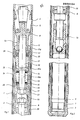
- Fig. 1 is a sectional side view of the upper part of a core barrel including the inventive device, and assuming a working position in a drill rod string, and
- Fig. 2 is a sectional side view of the lower portion of the core barrel and the bottom of the drill rod string in Fig. 1.
- The core barrel illustrated in Figures 1 and 2 and generally denoted by the
numeral 1 comprises anupper portion 1a, which is rotatable together with thedrill rod 2, and alower part 1b which does not rotate relative the drill rod and which is intended to accommodate a drilled core. Therod 2 forms the bottom section of a rotating drill rod string usually comprising several rods, which are connected to a drill rig of a conventional kindo Therod 2 is also of conventional embodiment, inter alia with abit 3 and a recess which, via grippingjaws 5 rotatably mounted in theupper part 1a of the core barrel, prevent the latter from being displaced upwards inside therod 2 from the working position illustrated in the figures. The bottom portion of thecore barrel 1 is also of conventional implementation with acore collecting sleeve 6 and a corecatching sleeve 7. - The
bottom portion 1b of thebarrel 1 is conventionally rotatably connected to theupper part 1a by means of a ball bearingarrangement 8. Theupper part 1a includes abody 9 carrying thegripping jaws 5, ashaft 10 in threaded connection with thebody 9, alock nut 11 provided with flushingmedium ducts 11a, said nut locking theshaft 10 to thebody 9 and also limiting the depth to which the barrel can be sunk in the drill rod, and awasher 12 displaceably mounted on theshaft 10 and engaging against thenut 11. Thepart 1a also includes asleeve 26 coating with the ball bearingarrangement 8 and connected to asleeve 13 surrounding a portion of theshaft 10 and anextension 10a thereof. Apack 19 of Bellville washers is inserted between awasher 14 and awasher 15, glidably mounted on the extension and engaging against asleeve 16, which in turn engages against awasher 17 retained on the extension by anut 18. The spring pack urges with a predetermined force, which can be varied by inserting different numbers of Bellville washers between thewashers bottom part 1b of thecore barrel 1 downwards in Fig. 2 via thewasher 15, which is urged against ashoulder 20 on thesleeve 13, the latter being axially rigidly connected, via thesleeve 26, to the portion of thebottom part 1b shown in Fig. 2. - At its upper end illustrated in Fig. 1, the
sleeve 13 is threaded onto asleeve 21 partially surrounding ashaft 10, the lower end of said sleeve being provided withrecesses 21 and engaging against thewasher 14, while being non-rotatably fixed to the shaft by means of alocking pin 22 attached to theshaft 10 and projecting into therecesses 21a. Between thesleeve 21 andwasher 12 there is inserted anelastic ring 23, forming a valve, the function of which will now be described in conjunction with the description of the function of the device in accordance with the invention. - Flushing medium is forced down into the drill rod string during drilling and passes between the bore of the
rod 2 and thecore barrel 1 before it reaches thebit 3. When thebottom part 1b of the barrel has taken up a maximum length of core material, or when a core blockage occurs, thepart 1b is pressed upwards relative theupper part 1a, which cannot be displaced upwards in therod 2 due to the grippingjaws 5end shoulder 4. This upward pressure takes place against the action of the force in thespring pack 19, which is thus compressed, and against the action of the force in thering 23 which is also compressed. The compression of thespring pack 19 andring 23 is however limited by anannular recess 24 on thesleeve 13, being brought into engagement against thewasher 14, after about 4 millimeters' compression of the spring pack, and therefore also after about 4 millimeters' compression of thering 23. - When the
ring 23 is compressed, its outer diameter is expanded so that it will be about 1 millimeter less than the inner diameter of anabutment ring 25 attached to the inside of thedrill rod 2, and coacting with thenut 11, whereby an annular flushing gap with a width of about 0.5 mm is formed between therings ring 23 was compressed. - 2he reduction of said flushing gap results in an increased water pressure inside the
drill rod 2 above therings drill bit 3 will be spoiled or damaged due to flushing medium supply being cut off, since the flushing gap between therings - Depending on the limited movement between the
washer 12 andsleeve 21, thering 23 can never be compressed so that it is permanently deformed or otherwise destroyed. In certain applications, if it is desired to obtain a less or greater compression of thering 23 than the one described above, or if there is a desire of compressing the ring so much that it sealingly engages against theabutment ring 25, the distance between thewasher 12 and thesleeve 21 can be varied, which is done by screwing thelocking nut 11 a short distance away from thebody 9 when the core barrel has been taken up from the string, after which the body is turned relative theshaft 10 until the body assumes a position relative the shaft corresponding to the desired distance. Thelock nut 11 can subsequently be tightened once again. After having loosened thelock nut 11, thebody 9 can be screwed off theshaft 10, if so desired, and be removed from the shaft together with the lock nut and washer 12, after which thering 23 can be removed and exchanged for another ring. - Even if only one embodiment of the invention has been described and illustrated on the drawing, it should be understood that the invention is not limited to this embodiment but only by the disclosures in the claims.
Claims (6)
1. A device in core drilling for indicating when a core barrel placed in a rotatable hollow drill rod is no longer capable of accommodating a further quantity of reamed-out core material, whereon the core actuates a device in the core barrel, which in turn actuates a valve which at said condition of the core barrel constricts the passage of flushing medium flowing between the core barrel and the drill bore, so that a readable flushing medium pressure increase occurs, characterized in that the actuating force on the valve is adapted to increase to a predetermined value but not to increase above this value during continued actuation of the device by the core material in the core barrel.
2. A device as claimed in claim 1, in which the means in the core barrel includes a spring means, which is compressible to allow telescoping of the barrel at said condition, characterized in that the valve is adapted for being compressed while the spring means is compressed a predetermined distance and that for continued compression of the spring means in excess of this distance continued compression of the valve ceases.
3. A device as claimed in claim 2, characterized in that after compression of the spring means during said distance, the force telescoping the core barrel is directly transferred from one to the other of two parts axially movable relative each other, between which the valve formed as an elastic ring is inserted, said ring being compressed at said condition between these two parts, thereby expanding radially towards the bore of the drill rod.
4. A device as claimed in claim 3, characterized in that one of both said parts includes a shaft with a stop against which the one end of the spring means engages, and an annular part against which one side of the valve engages, in that the second of both said parts includes a member displaceable relative the shaft, the other end of the spring means engaging against said member, and a sleeve displaceable on the shaft, against one end of which the other side of the valve engages, and that the said predetermined distance is limited by the distance between said stop and a part of the displaceable member.
5. A device in core drilling for indicating when a core barrel placed in a rotatable hollow drill rod is no longer capable of accommodating a further quantity of reamed-out core material, said device including a valve which at said condition of the core barrel constricts the passage for flushing medium flowing between the core barrel and the drill rod bore, so that a readable flushing medium pressure increase occurs, characterized in that the valve is adjustable from a condition in which its maximum constricting position in said passage incompletely closes off the passage, to a condition wherein it in the lastmentioned position completely closes off the passage.
6. A device as claimed in claim 5, in which the valve constitutes an elastic ring which is inserted between two parts movable axially relative each other, and which at said condition is compressed between these parts and thereby expands radially towards the bore of the drill rod, characterized in that the distance between both said parts is adjustable.
Applications Claiming Priority (2)
| Application Number | Priority Date | Filing Date | Title |
|---|---|---|---|
| SE8007130A SE425420B (en) | 1980-10-10 | 1980-10-10 | DEVICE FOR NUCLEAR DRILLING INDICATING DOWN THE NUCLEAR PIPE |
| SE8007130 | 1980-10-10 |
Publications (2)
| Publication Number | Publication Date |
|---|---|
| EP0050104A2 true EP0050104A2 (en) | 1982-04-21 |
| EP0050104A3 EP0050104A3 (en) | 1984-08-01 |
Family
ID=20341961
Family Applications (1)
| Application Number | Title | Priority Date | Filing Date |
|---|---|---|---|
| EP81850183A Ceased EP0050104A3 (en) | 1980-10-10 | 1981-10-07 | A device in core barrels |
Country Status (5)
| Country | Link |
|---|---|
| US (1) | US4452321A (en) |
| EP (1) | EP0050104A3 (en) |
| AU (1) | AU541801B2 (en) |
| CA (1) | CA1169414A (en) |
| SE (1) | SE425420B (en) |
Cited By (4)
| Publication number | Priority date | Publication date | Assignee | Title |
|---|---|---|---|---|
| EP0197696A3 (en) * | 1985-04-01 | 1988-10-05 | Diamond Oil Well Drilling Co. | Core monitoring device |
| WO1992002707A3 (en) * | 1990-07-28 | 1992-03-19 | Corpro Systems Ltd | A core sampling device with indicator for jammed core |
| GB2262556A (en) * | 1990-07-28 | 1993-06-23 | Corpro Systems Ltd | A core sampling device with indicator for jammed core |
| WO2014131614A3 (en) * | 2013-03-01 | 2015-04-09 | Sandvik Intellectual Property Ab | Overshot tool having latch control means |
Families Citing this family (14)
| Publication number | Priority date | Publication date | Assignee | Title |
|---|---|---|---|---|
| BE1000529A4 (en) * | 1987-05-13 | 1989-01-17 | Diamant Boart Sa | Device control lock core survey. |
| BE1004330A3 (en) * | 1990-05-31 | 1992-11-03 | Diamant Boart Stratabit Sa | Dual core drilling devie. |
| EP0588373A1 (en) * | 1990-05-31 | 1994-03-23 | Diamant Boart Stratabit S.A. | Double-tube core taking apparatus for inclined drilling |
| CA2053719C (en) * | 1991-10-18 | 1996-12-10 | Irvin Joseph Laporte (Bud) | Drilling apparatus, particularly wire line core drilling apparatus |
| US5957221A (en) * | 1996-02-28 | 1999-09-28 | Baker Hughes Incorporated | Downhole core sampling and testing apparatus |
| BE1011502A3 (en) * | 1997-10-17 | 1999-10-05 | Dresser Ind | Core. |
| US6216804B1 (en) * | 1998-07-29 | 2001-04-17 | James T. Aumann | Apparatus for recovering core samples under pressure |
| US6209645B1 (en) | 1999-04-16 | 2001-04-03 | Schlumberger Technology Corporation | Method and apparatus for accurate milling of windows in well casings |
| US6267179B1 (en) | 1999-04-16 | 2001-07-31 | Schlumberger Technology Corporation | Method and apparatus for accurate milling of windows in well casings |
| US6318466B1 (en) | 1999-04-16 | 2001-11-20 | Schlumberger Technology Corp. | Method and apparatus for accurate milling of windows in well casings |
| US7381010B2 (en) * | 2005-08-29 | 2008-06-03 | Worth Wind, Inc. (Assignee Of The Interest Of Grams, Crass, And Riess) | System and method for removal of buried objects |
| CA2830213C (en) | 2011-03-16 | 2018-12-04 | Corpro Technologies Canada Ltd. | Pressure coring assembly and method |
| CA2784195C (en) | 2011-08-01 | 2014-08-05 | Groupe Fordia Inc. | Core barrel assembly including a valve |
| CN116577134B (en) * | 2023-04-24 | 2025-09-09 | 浙江中正岩土技术有限公司 | Rock-soil survey system based on pressure compensation |
Family Cites Families (9)
| Publication number | Priority date | Publication date | Assignee | Title |
|---|---|---|---|---|
| US2857138A (en) * | 1954-07-02 | 1958-10-21 | Longyear E J Co | Core barrel |
| US3225845A (en) * | 1961-02-17 | 1965-12-28 | Joy Mfg Co | Core barrel assembly |
| US3305033A (en) * | 1964-03-04 | 1967-02-21 | Longyear E J Co | Core barrel |
| US3346059A (en) * | 1965-03-31 | 1967-10-10 | Odgers Drilling Inc | Retractable wire line core barrel |
| US3777826A (en) * | 1971-09-15 | 1973-12-11 | Boyles Ind Ltd | Fluid responsive core barrel system |
| US3977482A (en) * | 1973-10-04 | 1976-08-31 | Federal Drilling Supplies Limited | Wire line core barrel assembly |
| CA1014944A (en) * | 1974-12-17 | 1977-08-02 | Federal Drilling Supplies Limited | Wire line core barrel assembly |
| US3986555A (en) * | 1975-04-10 | 1976-10-19 | Dresser Industries, Inc. | Apparatus for providing a packaged core |
| SU829317A1 (en) * | 1979-06-25 | 1981-08-15 | Краматорский Научно-Исследовательскийи Проектно-Технологический Институтмашиностроения | Pulse head |
-
1980
- 1980-10-10 SE SE8007130A patent/SE425420B/en not_active IP Right Cessation
-
1981
- 1981-10-05 US US06/308,527 patent/US4452321A/en not_active Expired - Fee Related
- 1981-10-07 EP EP81850183A patent/EP0050104A3/en not_active Ceased
- 1981-10-09 CA CA000387653A patent/CA1169414A/en not_active Expired
- 1981-10-09 AU AU76193/81A patent/AU541801B2/en not_active Ceased
Cited By (6)
| Publication number | Priority date | Publication date | Assignee | Title |
|---|---|---|---|---|
| EP0197696A3 (en) * | 1985-04-01 | 1988-10-05 | Diamond Oil Well Drilling Co. | Core monitoring device |
| WO1992002707A3 (en) * | 1990-07-28 | 1992-03-19 | Corpro Systems Ltd | A core sampling device with indicator for jammed core |
| GB2262556A (en) * | 1990-07-28 | 1993-06-23 | Corpro Systems Ltd | A core sampling device with indicator for jammed core |
| WO2014131614A3 (en) * | 2013-03-01 | 2015-04-09 | Sandvik Intellectual Property Ab | Overshot tool having latch control means |
| RU2635702C2 (en) * | 2013-03-01 | 2017-11-15 | Сандвик Интеллекчуал Проперти Аб | Overshot type tool having lock control means |
| US10047572B2 (en) | 2013-03-01 | 2018-08-14 | Sandvik Intellectual Property Ab | Overshot tool having latch control means |
Also Published As
| Publication number | Publication date |
|---|---|
| SE425420B (en) | 1982-09-27 |
| AU7619381A (en) | 1982-04-22 |
| US4452321A (en) | 1984-06-05 |
| SE8007130L (en) | 1982-04-11 |
| EP0050104A3 (en) | 1984-08-01 |
| AU541801B2 (en) | 1985-01-17 |
| CA1169414A (en) | 1984-06-19 |
Similar Documents
| Publication | Publication Date | Title |
|---|---|---|
| EP0050104A2 (en) | A device in core barrels | |
| SU1747673A1 (en) | Device for application of patch liner to casing pipe | |
| US2870794A (en) | Pipe plugs | |
| US5407011A (en) | Downhole mill and method for milling | |
| US4333542A (en) | Downhole fishing jar mechanism | |
| US4671353A (en) | Apparatus for releasing a cementing plug | |
| US5339915A (en) | Drilling apparatus, particularly wire line core drilling apparatus | |
| US4456081A (en) | Hydraulic drilling jar | |
| KR850000645B1 (en) | Plug removal apparatus | |
| US4503919A (en) | Boring devices | |
| CA1095500A (en) | Variable hydraulic resistor jarring tool | |
| US4531766A (en) | Releasable couplings for drill strings | |
| US4942924A (en) | Liner setting assembly and method | |
| US3543870A (en) | Core barrel retrieval | |
| US2893691A (en) | Core drilling | |
| GB2033453A (en) | Well tool | |
| US4083230A (en) | Tubing testing tool | |
| GB2099043A (en) | Running and release tool | |
| CA2037681A1 (en) | Equipment for remote launching of cementing plugs into sub-sea drilled wells | |
| US3472326A (en) | Fishing tool energizer | |
| US3120269A (en) | Insert packer type equipment | |
| US4322181A (en) | Conductor pipe plug and method of installing conductor pipe | |
| US2876993A (en) | Jar device for pumps | |
| US2682388A (en) | Drill for forming solidified core piles | |
| US1945943A (en) | Hydraulic setting tool |
Legal Events
| Date | Code | Title | Description |
|---|---|---|---|
| PUAI | Public reference made under article 153(3) epc to a published international application that has entered the european phase |
Free format text: ORIGINAL CODE: 0009012 |
|
| AK | Designated contracting states |
Designated state(s): BE DE FR GB IT NL |
|
| PUAL | Search report despatched |
Free format text: ORIGINAL CODE: 0009013 |
|
| AK | Designated contracting states |
Designated state(s): BE DE FR GB IT NL |
|
| 17P | Request for examination filed |
Effective date: 19821013 |
|
| STAA | Information on the status of an ep patent application or granted ep patent |
Free format text: STATUS: THE APPLICATION HAS BEEN REFUSED |
|
| 18R | Application refused |
Effective date: 19861202 |
|
| RIN1 | Information on inventor provided before grant (corrected) |
Inventor name: ERIKSSON, SUNE WILHELM |