EP0050137B1 - Verfahren und vorrichtung zum schleifen einer verbesserten scheibenrolle für einen mäher - Google Patents
Verfahren und vorrichtung zum schleifen einer verbesserten scheibenrolle für einen mäher Download PDFInfo
- Publication number
- EP0050137B1 EP0050137B1 EP81901105A EP81901105A EP0050137B1 EP 0050137 B1 EP0050137 B1 EP 0050137B1 EP 81901105 A EP81901105 A EP 81901105A EP 81901105 A EP81901105 A EP 81901105A EP 0050137 B1 EP0050137 B1 EP 0050137B1
- Authority
- EP
- European Patent Office
- Prior art keywords
- belt
- knife
- abrading
- knife construction
- straight line
- Prior art date
- Legal status (The legal status is an assumption and is not a legal conclusion. Google has not performed a legal analysis and makes no representation as to the accuracy of the status listed.)
- Expired
Links
- 238000000034 method Methods 0.000 title claims abstract description 8
- 238000010276 construction Methods 0.000 claims abstract description 37
- 230000002093 peripheral effect Effects 0.000 claims abstract description 6
- 230000001154 acute effect Effects 0.000 claims description 8
- 238000003825 pressing Methods 0.000 claims description 3
- 238000004519 manufacturing process Methods 0.000 abstract description 6
- 244000025254 Cannabis sativa Species 0.000 description 6
- 238000005520 cutting process Methods 0.000 description 5
- 210000005069 ears Anatomy 0.000 description 4
- 241000196324 Embryophyta Species 0.000 description 1
- 229910000760 Hardened steel Inorganic materials 0.000 description 1
- 229910000831 Steel Inorganic materials 0.000 description 1
- 241001520823 Zoysia Species 0.000 description 1
- 239000003082 abrasive agent Substances 0.000 description 1
- 230000000694 effects Effects 0.000 description 1
- 239000012858 resilient material Substances 0.000 description 1
- 239000011435 rock Substances 0.000 description 1
- 239000010959 steel Substances 0.000 description 1
Images

Classifications
-
- B—PERFORMING OPERATIONS; TRANSPORTING
- B24—GRINDING; POLISHING
- B24B—MACHINES, DEVICES, OR PROCESSES FOR GRINDING OR POLISHING; DRESSING OR CONDITIONING OF ABRADING SURFACES; FEEDING OF GRINDING, POLISHING, OR LAPPING AGENTS
- B24B21/00—Machines or devices using grinding or polishing belts; Accessories therefor
- B24B21/002—Machines or devices using grinding or polishing belts; Accessories therefor for grinding edges or bevels
-
- A—HUMAN NECESSITIES
- A01—AGRICULTURE; FORESTRY; ANIMAL HUSBANDRY; HUNTING; TRAPPING; FISHING
- A01D—HARVESTING; MOWING
- A01D34/00—Mowers; Mowing apparatus of harvesters
- A01D34/01—Mowers; Mowing apparatus of harvesters characterised by features relating to the type of cutting apparatus
- A01D34/412—Mowers; Mowing apparatus of harvesters characterised by features relating to the type of cutting apparatus having rotating cutters
-
- B—PERFORMING OPERATIONS; TRANSPORTING
- B24—GRINDING; POLISHING
- B24B—MACHINES, DEVICES, OR PROCESSES FOR GRINDING OR POLISHING; DRESSING OR CONDITIONING OF ABRADING SURFACES; FEEDING OF GRINDING, POLISHING, OR LAPPING AGENTS
- B24B3/00—Sharpening cutting edges, e.g. of tools; Accessories therefor, e.g. for holding the tools
- B24B3/36—Sharpening cutting edges, e.g. of tools; Accessories therefor, e.g. for holding the tools of cutting blades
- B24B3/40—Processes or apparatus specially adapted for sharpening curved edges
Definitions
- This invention relates to mowing machines, and, more specifically, relates to a device and a method of sharpening a mowing machine cylinder.
- a bed knife which is simply an elongate knife with a straight cutting edge, is traditionally provided. Sometimes the bed knife has notched edges or teeth formed on the edge.
- the cylinder or "reel” is a cylindrical knife construction. Most mower cylinders are made up of a plurality of serpentine-shaped elongate knives which, together, define a notional cylindrical surface. When the cylinder rotates, the cylindrical surface of the knife construction moves adjacent the bed knife and presents a cutting configuration to the grass, weeds, and the like as the mower moves across the lawn or the field.
- FIG. 1 Another form of cylinder mower which has been proposed in US-A-2772533, utilizes elliptical discs which lie generally parallel to each other but at an acute angle relative to the shaft of the cylinder or reel and, of course, relative to the axis of the notional cylinder formed by the peripheral edges of the elliptical discs. As the cylinder or reel is rotated, the peripheral edges of the elliptical discs are presented to the bed knife in a relative cutting relationship insofar as the grass is concerned. These cylinders have never gained acceptance. While there are some advantages which would appear to result from this type of cylinder construction, these advantages have not been realized because of difficulties and problems which heretofore have not been solved. It is recognized, for example, that there is somewhat less tendency of the elliptical-disc type cylinder mowers to throw rocks and debris great distances. Somewhat taller grass can be accommodated and there is some savings in power consumption.
- the present invention relates to a device and a method for sharpening the cylinders of mowing machines of the general construction which include an elongate bed knife, a generally cylindrical rotary knife construction which, in turn, comprises a plurality of generally elliptical discs mounted on a shaft lying generally in parallel planes to each other but at an acute angle to the shaft axis and means for rotating the knife construction such that the periphery of the discs move in close proximity with the elongate bed knife, thereby presenting a cutting combination to grass and the like between the elongate knife and the respective discs are here considered.
- the present invention resides in a device especially constructed and adapted for sharpening cylindrical mower knife constructions made up of a plurality of generally elliptical discs lying generally parallel to each other at an acute angle to the axis of the cylindrical knife construction, comprising:-
- the invention includes a method of sharpening cylindrical mower knife constructions made up of a plurality of generally elliptical discs lying generally parallel to each other at an acute angle to the axis of the cylindrical knife construction, comprising the steps of:
- the knife construction is rotated in a direction opposite to the direction of movement of the abrading belt, to thereby maximize the relative movements between the knife periphery and the belt surface.
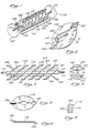
- a -cylinder type lawn grass and field mowing machine of the type which comprises an elongate bed knife 101 is shown in Figure 1 in phantom lines.
- One or more driving wheels 102 and 103 are also shown in Figure 1 in phantom.
- the driving wheels may be the support wheels for the mower or may be driven by some power or other means.
- the cylinder comprises a shaft 110 which has a square sectioned portion 112, the general configuration of which is best shown in Figure 4.
- a round portion 110 is used in the conventional way as a journal support and for attachment to whatever driving means it utilized.
- the cylinder also has a plurality of generally elliptical discs 114 to 122.
- the cylinder typically includes some partial ellipses, i.e., discs which are only partially in the form of an ellipse, being truncated so as to form the ends of the cylinder.
- Two end pieces 124 and 126 lie generally parallel to the other elliptical discs 114 to 122 while two short partial elliptical sections 128 and 130 are formed simply to square off the ends of the cylinder formed by the discs. These latter disc segments extend generally perpendicularly to the plane of the disc elements or disc segments, but otherwise work in the same manner.
- the cylinder also comprises a pair of support and fan rods 132 and 135 which extend from proximate to the shaft outwardly along the major axes of the elliptical discs.
- Figure 2 depicts a single elliptical disc mounted on the shaft with the support and fan elements.
- Disc 118 out the plurality of discs on the shaft is selected as exemplary to be depicted in Figure 2, and in Figures 5 and 6.
- the rectangular aperture which is in the centre of the disc 118, the major axis of the rectangle corresponding to the major axis of the disc is fitted over the square shaft 112.
- the plane of the disc resides at an acute angle relative to the axis of the shaft. This angle is about 40 degrees. Variation is permitted and any angle between about 30 degrees and between about 50 degrees can be used. Forty degrees appears to be about optimum, however.
- Ears extend, as best shown in Figure 6, in opposite directions relative to the plane of the disc, and, as best shown in Figure 5, at the respective ends of the major axis of the disc.
- these ears are identified as ears 136 and 138.
- These ears formed at the periphery of the disc at the ends of the major axis of the elliptical disc provide an acute angle and rapid relative- ment movement between the disc periphery and the bed knife as the disc rotates such that the major axis is approaching the bed knife.
- Figure 7 depicts the disc 118, in partial cross- section.
- the disc 118 has a relatively soft centre core portion 140 with hardened surfaces 142 and 144.
- the discs themselves may be formed of relatively soft steel, although somewhat hardened steel is generally preferred. It is extremely important, however, for maximum efficiency and minimum energy usage plus the savings of cost to resharpening, that the surfaces of the discs, 142, and 144, be case hardened, otherwise surface harened, relative to the central core portion 140 of the disc.
- the depth of hardening is typically from about 0.13 mm (0.005 inch) to about 0.63 mm (0.025 inch).
- the device depicted in Figure 8 comprises a continuous elongate abrading belt 150 and means, such as the drums 152 and 154 for carrying or revolving the continuous belt in a revolutionary path and presenting one portion 176 of the lateral surface of the continuous abrading belt at a straight line on the drum 154.
- a resilient surface 156 which may be a thin layer of rubber or other resilient material, on the drum 154.
- This layer will be from about 1.6 mm (one-sixteenth inch) to about 12.7 mm (one-half inch), generally.
- Any kind of desired drive means such as the motor 158 and the pulley and belt combination indicated generally at 160 may be used to drive the rollers and cause the abrading belt to revolve in a continuous path presenting a straight line backed by a resilient flat configuration.
- the drum 152 may be supported in any desired manner. It is desirable to provide some kind of support means, such as the journalled bracket 162 which is movably mounted on the base 164 by bolts 166 which may be loosened or tightened.
- the bracket 162 may be moved forwardly and backwardly by means of an adjusting bolt 168 which is threadedly received through a threaded aperture in bracket 170.
- This combination provides means for adjusting the relative tension of the sides of the continuous belt to assure that the belt travels in a continuous path and does not rise from side-to- side in its revolution.
- any convenient means may be provided for rotationally mounting the drum 154.
- a combination bracket and platform 172 which has a journalled upward bracket portion 174 on one end and a comparable structure on the other end for receiving the shaft portions of the drum 154 is provided.
- This bracket arrangement fixes the position of drum 154 and defines a straight line configuration for the belt with the resilient backing 156, the straight line surface being indicated generally at 176.
- a movable mount for supporting the cylinder is also provided.
- Figure 8 depicts such a bracket as comprising a base 180 with upstanding journal bracket elements 182 and 184 and a drive means 186 for rotatably driving the cylinder once it is mounted on the brackets.
- the brackets provide journals or other devices for supporting the cylinder for rotation.
- Rotation is provided by the motor 186.
- Springs, one of which is shown at 188, or other devices for permitting the controlled adjustment of the bracket 180 forwardly and backwardly, relative to the straight line surface 176 presented by the abrading belt, are provided along with means for moving the bracket back and forth.
- the means for moving comprises a pair of screws threadedly received in apertures in brackets 190 and 192 which are, in simplified form, shown on the plate 164.
- the wheel 196 By turning the wheel 196, in this simplified depiction, the bracket 180 is adjustably moved toward and away from the straight line surface 176 provided by the belt with the resilient backing 156.
- the belt is caused to revolve in a continuous path to present a rearwardly resiliently cushioned straight line surface, the periphery of the elliptical discs, which are in a cylindrical configuration overall, are presented against this straight line surface 176, resiliently backed surface and, preferably, the cylinder is rotated, generally in a direction such that the relative peripheral movement of the discs and the surface of the abrading belt are maximized.
- This rotational relationship between the notional cylindrical surface on the mower cylinder and the straight line surface 176 presented by the abrading belt sharpens, with great precision and accuracy, the discs which form the cutting cylinder.
Landscapes
- Engineering & Computer Science (AREA)
- Mechanical Engineering (AREA)
- Life Sciences & Earth Sciences (AREA)
- Environmental Sciences (AREA)
- Harvester Elements (AREA)
- Finish Polishing, Edge Sharpening, And Grinding By Specific Grinding Devices (AREA)
Claims (3)
Priority Applications (1)
| Application Number | Priority Date | Filing Date | Title |
|---|---|---|---|
| AT81901105T ATE11749T1 (de) | 1980-04-14 | 1981-04-13 | Verfahren und vorrichtung zum schleifen einer verbesserten scheibenrolle fuer einen maeher. |
Applications Claiming Priority (2)
| Application Number | Priority Date | Filing Date | Title |
|---|---|---|---|
| US06/140,254 US4267690A (en) | 1980-04-14 | 1980-04-14 | Disc reel mower and method and means of manufacturing the same |
| US140254 | 1987-12-31 |
Publications (3)
| Publication Number | Publication Date |
|---|---|
| EP0050137A1 EP0050137A1 (de) | 1982-04-28 |
| EP0050137A4 EP0050137A4 (de) | 1982-08-05 |
| EP0050137B1 true EP0050137B1 (de) | 1985-02-13 |
Family
ID=22490418
Family Applications (2)
| Application Number | Title | Priority Date | Filing Date |
|---|---|---|---|
| EP81901237A Expired EP0050151B1 (de) | 1980-04-14 | 1981-04-13 | Mähmaschine |
| EP81901105A Expired EP0050137B1 (de) | 1980-04-14 | 1981-04-13 | Verfahren und vorrichtung zum schleifen einer verbesserten scheibenrolle für einen mäher |
Family Applications Before (1)
| Application Number | Title | Priority Date | Filing Date |
|---|---|---|---|
| EP81901237A Expired EP0050151B1 (de) | 1980-04-14 | 1981-04-13 | Mähmaschine |
Country Status (4)
| Country | Link |
|---|---|
| US (1) | US4267690A (de) |
| EP (2) | EP0050151B1 (de) |
| JP (2) | JPS57501410A (de) |
| WO (2) | WO1981002967A1 (de) |
Families Citing this family (8)
| Publication number | Priority date | Publication date | Assignee | Title |
|---|---|---|---|---|
| US4719743A (en) * | 1981-11-16 | 1988-01-19 | Bokon William S | Nonhazardous mower |
| WO1984000465A1 (en) * | 1982-07-28 | 1984-02-16 | George Malcolm Byrd | Improvements relating to rotary agitators |
| DE3337177A1 (de) * | 1982-10-18 | 1984-04-19 | Hesston Corp., 67062 Hesston, Kan. | Motorgetriebene scherbalken-einstellvorrichtung fuer eine erntemaschine |
| EP0238827A1 (de) * | 1986-02-17 | 1987-09-30 | Klöckner-Humboldt-Deutz Aktiengesellschaft | Mähvorrichtung |
| GB9021040D0 (en) * | 1990-09-27 | 1990-11-07 | Qualcast Garden Prod | Cylinder lawnmowers |
| DE29703498U1 (de) * | 1997-02-27 | 1997-10-09 | Gerhard Dücker KG Landmaschinenfabrik, 48703 Stadtlohn | Mähgerät |
| DE10234814A1 (de) * | 2002-07-31 | 2004-02-19 | Walter Kolb | Schneidvorrichtung für Pflanzen |
| EP1795063A1 (de) * | 2005-12-01 | 2007-06-13 | Claudio Bighinati | Eine drehende Welle mit viereckigem Querschnitt, in der Quadrate montiert werden, die Messer zum Schneiden von Büschen und Landentwaldung halten |
Citations (2)
| Publication number | Priority date | Publication date | Assignee | Title |
|---|---|---|---|---|
| US2763101A (en) * | 1956-02-10 | 1956-09-18 | Philip T Johnson | Portable lawn mower grinder assembly |
| FR2246219A1 (de) * | 1973-10-05 | 1975-05-02 | Sperry Rand Corp |
Family Cites Families (10)
| Publication number | Priority date | Publication date | Assignee | Title |
|---|---|---|---|---|
| US2376847A (en) * | 1942-11-18 | 1945-05-22 | Int Silver Co | Apparatus for grinding and buffing metallic articles and the like |
| US2640309A (en) * | 1949-08-19 | 1953-06-02 | Merle K Benson | Cutter mechanism for mowing machines |
| US2772533A (en) * | 1955-01-17 | 1956-12-04 | Jr Harry B Shibley | Mower having ledger plate with cooperating wobble plate cutter |
| US2790293A (en) * | 1956-03-30 | 1957-04-30 | John V Crotty | Rotary cutting mechanism including cooperating toothed stationary cutter bar |
| US3054247A (en) * | 1958-12-01 | 1962-09-18 | Daniel P Roesler | Lawn mower |
| US3020682A (en) * | 1960-10-21 | 1962-02-13 | Gen Time Corp | Poishing machine for balance wheels |
| DE1577529A1 (de) * | 1966-09-26 | 1970-07-23 | Stehle Werkzeug & Maschf | Vorrichtung zum Schleifen von umlaufenden Werkzeugen fuer die Holzbearbeitung,insbesondere Keilzinkenfraeser |
| US3514934A (en) * | 1967-04-10 | 1970-06-02 | Samuel G Cassady | Cutting assembly |
| US3668814A (en) * | 1970-03-30 | 1972-06-13 | Minnesota Mining & Mfg | Surface grinding device |
| FR2264473A2 (en) * | 1974-03-19 | 1975-10-17 | Rousseau Joseph | Flail mower for mowing, ground clearance etc. - has circular flail support plates with double diametral folds |
-
1980
- 1980-04-14 US US06/140,254 patent/US4267690A/en not_active Expired - Lifetime
-
1981
- 1981-04-13 WO PCT/US1981/000477 patent/WO1981002967A1/en not_active Ceased
- 1981-04-13 JP JP56501716A patent/JPS57501410A/ja active Pending
- 1981-04-13 EP EP81901237A patent/EP0050151B1/de not_active Expired
- 1981-04-13 JP JP56501453A patent/JPS57501224A/ja active Pending
- 1981-04-13 EP EP81901105A patent/EP0050137B1/de not_active Expired
- 1981-04-13 WO PCT/US1981/000476 patent/WO1981002863A1/en not_active Ceased
Patent Citations (2)
| Publication number | Priority date | Publication date | Assignee | Title |
|---|---|---|---|---|
| US2763101A (en) * | 1956-02-10 | 1956-09-18 | Philip T Johnson | Portable lawn mower grinder assembly |
| FR2246219A1 (de) * | 1973-10-05 | 1975-05-02 | Sperry Rand Corp |
Also Published As
| Publication number | Publication date |
|---|---|
| WO1981002967A1 (en) | 1981-10-29 |
| EP0050137A1 (de) | 1982-04-28 |
| EP0050151B1 (de) | 1984-11-28 |
| JPS57501410A (de) | 1982-08-12 |
| US4267690A (en) | 1981-05-19 |
| WO1981002863A1 (en) | 1981-10-15 |
| EP0050137A4 (de) | 1982-08-05 |
| EP0050151A1 (de) | 1982-04-28 |
| EP0050151A4 (de) | 1982-07-19 |
| JPS57501224A (de) | 1982-07-15 |
Similar Documents
| Publication | Publication Date | Title |
|---|---|---|
| US5291724A (en) | Reel assembly for mower | |
| EP0050137B1 (de) | Verfahren und vorrichtung zum schleifen einer verbesserten scheibenrolle für einen mäher | |
| US4592108A (en) | Tool and method for scarifying a surface | |
| US4382397A (en) | Shear wheel for cutting fabric | |
| US3073100A (en) | Mower having helical cutter blade | |
| US2772533A (en) | Mower having ledger plate with cooperating wobble plate cutter | |
| US4267686A (en) | Lawn mower having flexible filament cutter elements | |
| US4005554A (en) | Blade sharpening device for rotatable chopping cylinders | |
| US6758730B1 (en) | Grinding machine and method of grinding grass mower rotary blades | |
| US2767543A (en) | Rotating cutting disc type mower | |
| US3863403A (en) | Blade sharpening device for rotatable chopping cylinders including hydraulic drive means | |
| CS211386B2 (en) | Segment of the leaf of tearing rotation head of the tyre tearing machine | |
| US4335543A (en) | Method and means of manufacturing an improved disc reel mower | |
| US3979887A (en) | Spiral lawn mowers | |
| US5791737A (en) | Elliptical disc grinder | |
| US4653255A (en) | Line reel mower | |
| CN219182107U (zh) | 一种剪切结构 | |
| WO1998036129A9 (en) | Elliptical disc grinder | |
| US2425106A (en) | Method of sharpening lawn mowers | |
| US4718198A (en) | Apparatus for grinding cutting edges of knives in tobacco cutting machines | |
| US20080196372A1 (en) | Cutting Unit with Moveable Groomer | |
| EP0997066B1 (de) | Apparat zum Schärfen von Schneidemesser | |
| KR960002900B1 (ko) | 짚대 절단장치 | |
| US2600892A (en) | Lawn mower having opposite handed helical cutting blades | |
| US3660971A (en) | Mower blade sharpening means |
Legal Events
| Date | Code | Title | Description |
|---|---|---|---|
| PUAI | Public reference made under article 153(3) epc to a published international application that has entered the european phase |
Free format text: ORIGINAL CODE: 0009012 |
|
| AK | Designated contracting states |
Designated state(s): AT CH DE FR GB LU NL SE |
|
| 17P | Request for examination filed |
Effective date: 19820413 |
|
| GRAA | (expected) grant |
Free format text: ORIGINAL CODE: 0009210 |
|
| AK | Designated contracting states |
Designated state(s): AT CH DE FR GB LI LU NL SE |
|
| PG25 | Lapsed in a contracting state [announced via postgrant information from national office to epo] |
Ref country code: AT Effective date: 19850213 |
|
| REF | Corresponds to: |
Ref document number: 11749 Country of ref document: AT Date of ref document: 19850215 Kind code of ref document: T |
|
| REF | Corresponds to: |
Ref document number: 3168859 Country of ref document: DE Date of ref document: 19850328 |
|
| ET | Fr: translation filed | ||
| PG25 | Lapsed in a contracting state [announced via postgrant information from national office to epo] |
Ref country code: LU Free format text: LAPSE BECAUSE OF NON-PAYMENT OF DUE FEES Effective date: 19850430 |
|
| PLBE | No opposition filed within time limit |
Free format text: ORIGINAL CODE: 0009261 |
|
| STAA | Information on the status of an ep patent application or granted ep patent |
Free format text: STATUS: NO OPPOSITION FILED WITHIN TIME LIMIT |
|
| 26N | No opposition filed | ||
| PGFP | Annual fee paid to national office [announced via postgrant information from national office to epo] |
Ref country code: NL Payment date: 19860430 Year of fee payment: 6 |
|
| PG25 | Lapsed in a contracting state [announced via postgrant information from national office to epo] |
Ref country code: LI Effective date: 19870430 Ref country code: CH Effective date: 19870430 |
|
| PG25 | Lapsed in a contracting state [announced via postgrant information from national office to epo] |
Ref country code: NL Effective date: 19871101 |
|
| NLV4 | Nl: lapsed or anulled due to non-payment of the annual fee | ||
| REG | Reference to a national code |
Ref country code: CH Ref legal event code: PL |
|
| PG25 | Lapsed in a contracting state [announced via postgrant information from national office to epo] |
Ref country code: GB Effective date: 19890413 |
|
| PG25 | Lapsed in a contracting state [announced via postgrant information from national office to epo] |
Ref country code: SE Effective date: 19890414 |
|
| GBPC | Gb: european patent ceased through non-payment of renewal fee | ||
| PG25 | Lapsed in a contracting state [announced via postgrant information from national office to epo] |
Ref country code: FR Free format text: LAPSE BECAUSE OF NON-PAYMENT OF DUE FEES Effective date: 19891228 |
|
| PG25 | Lapsed in a contracting state [announced via postgrant information from national office to epo] |
Ref country code: DE Effective date: 19900103 |
|
| REG | Reference to a national code |
Ref country code: FR Ref legal event code: ST |
|
| EUG | Se: european patent has lapsed |
Ref document number: 81901105.7 Effective date: 19900412 |