EP0050163A1 - Verfahren zur Formung von Metallteilen mit Gewinde - Google Patents
Verfahren zur Formung von Metallteilen mit Gewinde Download PDFInfo
- Publication number
- EP0050163A1 EP0050163A1 EP80106343A EP80106343A EP0050163A1 EP 0050163 A1 EP0050163 A1 EP 0050163A1 EP 80106343 A EP80106343 A EP 80106343A EP 80106343 A EP80106343 A EP 80106343A EP 0050163 A1 EP0050163 A1 EP 0050163A1
- Authority
- EP
- European Patent Office
- Prior art keywords
- workpiece
- grooves
- engaged
- edges
- edge
- Prior art date
- Legal status (The legal status is an assumption and is not a legal conclusion. Google has not performed a legal analysis and makes no representation as to the accuracy of the status listed.)
- Withdrawn
Links
- 238000000034 method Methods 0.000 title claims description 12
- 239000002184 metal Substances 0.000 title abstract description 10
- 238000005452 bending Methods 0.000 claims description 8
- 230000000295 complement effect Effects 0.000 claims description 5
- 238000004519 manufacturing process Methods 0.000 abstract description 10
- 239000000463 material Substances 0.000 abstract description 10
- 238000003754 machining Methods 0.000 abstract description 3
- 230000015572 biosynthetic process Effects 0.000 description 4
- 230000006835 compression Effects 0.000 description 3
- 238000007906 compression Methods 0.000 description 3
- 230000000750 progressive effect Effects 0.000 description 3
- 230000013011 mating Effects 0.000 description 2
- 238000013459 approach Methods 0.000 description 1
- 230000000994 depressogenic effect Effects 0.000 description 1
- 210000003141 lower extremity Anatomy 0.000 description 1
- 230000035515 penetration Effects 0.000 description 1
- 238000007493 shaping process Methods 0.000 description 1
- 210000001364 upper extremity Anatomy 0.000 description 1
- 238000003466 welding Methods 0.000 description 1
Images



Classifications
-
- B—PERFORMING OPERATIONS; TRANSPORTING
- B21—MECHANICAL METAL-WORKING WITHOUT ESSENTIALLY REMOVING MATERIAL; PUNCHING METAL
- B21D—WORKING OR PROCESSING OF SHEET METAL OR METAL TUBES, RODS OR PROFILES WITHOUT ESSENTIALLY REMOVING MATERIAL; PUNCHING METAL
- B21D37/00—Tools as parts of machines covered by this subclass
- B21D37/08—Dies with different parts for several steps in a process
-
- B—PERFORMING OPERATIONS; TRANSPORTING
- B21—MECHANICAL METAL-WORKING WITHOUT ESSENTIALLY REMOVING MATERIAL; PUNCHING METAL
- B21D—WORKING OR PROCESSING OF SHEET METAL OR METAL TUBES, RODS OR PROFILES WITHOUT ESSENTIALLY REMOVING MATERIAL; PUNCHING METAL
- B21D35/00—Combined processes according to or processes combined with methods covered by groups B21D1/00 - B21D31/00
Definitions
- the present invention provides an arrangement by which, threaded parts may be obtained from sheet metal entirely through a stamping operation.
- the result is a drastic reduction in the cost of producing the parts, much faster production, savings of material while obtaining parts of superior performance and better appearance.
- the part 10 is a bracket or hanger produced in accordance with the present invention, adapted to support a cable, tube, pipe, or the like. It includes an internally threaded cylindrical sleeve portion 11 from one end of which project two support members 14 and 15, which are side-by-side and generally U-shaped in side elevation and slightly divergent toward their outer ends. A tab 16 extends from the same end of the sleeve 11.
- the sleeve 11, support members 14 and 15, and tab 16 are integral, being made from a single piece of sheet metal. The connection to a cable received in the members 14 and 15 is completed by bending the outer ends of the members 14 and 15 around the cable and deflecting the tab 16 downwardly over the top of the cable.
- the hangers 10 are produced from sheet metal strip stock fed from a coil through a progressive die arrangement actuated by a reciprocating press. There are multiple stages in producing the completed parts 10, there being fourteen stages in the example described below. The number of stages necessary will depend upon the size and shape of the part, as well as the material from which it is made, and may be more or less than the fourteen stages described. At each stage part of the forming takes places so that as the strip of material is advanced the parts 10 are produced in increments.
- the punch includes a number of individual punch elements which move simultaneously in parallel paths as the press makes its downward stroke, cooperating with dies below to accomplish the various forming stages.
- All of the contouring of the workpiece, including the creation of a cylindrical threaded section, is accomplished by moving the punch rectilinearly toward and away from the die. No mandrel or other internal tool is used even though an accurately formed threaded section is produced.
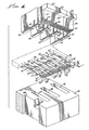
- Figure 1 illustrates. the strip of material 18 as it is formed in the various stages in producing the parts 10.
- the progressive die technique means that with each stroke of the press a completed part is obtained.
- the result is extremely rapid production at a fraction of - the cost of conventional manufacturing operations.
- the parts are of superior quality and offer advantages not realized with ordinary manufacturing procedures.
- a longitudinal groove 19 is formed in the upper surface of the strip material 18 adjacent its longitudinal edge 20.
- the punch has a flattened bottom edge, which causes the groove 19 to have a fiat bottom wall with two side walls diverging from it.
- the outer portion of the strip 18, beyond the groove 19, is cut off and a transverse slot 21 is formed.
- the outer part of the workpiece 18 is sheared off at the center of the groove 19, leaving an outer edge 22 on the workpiece with a bevel 23 at its upper portion.
- the bevel 23 provides an entrance to the threads in the sleeve portion 11 of the completed part 10, as well as causing the threads to be recessed a short distance inwardly of the sleeve end for their protection.
- Providing the groove 19 with a flat bottom wall avoids the creation of a.sharp edge when the outer part is cut off.
- a third forming stage additional cuts are made in the workpiece, producing and shaping various openings.
- This includes an opening 24, communicating with and inwardly of the slot 21 and an elongated rectangular opening 25.
- Adjacent to the opening 25 and parallel to it is an additional and thinner opening 26, which is rectangular except that at the end adjacent the opening 24 there is a narrow prong 27 which projects into the opening 26 along its longitudinal axis.
- Grooves are formed in the upper surface of the workpiece 18 along its edge portion inwardly of the bevel 23, in the next three forming stages, which result in screw threads when the sleeve portion 11 of the hanger 10 is formed subsequently. Accordingly, the grooves are at a shallow angle to the edge 22 of the workpiece so as to interconnect and produce a helix when this portion of the workpiece is given a cylindrical shape. Also, they are spaced apart the distance of the pitch of the threads.
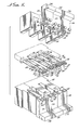
- Punches 29, 30, and 31 progressively form the threads in the fourth, fifth, and sixth stages, respectively, as seen in Figure 4.
- the rectangular outer part 32 of the workpiece 18, beyond the openings 24, is supported on a flat die surface 33 during these stages.
- pilots which accurately position the workpiece and restrain it during the fourth, fifth, and sixth forming stages.
- pilots 34 and 35 which have beveled lower corners, enter the openings 24 and 25 in the workpiece, straddling the strip 36 of the workpiece between these two openings. This positions the flat vertical surface 35 of the pilot 34 next to the edge 37 of the workpiece opening 24 on one side of the workpiece section 32 at the fourth stage.
- a rectangular die opening 38 receives the lower portions of the pilots 34 and 35 upon the downward stroke of the press.
- a pilot 39 enters the opening 24 of the workpiece to position its flat vertical surface 40 alongside the edge 37 of the workpiece.
- the pilot 39 is the same as the pilot 34. Its surface 40 also is next to the edge 37 on one side of the workpiece section 32 of the fifth stage when the press is in its downward stroke. Additional pilots 41 and 42 are the same as the pilots 34 and 39, fitting next to the edges 37 during the fifth and sixth stages.
- pilots 43, 44, and 45 Inwardly of the pilots 39, 41, and 42 are pilots 43, 44, and 45, respectively, which are the same as the pilot 35 and adapted to enter the workpiece openings 25 during the fourth, fifth, and sixth stages.
- Die opening 46 receives the pilots 39 and 43
- die opening 47 receives the pilots 41 and 44
- die opening 48 is for pilots 42 and 45.
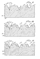
- the first thread formation step at stage four is shown in enlarged sectional views, Figures 6 and 9.
- the punch 29 strikes the outer part 32 of the workpiece at stage four, portions of the workpiece become compressed.
- the punch surfaces 35 and 40 being adjacent the workpiece edges 34, restrain the outer part 32 of the workpiece from movement inwardly from the compression. Outward expansion of the workpiece can take place, however, as the outer workpiece edge 22 is unconstrained.
- Parallel ridges 50 on the undersurface of the punch 29 form complementary grooves 51 in the outer part 32 of workpiece 18.
- straight sloping walls 52 are formed at an angle of 30° relative to a line perpendicular to the upper surface of the workpiece, i.e., to the direction of movement of the punch.
- the opposite walls 53, on the side where the workpiece is unconstrained, are more steeply sloped at an angle of 17° to the vertical.
- Bottom walls 54 interconnect the outwardly diverging sidewalls 52 and 53.
- the projections of the sidewalls 52 and 53 intersect at lines 55 below the bottom walls 54 of the grooves, as shown in Figure 9. These intersections of the groove walls are spaced apart a distance equal to the pitch of the thread to be produced.
- the ridges 56 on the punch 30 have locations corresponding to the ridges 50 of the punch 29.
- the ridges 59 on the punch 31 deepen the grooves 51 and widen them by imparting a 30° angle to the outer walls 53 of the grooves.
- the inner groove walls 52 continue to have a 30° slope.
- the bottom walls 54 of the grooves are sunk substantially to the full depth of the thread, although a minor amount of thread deepening occurs during some of the bending stages, as explained below.
- the bottom walls 54 are made more narrow than at the fifth stage, notwithstanding the fact that the total groove width is increased.
- the intersecting lines 55 of the sidewall projections remain spaced apart the distance of the pitch of the threads to be produced.
- the sidewalls and bottom walls of the grooves 51 define a desired thread configuration, such as that of a conventional screw thread.
- the roots of the threads are provided by the bottom walls 54 of the grooves and the upper surface portions 57 beetween the grooves 51 act as the crests of the threads.
- the inner edge 37 of the outer part 32 of the workpiece is restrained by the pilots 41 and 42 so that increased lateral dimension can occur only in the outward direction.
- the ridges 59 on the punch 31 correspond in locations to the ridges 50 and 56 of the punches 29 and 30, so that the grooves 51 do not shift positions at the sixth stage.
- the progressive thread formation at the fourth, fifth, and sixth stages, deepening the grooves and changing the flank angles, is important in achieving accurate thread contouring. Also, when the completed part has an operative element beyond the threaded section, such as the U-shaped supports'14 and 15, there should be restraint against lateral expansion of the threaded section on the side of such an element, with expansion being allowed in the other direction, so that the material of the workpiece will flow properly during the formation of the grooves to enable the grooves to be given the desired shape while avoiding die breakage.
- the outer portion of the prong 27 is bent downwardly at an angle of 90°.
- the seventh stage ( Figure 5) is the first in contouring the outer part 32 of the workpiece, ultimately to give it the cylindrical configuration necessary to form the sleeve portion 11 of the completed part 10.
- the die 60 at the seventh stage, has an upper surface with a convex portion 61 at the center and concave parts 62 and 63 at the outer edges. These curved die surfaces are segments of cylinders with their axes perpendicular to the longitudinal workpiece edge 22.
- the punch in this instance is defined by two horizontal threaded studs 64 and 65, which are threaded into openings in a vertical flange 66. This positions the studs 64 and 65 above the concave die surfaces 62 and 63, respectively.
- the threads of the studs 64 and 65 are of a pitch and configuration to match the grooves 51 in the workpiece, with which they are aligned. Consequently, when the outer part 32 of the workpiece is struck by the studs 64 and 65, it is deflected over the convex die surface 61 and into the concave edge portions 62 and 63, but the shape of the grooves 51 remains unchanged.
- This forming step gives the workpiece a convex central portion 67 and concave upwardly curled edge portions 68 and 69.
- the central portion of the workpiece remains convex upwardly and the outer portions are given a greater upward concave curl.
- the die 71 at the eighth stage, has an upper surface which has a narrower convex central portion 72, and outer concave portions 73 and 74, which are closer to the center of the die than are the concave edge portions of the die 60. Studs 75 and 76, held on a support flange 77, act as the punch and are similar to the studs 64 and 65. However, the studs 75 and 76 are closer together to correspond to the positions of the surfaces 73 and 74 of the die 71.
- the die 79 has a relatively narrow central convex portion 80 and deeper side edge concave portions'81 and 82.
- the portions 81 and 82 are closer to the center of the die 79 than are the portions 73 and 74 with respect to the center of the die 71.
- the outer side portions of the studs 83 and 84 are cut away to provide flat surfaces 86 and 86 to give the studs 83 and 84 clearance for removal on the upward stroke.
- the thread grooves are continued for a distance into the flat surfaces 86 and 87, so that damage to the threads of the workpiece will not occur as it is caused to bend upwardly around the studs 83 and 84.
- the outer part 32 of the workpiece therefore, at the conclusion of the ninth forming stage, has edge portions 68 and 69 which curl inwardly and overlap part of the bottom portion of the outer part 32 of the workpiece.
- the strip 36 is cut off, leaving the outer part 32 of the workpiece connected to elongated strips 88 and 89, located one on either side of the prong 27.
- the tenth die stage further wraps the end portion of the workpiece around toward its cylindrical configuration.
- the die 91 at the tenth stage has a concave surface 92 which approaches a semicylindrical shape. However, it is flattened at its intermediate side portions 93 and 94.
- Above the die surface 92 is a punch 95 in the form of a stud carried by a vertical flange 96, again having threads which match those of the end portion of the workpiece.
- the sides 97 and 98 of the stud 95 are flattened to permit the stud to leave the workpiece on the upward stroke.
- the punch 95 When the punch 95 hits the workpiece it drives the end part 32 into the die opening 92, causing it to assume the shape of the die opening.
- the flattened intermediate side portions 93 and 94 give the die opening a taper that helps center the end part 32 of the workpiece in the die opening.
- the single stud 95 engages the central part 67 of the workpiece and cooperates with the die opening to reverse the curvature in this area from convex to concave.
- the opposite edges 99 and 100 of the end part 32 of the workpiece remain spaced apart, but have been moved closer together because of the increased curvature given the workpiece, so that there is a narrow gap between them.
- outer part 32 of the workpiece is formed into a sleeve, which approximates but does not achieve the cylindrical configuration of the sleeve portion 11 of the completed part.
- the die 102 at the eleventh stage has a concave surface 103 with rounded convex corners.
- the punch 104 is similar, having a recess 105 of the same shape. At the eleventh stage, therefore, the opposite edges 99 and 100 of the outer part 32 of the workpiece, which are at the central portion of the punch cavity 105, are brought together to produce a sleeve.
- the end part 32 has approached a cylindrical configuration sufficiently prior to the eleventh stage to enable the die surfaces 103 and 105 to push inwardly on the workpiece toward its axis as the workpiece is forced into the die openings.
- the engagement with the outer part 32 of the workpiece is only on its exterior, i.e., the side opposite the thread grooves 51, with no mandrel entering the sleeve.
- the surfaces 103 and 105 together define a closed curved shaped so as to give the workpiece a somewhat elliptical contour, with the major axis extending vertically.
- the width of the elliptical section i.e., the horizontal dimension normal to the direction of movement of the punch) is equal to or slightly less than the outside diameter of the sleeve 11 of the completed part 10.
- the die 106 at the twelfth forming stage includes a semicylindrical concave surface 107, having the same curvature as the sleeve portion 11 of the completed part 10, which intersects a flat upper die surface 108.
- the punch 109 of the twelfth stage has a semicylindrical surface 110 corresponding to the die surface 107, also being complementary to the sleeve portion 11 of the completed part 10.
- the edges of the surface 110 extend to a flat horizontal bottom surface 111 of the punch.
- the workpiece end portion 32 is compressed as it is formed in the twelfth stage. This compression causes the material to be forced outwardly to engage the surfaces 107 and 110 throughout its periphery, irrespective of the deviations from a cylindrical form present as it enters the twelfth stage. This compression is accomplished by making the end portion 32 longer between the edges 99 and 100 than the circumference required for the completed sleeve portion 11. As a result, the portion 32 is forced to comply with die surfaces of lesser circumference than it possesses.
- the grooves 51 in the outer portion 59 of the workpiece are at an angle relative to the axis of the completed sleeve such that a continuous helical thread is produced when the edges 99 and 100 are brought together. This means that the end of one groove 51 precisely aligns with the end of the next adjacent groove 51 at the opposite edge.
- the projecting strips 88 and 89 are bent'to provide half of the curvature of the U-shaped retainer portions 14 and 15 of the completed part 10.
- the outer portion 32 of the workpiece is held between the surface 112 of the die 113 and the surface 114 of the punch 115. This maintains the end portion 32 in a horizontal attitude, irrespective of the bending of the projecting strips 88 and 89.
- the workpiece receives its final forming and the completed part 10 is separated.
- the outer portion 32 of the'workpiece is held between the surfaces of a punch 116 and a die 117.
- the threads of the part 10 may be made self-locking so that they will provide tight engaement at any rotational position and will not be loosened by vibration or other service conditions. This is accomplished by making the thread grooves 51 more shallow at the inner end of the threaded section than at the outer end where the mating threaded part enters.
- the ridges on the punches 29, 30, and 31 are made less deep at the portions of these punches that strike the workpiece inwardly of the edge 32 than are the ridges adjacent the edge 22 to produce this relationship of the thread grooves.
- the entrance threads of full depth allow the mating of the threads to start without difficulty.
- the inner threads of less depth cause the sleeve portion 11 to grip the stud, exerting a compressive force on its exterior so that friction resists relative rotation.
- the stud, entering the tapered threads, can tend to spring the sleeve edges 99 and 100 very slightly apart to produce a resilient, but yielding, gripping force.
- the workpiece is allowed to expand in two directions as the grooves for the thread are formed. With the two opposite edges unrestrained, the workpiece will expand bidirectionally outwardly under the impacts of the punches.
- the flank or wall angles of the grooves are substantially the same in each stage, so each groove is substantially symmetrical in all stages.
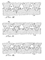
- the punch 120 of the first stage has a series of parallel ridges 121 which are spaced laterally apart a distance corresponding to the pitch of the thread to be produced.
- the flanks 122 and 123 of the ridges 121 converge downwardly as shown, and are steeper than that of the flanks in the desired finished thread.
- the flanks 122 and 123 may be at an angle of 23 u .
- the punch 126 has parallel ridges 127 which are spaced correspondingly to ridges 121 and are adapted to register with and be inserted into the grooves 225.
- the flanks or sidewalls 128 and 129 cf ridges 127 are less steeply inclined than are the flanks 122 and 123, but are still more steeply inclined than are the flanks of the desired completed thread.
- a 26 0 flank angle is suitable.
- the groove walls are given their final inclinations, for example 30°.
- the flanks 131 and 132 of the ridges 133 of the punch 134 are at a 30 0 angle.
- each ridge has a rounded contour.
- the rounded shape helps the ridges penetrate the workpiece so as to cause the metal of the workpiece to flow better during the different forming stages, whereas sharp corners have more tendency to dig into the workpiece metal.
Landscapes
- Engineering & Computer Science (AREA)
- Mechanical Engineering (AREA)
- Forging (AREA)
Priority Applications (1)
| Application Number | Priority Date | Filing Date | Title |
|---|---|---|---|
| EP80106343A EP0050163A1 (de) | 1980-10-17 | 1980-10-17 | Verfahren zur Formung von Metallteilen mit Gewinde |
Applications Claiming Priority (1)
| Application Number | Priority Date | Filing Date | Title |
|---|---|---|---|
| EP80106343A EP0050163A1 (de) | 1980-10-17 | 1980-10-17 | Verfahren zur Formung von Metallteilen mit Gewinde |
Publications (1)
| Publication Number | Publication Date |
|---|---|
| EP0050163A1 true EP0050163A1 (de) | 1982-04-28 |
Family
ID=8186847
Family Applications (1)
| Application Number | Title | Priority Date | Filing Date |
|---|---|---|---|
| EP80106343A Withdrawn EP0050163A1 (de) | 1980-10-17 | 1980-10-17 | Verfahren zur Formung von Metallteilen mit Gewinde |
Country Status (1)
| Country | Link |
|---|---|
| EP (1) | EP0050163A1 (de) |
Cited By (2)
| Publication number | Priority date | Publication date | Assignee | Title |
|---|---|---|---|---|
| WO2009094981A1 (de) * | 2008-02-02 | 2009-08-06 | Acument Gmbh & Co Ohg | Fügeverbindung für blechumformteile und durchzug mit einer solchen fügeverbindung |
| CN109201878A (zh) * | 2018-08-27 | 2019-01-15 | 沈阳聚和源汽车部件有限公司 | 一种空调压缩机地脚级进模具 |
Citations (8)
| Publication number | Priority date | Publication date | Assignee | Title |
|---|---|---|---|---|
| US1369975A (en) * | 1916-12-01 | 1921-03-01 | Edward E Johnson | Method of making couplings |
| US1433878A (en) * | 1920-10-18 | 1922-10-31 | Nat Acme Co | Feed collet and method of making the same |
| US1502133A (en) * | 1921-10-05 | 1924-07-22 | Bolling Mfg Company | Process of forming turnbuckles |
| AT164592B (de) * | 1946-04-04 | 1949-11-25 | Securit S E D L C Soc | Verfahren zur Herstellung von im wesentlichen hülsenförmigen Bauteilen mit Innengewinde und längsgeschlitztem Mantel |
| US2881510A (en) * | 1954-07-08 | 1959-04-14 | Charles O Larson | Turnbuckle and method of forming the same |
| DE1117855B (de) * | 1956-02-06 | 1961-11-23 | Vermont American Corp | Bohrer und Verfahren zu seiner Herstellung |
| US3443542A (en) * | 1964-02-12 | 1969-05-13 | Heyman Mfg Co | Method of forming wide crimp blade |
| GB1470791A (en) * | 1974-11-11 | 1977-04-21 | Super Electrical Products Ltd | Suspension hook |
-
1980
- 1980-10-17 EP EP80106343A patent/EP0050163A1/de not_active Withdrawn
Patent Citations (8)
| Publication number | Priority date | Publication date | Assignee | Title |
|---|---|---|---|---|
| US1369975A (en) * | 1916-12-01 | 1921-03-01 | Edward E Johnson | Method of making couplings |
| US1433878A (en) * | 1920-10-18 | 1922-10-31 | Nat Acme Co | Feed collet and method of making the same |
| US1502133A (en) * | 1921-10-05 | 1924-07-22 | Bolling Mfg Company | Process of forming turnbuckles |
| AT164592B (de) * | 1946-04-04 | 1949-11-25 | Securit S E D L C Soc | Verfahren zur Herstellung von im wesentlichen hülsenförmigen Bauteilen mit Innengewinde und längsgeschlitztem Mantel |
| US2881510A (en) * | 1954-07-08 | 1959-04-14 | Charles O Larson | Turnbuckle and method of forming the same |
| DE1117855B (de) * | 1956-02-06 | 1961-11-23 | Vermont American Corp | Bohrer und Verfahren zu seiner Herstellung |
| US3443542A (en) * | 1964-02-12 | 1969-05-13 | Heyman Mfg Co | Method of forming wide crimp blade |
| GB1470791A (en) * | 1974-11-11 | 1977-04-21 | Super Electrical Products Ltd | Suspension hook |
Cited By (2)
| Publication number | Priority date | Publication date | Assignee | Title |
|---|---|---|---|---|
| WO2009094981A1 (de) * | 2008-02-02 | 2009-08-06 | Acument Gmbh & Co Ohg | Fügeverbindung für blechumformteile und durchzug mit einer solchen fügeverbindung |
| CN109201878A (zh) * | 2018-08-27 | 2019-01-15 | 沈阳聚和源汽车部件有限公司 | 一种空调压缩机地脚级进模具 |
Similar Documents
| Publication | Publication Date | Title |
|---|---|---|
| US4266310A (en) | Arrangement for forming metal parts | |
| US4584753A (en) | Apparatus for connecting sheet metal pieces | |
| US4781501A (en) | Self-plugging blind fastener | |
| EP0307119A1 (de) | Befestigungsmittel mit Schraubgewinde | |
| US4233878A (en) | Barb and method of making same | |
| US5993320A (en) | Tee nut and method of manufacture | |
| US3451080A (en) | Screws | |
| WO2000043683A1 (en) | Improved self-tapping thread fastener and a blank therefor | |
| US3681963A (en) | Self-thread forming threaded fasteners and method and apparatus for making the same | |
| US4860570A (en) | Low tonnage high quality thread stamping | |
| US4724694A (en) | Method of manufacturing a thread-forming screw | |
| EP0538486B1 (de) | Nähmaschinenadel und Herstellungsverfahren | |
| US7097403B1 (en) | Reduced material fastener | |
| US1913143A (en) | Means for roll-threading and pointing screws | |
| US2169182A (en) | Fastener | |
| US3461708A (en) | Method of forming conduit clamps | |
| EP0050163A1 (de) | Verfahren zur Formung von Metallteilen mit Gewinde | |
| US4572875A (en) | Blank for a thread forming screw | |
| US3183531A (en) | Method of forming a screw with cutting edges | |
| IE63122B1 (en) | Self-drilling blind rivet and method for making same | |
| CA1138607A (en) | Method of forming screw threaded metal parts | |
| US4034586A (en) | Thread rolling die and method of thread rolling | |
| US3196654A (en) | Screw rolling die | |
| US3166769A (en) | Method and apparatus for heading a fastener | |
| US2074678A (en) | Means and method for making nuts |
Legal Events
| Date | Code | Title | Description |
|---|---|---|---|
| PUAI | Public reference made under article 153(3) epc to a published international application that has entered the european phase |
Free format text: ORIGINAL CODE: 0009012 |
|
| AK | Designated contracting states |
Designated state(s): DE FR GB SE |
|
| 17P | Request for examination filed |
Effective date: 19820928 |
|
| STAA | Information on the status of an ep patent application or granted ep patent |
Free format text: STATUS: THE APPLICATION IS DEEMED TO BE WITHDRAWN |
|
| 18D | Application deemed to be withdrawn |
Effective date: 19850503 |