EP0050165A1 - Lamellentüre aus Streifen aus flexiblem Kunststoffmaterial - Google Patents
Lamellentüre aus Streifen aus flexiblem Kunststoffmaterial Download PDFInfo
- Publication number
- EP0050165A1 EP0050165A1 EP80107971A EP80107971A EP0050165A1 EP 0050165 A1 EP0050165 A1 EP 0050165A1 EP 80107971 A EP80107971 A EP 80107971A EP 80107971 A EP80107971 A EP 80107971A EP 0050165 A1 EP0050165 A1 EP 0050165A1
- Authority
- EP
- European Patent Office
- Prior art keywords
- door according
- pivot
- slat door
- slat
- bearing groove
- Prior art date
- Legal status (The legal status is an assumption and is not a legal conclusion. Google has not performed a legal analysis and makes no representation as to the accuracy of the status listed.)
- Granted
Links
- 239000000463 material Substances 0.000 title claims description 3
- 229920003023 plastic Polymers 0.000 title description 6
- 239000004033 plastic Substances 0.000 title description 6
- 229920002457 flexible plastic Polymers 0.000 claims description 2
- 241000446313 Lamella Species 0.000 description 7
- 239000000725 suspension Substances 0.000 description 2
Images


Classifications
-
- E—FIXED CONSTRUCTIONS
- E06—DOORS, WINDOWS, SHUTTERS, OR ROLLER BLINDS IN GENERAL; LADDERS
- E06B—FIXED OR MOVABLE CLOSURES FOR OPENINGS IN BUILDINGS, VEHICLES, FENCES OR LIKE ENCLOSURES IN GENERAL, e.g. DOORS, WINDOWS, BLINDS, GATES
- E06B3/00—Window sashes, door leaves, or like elements for closing wall or like openings; Layout of fixed or moving closures, e.g. windows in wall or like openings; Features of rigidly-mounted outer frames relating to the mounting of wing frames
- E06B3/70—Door leaves
- E06B3/80—Door leaves flexible
Definitions
- the invention relates to a lamella door with a plurality of parallel, mutually overlapping strips of flexible plastic material which, in the idle state, hang vertically at one end on swivel holders which have a receiving slot for clamping the upper edge of the strips.
- the swivel holders there have two-part bearing sleeves, which are pivotably mounted on a bearing tube attached to the lintel.
- the two halves of the sleeve-like swivel holder are connected or detached from one another after being attached to the bearing tube, so that the bearing tube can be removed by dividing the swivel holder.
- This assembly and disassembly effort is considered to be expensive, particularly for tall and large doors.
- the invention is therefore based on the object of designing a louvre door so that the individual strips can be more easily assembled or disassembled without endangering the safety of the suspension.
- the object is achieved according to the invention with a louvre door of the type mentioned above in that the swivel holders have a bent end section which forms a hinge member which can be clipped into a bearing groove which is adapted to the arch shape and is fastened to the lintel at a distance.
- the profile of the hinge member z. B.
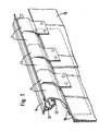
- FIG. 1 shows three plastic strips 10 arranged side by side with overlapping edges, which form the flexible slats of the slat door. These plastic strips 10 are provided on their upper narrow side with a number of swivel brackets 11 corresponding to their width, which are clipped into a bearing groove 12. One edge of the channel 12 is connected via a double-walled retaining web 13 to a mounting plate 14 which is fastened to a door lintel, not shown.
- the swivel holders 11 and 11 ' are flat bodies which are double-walled in their one end region 11a and 11a' and form a slot 15, 15 'there with toothed slot walls, in which the upper one Edge area 10a of the associated plastic strip 10 can be inserted. It is clamped in this slot 15, 15 'by means of clamping screws or rivets, not shown, which can be inserted into through openings 16 in the end region 11a of the swivel holder 11 while piercing the edge region 10a of the plastic strip 10.
- the cranked middle region 11b merges into a spirally bent end section 11c.
- This spirally bent end section 11c of the swivel holder 11 forms a hinge member which can be clipped into the bearing groove 12, the cross section of which resembles the spiral arch shape of the end section 11c of the swivel holder has an adapted profile.
- the hinge member 11c Due to the spiral shape, the hinge member 11c has a different diameter in each angular position.
- the spiral shape is now chosen so that only in the pivoting position of the swivel holder 11 shown in FIG. 3, which corresponds to the vertical position assumed by the plastic strips 10 in their rest position, the diameter of the spirally bent end section 11c is so small that it is separated by the inserted into the free edge 12a of the bearing trough 12 and the mounting plate 14 existing gap S and thus the swivel holder can be brought into the clip position shown in FIG. 3.
- the cranked middle region 11b' merges into an inwardly bent end section which is composed of two circular arc sections 11d and 11e which are joined at a jump point 17 forming a stop step by an uncurved one Section 11f are interconnected. Also in this form of the hinge member forming end portion of the pivot holder 11 'it is achieved that the end portion only in a certain pivot position, namely the deflection position shown in FIG. 6, by the stepped in shape between a mounting plate 14' and the end End section adapted bearing groove 12 'existing gap S' can be clipped into the bearing groove 12 '.
- FIG. 5 shows the swivel holder 11 'in its swivel end position opposite to the clip-in position, in which the straight web 11f of the end section 11d / e / f abuts against a stepped surface 18 of the bearing groove 12'.
- a bearing web not shown in the drawing, which, like in known lamella doors which are to be moved from the area of the door opening when required, carries rollers which are fastened in a lintel or in running track embedded in the lintel are stored.
Landscapes
- Engineering & Computer Science (AREA)
- Civil Engineering (AREA)
- Structural Engineering (AREA)
- Securing Of Glass Panes Or The Like (AREA)
- Hinges (AREA)
- Curtains And Furnishings For Windows Or Doors (AREA)
- Wing Frames And Configurations (AREA)
- Specific Sealing Or Ventilating Devices For Doors And Windows (AREA)
- Extensible Doors And Revolving Doors (AREA)
Abstract
Description
- Die Erfindung betrifft eine Lamellentüre mit mehreren parallelen, sich gegenseitig überlappenden Streifen aus flexiblem Kunststoffmaterial, die im Ruhezustand an einem Ende an Schwenkhaltern vertikal hängen, die einen Aufnahmeschlitz zum Einklemmen des oberen Randes der Streifen haben.
- Lamellentüren mit den vorstehend genannten Merkmalen sind bereits vorgeschlagen worden. Die Schwenkhalter weisen dort zweiteilige Lagerhülsen auf, die auf einem am Türsturz angebrachten Lagerrohr schwingbar gelagert sind. Zur Montage oder Demontage der Streifen der Lamellentüre werden die beiden Hälften der hülsenartigen Schwenkhalter nach dem Ansetzen am Lagerrohr miteinander verbunden bzw. voneinander gelöst, damit durch Aufteilen der Schwenkhalter die Abnahme vom Lagerrohr möglich wird. Dieser Montage- bzw. Demontageaufwand wird insbesondere bei hohen und großen Türen als aufwendig angesehen. Der Erfindung liegt daher die Aufgabe zugrunde, eine Lamellentüre so auszubilden, da3 die einzelnen Streifen leichter montiert oder demontiert werden können, ohne die Sicherheit der Aufhängung zu gefährden.
- Die gestellte Aufgabe wird mit einer Lamellentüre der eingangs genannten Art erfindungsgemäß dadurch gelöst, daß die Schwenkhalter einen eingebogenen Endabschnitt aufweisen, der ein Scharnierglied bildet, das in eine der Bogenform angepaßte, mit Abstand am Türsturz befestigte Lagerrinne einklipsbar ist. Dabei läßt sich das Profil des Scharniergliedes z. B. nach einer echten Spiralkurve oder nach einer aus zwei an einer Sprungstelle miteinander verbundenen Kreisbogenabschnitten unterschiedlicher Durchmesser zusammengesetzten Kurve formen, die ein Einklipsen des Scharniergliedes in die Lagerrinne, deren Profil eine entsprechende Bogenkrümmung aufweist, nur in einer bestimmten Scharnierstellung, beispielsweise der vertikalen Ruhestellung der Streifen der Lamellentüre, durch den zwischen dem freien Rand der Lagerrinne und dem Türsturz oder einer Montageplatte der Lagerrinne bestehenden Spalt hindurch erlaubt. In jeder anderen Schwenklage ist dieser Spalt aber schmäler als der spaltparallele Durchmesser des Bogenprofils des Scharniergliedes. Dadurch ist nur in einer bestimmten Schwenkstellung der Scharnierglieder ein Aushängen der Lamellenstreifen aus der Lagerrinne am Türsturz möglich, während in allen anderen Endstellungen die Scharnierglieder nicht ausgehängt werden können. Somit ist eine sichere Aufhängung der Streifen der Lamellentüre gewährleistet, und beim Öffnen der Lamellentüre und dem dabei auftretenden Verschwenken der Lamellen mit entsprechender Auslenkung der Scharnierglieder muß kein unerwünschtes Ausklipsen der Lamellen aus der Lagerrinne befürchtet werden.
- Nachfolgend wird ein Ausführungsbeispiel des Erfindungsgegenstandes anhand der beiliegenden Zeichnungen näher erläutert.
- Im einzelnen zeigen:
- Fig. 1 eine perspektivische Übersichtsdarstellung von einem Teil einer Lamellentüre;
- Fig. 2 eine erste Ausführungsform eines Schwenkhalters der Halteeinrichtung beim Einklipsen in eine Lagerrinne in gegenüber Fig. 1 vergrößertem Maßstab;
- Fig. 3 eine der Fig. 2 entsprechende Darstellung mit dem Schwenkhalter in eingeklipstem Zustand;
- Fig. 4 eine der Fig. 3 entsprechende Darstellung einer zweiten Ausführungsform eines Schwenkhalters;
- Fig. 5 der in Fig. 4 dargestellte Schwenkhalter in einer von der Einklipsstellung abweichenden Schwenkstellung;
- Fig. 6 der in Fig. 4 und 5 dargestellte Schwenkhalter in der Einklips-Schwenkstellung.
- Die Übersichtsdarstellung der Fig. 1 zeigt drei nebeneinander mit sich überlappenden Rändern angeordnete Kunststoffstreifen 10, welche die flexiblen Lamellen der Lamellentüre bilden. Diese Kunststoffstreifen 10 sind an ihrer oberen Schmalseite mit einer ihrer Breite entsprechenden Anzahl von Schwenkhaltern 11 versehen, die in eine Lagerrinne 12 eingeklipst sind. Der eine Rand der Lagerrinne 12 ist über einen doppelwandigen Haltesteg 13 mit einer Montageplatte 14 verbunden, die an einem nicht dargestellten Türsturz befestigt wird.
- Wie die vergrößerten Darstellungen der Fig. 2 - 6 zeigen, sind die Schwenkhalter 11 und 11' Flachkörper, die in ihrem einen Endbereich 11a bzw. 11a' doppelwandig sind und dort einen Schlitz 15, 15' mit gezahnten Schlitzwänden bilden, in welchen der obere Randbereich 10a des zugeordneten Kunststoffstreifens 10 einschiebbar ist. Er wird in diesem Schlitz 15, 15' mittels nicht dargestellter Spannschrauben oder Niete festgeklemmt, die in Durchgangsöffnungen 16 im Endbereich 11a der Schwenkhalter 11 unter Durchstoßung des Randbereiches 10a des Kunststoffstreifens 10 einsetzbar sind. An den mit dem Schlitz 15, 15' versehenen Endbereich 11a bzw. 11a' schließt sich ein abgekröpfter Mittelbereich 11b bzw. 11b' an.
- Bei dem in den Fig. 2 und 3 dargestellten ersten Ausführungsbeispiel eines Schwenkhalters 11 geht der abgekröpfte Mittelbereich 11b in einen spiralförmig eingebogenen Endabschnitt 11c über. Dieser spiralförmig eingebogene Endabschnitt 11c des Schwenkhalters 11 bildet ein Scharnierglied, das in die Lagerrinne 12 einklipsbar ist, deren Querschnitt ein an die Spiralbogenform des Endabschnittes 11c des Schwenkhalters angepaßtes Profil aufweist.
- Durch die Spiralform weist das Scharnierglied 11c in jeder Winkellage einen anderen Durchmesser auf. Die Spiralform ist nun so gewählt, daß nur in der aus Fig. 3 ersichtlichen Schwenkstellung des Schwenkhalters 11, die der von den Kunststoffstreifen 10 in ihrer Ruhestellung eingenommenen Vertikalstellung entspricht, der Durchmesser des spiralförmig gebogenen Endabschnittes 11c so klein ist, daß er durch den zwischen dem freien Rand 12a der Lagerrinne 12 und der Montageplatte 14 bestehenden Spalt S eingeschoben und somit der Schwenkhalter in die aus Fig. 3 ersichtliche Einklipsstellung gebracht werden kann.
- Bei der in den Fig. 4 - 6 dargestellten zweiten Ausführungsform eines Schwenkhalters 11' geht der abgekröpfte Mittelbereich 11b' in einen einwärts gebogenen Endabschnitt über, der aus zwei Kreisbogenabschnitten 11d und 11e zusammengesetzt ist, die an einer eine Anschlagstufung bildenden Sprungstelle 17 durch einen ungekrümmten Abschnitt 11f miteinander verbunden sind. Auch bei dieser Form des das Scharnierglied bildenden Endabschnittes des Schwenkhalters 11' wird erreicht, daß der Endabschnitt nur in einer bestimmten Schwenkstellung, nämlich der aus Fig. 6 dargestellten Auslenkstellung, durch den zwischen einer Montageplatte 14' und dem Ende der in ihrer Form dem gestuften Endabschnitt angepaßten Lagerrinne 12' bestehenden Spalt S' hindurch in die Lagerrinne 12' einklipsbar ist.
- Fig. 5 zeigt den Schwenkhalter 11' in seiner zur Einklipsstellung entgegengesetzten Schwenkendstellung, in welcher der geradlinige Steg 11f des Endabschnittes 11d/e/f gegen eine Stufungsfläche 18 der Lagerrinne 12' anschlägt.
- Anstelle der Montageplatte 14, 14' könnte als Befestigungsteil auch ein in der Zeichnung nicht dargestellter Lagersteg vorgesehen sein, der wie bei bekannten Lamellentüren, die bei Bedarf aus dem Bereich der Türöffnung verfahren werden sollen, Laufrollen trägt, die in einer am Türsturz befestigten oder in den Türsturz eingelassenen Laufschiene gelagert sind.
Claims (8)
Priority Applications (1)
| Application Number | Priority Date | Filing Date | Title |
|---|---|---|---|
| AT80107971T ATE8070T1 (de) | 1980-10-21 | 1980-12-17 | Lamellentuere aus streifen aus flexiblem kunststoffmaterial. |
Applications Claiming Priority (2)
| Application Number | Priority Date | Filing Date | Title |
|---|---|---|---|
| DE3039594A DE3039594C2 (de) | 1980-10-21 | 1980-10-21 | Lamellentüre aus Streifen aus flexiblem Kunststoffmaterial |
| DE3039594 | 1980-10-21 |
Publications (2)
| Publication Number | Publication Date |
|---|---|
| EP0050165A1 true EP0050165A1 (de) | 1982-04-28 |
| EP0050165B1 EP0050165B1 (de) | 1984-06-20 |
Family
ID=6114800
Family Applications (1)
| Application Number | Title | Priority Date | Filing Date |
|---|---|---|---|
| EP80107971A Expired EP0050165B1 (de) | 1980-10-21 | 1980-12-17 | Lamellentüre aus Streifen aus flexiblem Kunststoffmaterial |
Country Status (6)
| Country | Link |
|---|---|
| US (1) | US4388961A (de) |
| EP (1) | EP0050165B1 (de) |
| JP (1) | JPS6038124B2 (de) |
| AT (1) | ATE8070T1 (de) |
| CA (1) | CA1142077A (de) |
| DE (1) | DE3039594C2 (de) |
Cited By (1)
| Publication number | Priority date | Publication date | Assignee | Title |
|---|---|---|---|---|
| EP0212639A3 (en) * | 1985-08-22 | 1987-08-12 | Hubner Gummi- Und Kunststoff Gmbh | Gate obturator, in particular loading gate obturator |
Families Citing this family (25)
| Publication number | Priority date | Publication date | Assignee | Title |
|---|---|---|---|---|
| US4454904A (en) * | 1982-06-07 | 1984-06-19 | Johnston Environmental Corporation | Strip curtain for display cases |
| US4852628A (en) * | 1987-04-27 | 1989-08-01 | Labex Gmbh | Suspension system for folding door |
| US4855567A (en) * | 1988-01-15 | 1989-08-08 | Rytec Corporation | Frost control system for high-speed horizontal folding doors |
| DE3931142C2 (de) * | 1989-02-14 | 1994-05-05 | Wolfgang Von Laufenberg | Entsorgungsstation zur Entsorgung von Luftschadstoffen |
| US6003275A (en) | 1990-02-14 | 1999-12-21 | Steelcase Development Inc. | Furniture system |
| US6170200B1 (en) | 1990-02-14 | 2001-01-09 | Steelcase Development Inc. | Furniture system |
| US5511348A (en) | 1990-02-14 | 1996-04-30 | Steelcase Inc. | Furniture system |
| US6134844A (en) | 1990-02-14 | 2000-10-24 | Steelcase Inc. | Method and apparatus for displaying information |
| US5127460A (en) * | 1990-11-29 | 1992-07-07 | Global Equipment Company | Environmental strip curtain system |
| GB2298221A (en) * | 1995-02-21 | 1996-08-28 | Nt Separal Limited | Hanging strip door |
| DE19519185C2 (de) * | 1995-05-24 | 1999-02-18 | Isidor Gloning | Tierschutzhütte |
| NL1017269C1 (nl) * | 2001-02-02 | 2002-08-05 | Bruynzeel Plastics Bv | Horgordijn. |
| ATE496561T1 (de) * | 2002-03-04 | 2011-02-15 | Edward S Robbins Iii | Lamellenvorhangstützsystem |
| DE20218574U1 (de) * | 2002-11-30 | 2003-12-11 | Element-System Rudolf Bohnacker Gmbh | Trägersystem für Regalelemente |
| FR2875277B1 (fr) * | 2004-09-10 | 2007-11-30 | Acanthe Sarl | Systeme d'accrochage |
| US7905173B2 (en) * | 2006-04-28 | 2011-03-15 | Restaurant Technology, Inc. | Food staging device, method of storing foods, and method of making a sandwich |
| US8695489B2 (en) * | 2006-04-28 | 2014-04-15 | Restaurant Technology, Inc. | Food staging device |
| US7644566B2 (en) * | 2008-04-04 | 2010-01-12 | Cnh America Llc | Curtain to direct crop in a header |
| USD677095S1 (en) | 2011-10-04 | 2013-03-05 | Edward S. Robbins, III | Stripping for industrial curtains |
| DE102011084694B4 (de) | 2011-10-18 | 2014-02-27 | Arnd Büdenbender | Lamellentür und System mit verbesserten Montageeigenschaften |
| US20130139978A1 (en) * | 2011-12-06 | 2013-06-06 | Trio Distributors, Inc. | Adjustable strip door, strip door kit, and method for making the same |
| US10070739B2 (en) | 2014-01-29 | 2018-09-11 | Liberty Hardware Mfg. Corp. | Shower door assembly display |
| US12448839B1 (en) | 2016-11-18 | 2025-10-21 | Maurice Thomas Flakes | Door defender system |
| BR102018073067B1 (pt) * | 2018-11-09 | 2024-02-27 | Agrisoltec - Soluções Tecnológicas Para Agricultura Ltda | Rampa frontal flexível para plataforma de corte rígida e flexível |
| US11771005B2 (en) * | 2020-10-14 | 2023-10-03 | Deere & Company | Cutter implement with curtain |
Citations (6)
| Publication number | Priority date | Publication date | Assignee | Title |
|---|---|---|---|---|
| US2302661A (en) * | 1940-06-21 | 1942-11-24 | Ernest H Benson | Hinge |
| FR1158092A (fr) * | 1956-10-03 | 1958-06-06 | Charnière | |
| FR94606E (fr) * | 1965-12-10 | 1969-09-19 | Simon Victor | Perfectionnements aux portes d'atelier ou analogues. |
| DE2636021A1 (de) * | 1976-08-11 | 1978-02-16 | Planet Wattohm Sa | Aufhaengevorrichtung fuer kunststoffbahnen |
| FR2389748A1 (en) * | 1977-05-02 | 1978-12-01 | Mottez Jean Marie | Sectional hinge for vehicle top hung door - has vertical flexible bands with meshed S=section seating clamps with stub axles on stalks |
| FR2402550A1 (fr) * | 1977-09-07 | 1979-04-06 | Pommier & Cie | Moulure decorative formant charniere pour vehicules |
Family Cites Families (8)
| Publication number | Priority date | Publication date | Assignee | Title |
|---|---|---|---|---|
| US1406303A (en) * | 1920-07-12 | 1922-02-14 | John Edward Ogden | Shutter slat |
| US1521045A (en) * | 1922-04-29 | 1924-12-30 | Karl H Poyas | Carrier for automobile curtains and the like |
| FR642525A (fr) * | 1927-01-29 | 1928-08-30 | Dispositif d'accrochage entre les éléments des volets roulants articulés | |
| US2549110A (en) * | 1949-05-31 | 1951-04-17 | Northrop Aircraft Inc | Panel hinge |
| GB777456A (en) * | 1954-02-18 | 1957-06-26 | Cyril John Baker | Improvements in flexible doors and the like |
| FR1229987A (fr) * | 1959-03-27 | 1960-09-12 | Portière et rideau de fenêtre à éléments amovibles et interchangeables | |
| US3592256A (en) * | 1970-03-20 | 1971-07-13 | Silsby H Knight | Curtain construction |
| US4033396A (en) * | 1976-08-16 | 1977-07-05 | Planet-Wattohm | Oscillating suspension for strips of plastic material |
-
1980
- 1980-10-21 DE DE3039594A patent/DE3039594C2/de not_active Expired
- 1980-12-16 CA CA000366859A patent/CA1142077A/en not_active Expired
- 1980-12-17 AT AT80107971T patent/ATE8070T1/de not_active IP Right Cessation
- 1980-12-17 EP EP80107971A patent/EP0050165B1/de not_active Expired
- 1980-12-24 JP JP55182176A patent/JPS6038124B2/ja not_active Expired
-
1981
- 1981-01-22 US US06/227,409 patent/US4388961A/en not_active Expired - Fee Related
Patent Citations (6)
| Publication number | Priority date | Publication date | Assignee | Title |
|---|---|---|---|---|
| US2302661A (en) * | 1940-06-21 | 1942-11-24 | Ernest H Benson | Hinge |
| FR1158092A (fr) * | 1956-10-03 | 1958-06-06 | Charnière | |
| FR94606E (fr) * | 1965-12-10 | 1969-09-19 | Simon Victor | Perfectionnements aux portes d'atelier ou analogues. |
| DE2636021A1 (de) * | 1976-08-11 | 1978-02-16 | Planet Wattohm Sa | Aufhaengevorrichtung fuer kunststoffbahnen |
| FR2389748A1 (en) * | 1977-05-02 | 1978-12-01 | Mottez Jean Marie | Sectional hinge for vehicle top hung door - has vertical flexible bands with meshed S=section seating clamps with stub axles on stalks |
| FR2402550A1 (fr) * | 1977-09-07 | 1979-04-06 | Pommier & Cie | Moulure decorative formant charniere pour vehicules |
Cited By (1)
| Publication number | Priority date | Publication date | Assignee | Title |
|---|---|---|---|---|
| EP0212639A3 (en) * | 1985-08-22 | 1987-08-12 | Hubner Gummi- Und Kunststoff Gmbh | Gate obturator, in particular loading gate obturator |
Also Published As
| Publication number | Publication date |
|---|---|
| US4388961A (en) | 1983-06-21 |
| EP0050165B1 (de) | 1984-06-20 |
| JPS5771976A (en) | 1982-05-06 |
| CA1142077A (en) | 1983-03-01 |
| ATE8070T1 (de) | 1984-07-15 |
| DE3039594C2 (de) | 1985-03-07 |
| DE3039594A1 (de) | 1982-05-13 |
| JPS6038124B2 (ja) | 1985-08-30 |
Similar Documents
| Publication | Publication Date | Title |
|---|---|---|
| EP0050165A1 (de) | Lamellentüre aus Streifen aus flexiblem Kunststoffmaterial | |
| DE69420040T2 (de) | Fahrzeugbahn für spielzeugbausystem | |
| AT509796B1 (de) | Hohlprofil | |
| DE3409992A1 (de) | Vorrichtung zum abhaengen einer zwischendecke | |
| DE4306474A1 (de) | Lager- und Transportgestell für Flächenbauteile | |
| EP0098455B1 (de) | Regalständer für eine Trennwand oder Wandverkleidung | |
| CH656919A5 (de) | Vorrichtung zur betaetigung einer ausstellschere fuer die fluegel von tueren oder fenstern. | |
| DE2335916C2 (de) | Lamellenträgerelement zur Verwendung für Sonnenschutzschirme oder für Fassadenverkleidungen | |
| DE2264596C3 (de) | Vorrichtung zum Bespannen von Wandflächen mit elastischen Bespannstoffen, z.B. Geweben | |
| DE2850167C2 (de) | Unterkonstruktion zur Befestigung von kassettenartigen Fassadenelementen | |
| DE3523741C2 (de) | Tragkonstruktion für abgehängte Decken | |
| DE3122428C2 (de) | Auf einer Laufschiene bewegbares Förderelement | |
| DE19531658B4 (de) | Stützvorrichtung für eine Kabelbahn | |
| DE2363298B2 (de) | Aufhängevorrichtung für aus mehreren zueinander und zu einer zu verschließenden Fläche parallelen Vorhangbahnen | |
| DE69208380T2 (de) | Vorhangaufhängesystem | |
| DE3234519A1 (de) | Lueftungsjalousie | |
| DE3400992C2 (de) | ||
| DE2902609C2 (de) | Verbindung eines Zusatzprofils mit einem Rahmenprofil | |
| DE102006001157B4 (de) | Gleiter für Paneelprofil | |
| DE2308121A1 (de) | System zum montieren einer decke | |
| DE2405388C3 (de) | Querprofilschelle für Unterdecken | |
| DE9004953U1 (de) | Schiebetür | |
| EP0919731B1 (de) | Vorrichtung zur höhenverstellbaren kraftschlüssigen Befestigung an einer Stange, insbesondere für Deckenunterkonstruktionen | |
| DE1293879C2 (de) | Trennwand fuer einen Kabelkanal | |
| DE2366405C2 (de) | Schwingtor |
Legal Events
| Date | Code | Title | Description |
|---|---|---|---|
| PUAI | Public reference made under article 153(3) epc to a published international application that has entered the european phase |
Free format text: ORIGINAL CODE: 0009012 |
|
| AK | Designated contracting states |
Designated state(s): AT BE CH FR GB IT NL SE |
|
| 17P | Request for examination filed |
Effective date: 19820515 |
|
| ITF | It: translation for a ep patent filed | ||
| GRAA | (expected) grant |
Free format text: ORIGINAL CODE: 0009210 |
|
| AK | Designated contracting states |
Designated state(s): AT BE CH FR GB IT LI NL SE |
|
| REF | Corresponds to: |
Ref document number: 8070 Country of ref document: AT Date of ref document: 19840715 Kind code of ref document: T |
|
| ET | Fr: translation filed | ||
| PGFP | Annual fee paid to national office [announced via postgrant information from national office to epo] |
Ref country code: CH Payment date: 19841105 Year of fee payment: 5 |
|
| PGFP | Annual fee paid to national office [announced via postgrant information from national office to epo] |
Ref country code: FR Payment date: 19841130 Year of fee payment: 5 |
|
| PGFP | Annual fee paid to national office [announced via postgrant information from national office to epo] |
Ref country code: AT Payment date: 19841228 Year of fee payment: 5 |
|
| PGFP | Annual fee paid to national office [announced via postgrant information from national office to epo] |
Ref country code: SE Payment date: 19841231 Year of fee payment: 5 Ref country code: NL Payment date: 19841231 Year of fee payment: 5 Ref country code: BE Payment date: 19841231 Year of fee payment: 5 |
|
| PLBE | No opposition filed within time limit |
Free format text: ORIGINAL CODE: 0009261 |
|
| STAA | Information on the status of an ep patent application or granted ep patent |
Free format text: STATUS: NO OPPOSITION FILED WITHIN TIME LIMIT |
|
| 26N | No opposition filed | ||
| PG25 | Lapsed in a contracting state [announced via postgrant information from national office to epo] |
Ref country code: AT Effective date: 19851217 |
|
| PG25 | Lapsed in a contracting state [announced via postgrant information from national office to epo] |
Ref country code: SE Effective date: 19851218 |
|
| PG25 | Lapsed in a contracting state [announced via postgrant information from national office to epo] |
Ref country code: LI Effective date: 19851231 Ref country code: CH Effective date: 19851231 Ref country code: BE Effective date: 19851231 |
|
| BERE | Be: lapsed |
Owner name: ALBERT REIFF K.G. Effective date: 19851231 |
|
| PG25 | Lapsed in a contracting state [announced via postgrant information from national office to epo] |
Ref country code: NL Effective date: 19860701 |
|
| NLV4 | Nl: lapsed or anulled due to non-payment of the annual fee | ||
| PG25 | Lapsed in a contracting state [announced via postgrant information from national office to epo] |
Ref country code: FR Free format text: LAPSE BECAUSE OF NON-PAYMENT OF DUE FEES Effective date: 19860829 |
|
| REG | Reference to a national code |
Ref country code: CH Ref legal event code: PL |
|
| REG | Reference to a national code |
Ref country code: FR Ref legal event code: ST |
|
| PGFP | Annual fee paid to national office [announced via postgrant information from national office to epo] |
Ref country code: GB Payment date: 19931207 Year of fee payment: 14 |
|
| PG25 | Lapsed in a contracting state [announced via postgrant information from national office to epo] |
Ref country code: GB Effective date: 19941217 |
|
| EUG | Se: european patent has lapsed |
Ref document number: 80107971.6 Effective date: 19860826 |
|
| GBPC | Gb: european patent ceased through non-payment of renewal fee |
Effective date: 19941217 |