EP0050166B1 - Stützmauer - Google Patents
Stützmauer Download PDFInfo
- Publication number
- EP0050166B1 EP0050166B1 EP80200982A EP80200982A EP0050166B1 EP 0050166 B1 EP0050166 B1 EP 0050166B1 EP 80200982 A EP80200982 A EP 80200982A EP 80200982 A EP80200982 A EP 80200982A EP 0050166 B1 EP0050166 B1 EP 0050166B1
- Authority
- EP
- European Patent Office
- Prior art keywords
- ground
- screen
- wall
- retaining wall
- standing
- Prior art date
- Legal status (The legal status is an assumption and is not a legal conclusion. Google has not performed a legal analysis and makes no representation as to the accuracy of the status listed.)
- Expired
Links
- 239000004567 concrete Substances 0.000 claims description 7
- 238000005452 bending Methods 0.000 abstract description 4
- 230000000717 retained effect Effects 0.000 description 4
- 238000010276 construction Methods 0.000 description 3
- 239000011150 reinforced concrete Substances 0.000 description 3
- XLYOFNOQVPJJNP-UHFFFAOYSA-N water Substances O XLYOFNOQVPJJNP-UHFFFAOYSA-N 0.000 description 3
- 229910000831 Steel Inorganic materials 0.000 description 1
- 230000000694 effects Effects 0.000 description 1
- 239000010959 steel Substances 0.000 description 1
Images

Classifications
-
- E—FIXED CONSTRUCTIONS
- E02—HYDRAULIC ENGINEERING; FOUNDATIONS; SOIL SHIFTING
- E02B—HYDRAULIC ENGINEERING
- E02B3/00—Engineering works in connection with control or use of streams, rivers, coasts, or other marine sites; Sealings or joints for engineering works in general
- E02B3/04—Structures or apparatus for, or methods of, protecting banks, coasts, or harbours
- E02B3/06—Moles; Piers; Quays; Quay walls; Groynes; Breakwaters ; Wave dissipating walls; Quay equipment
- E02B3/066—Quays
-
- E—FIXED CONSTRUCTIONS
- E02—HYDRAULIC ENGINEERING; FOUNDATIONS; SOIL SHIFTING
- E02D—FOUNDATIONS; EXCAVATIONS; EMBANKMENTS; UNDERGROUND OR UNDERWATER STRUCTURES
- E02D29/00—Independent underground or underwater structures; Retaining walls
- E02D29/02—Retaining or protecting walls
- E02D29/0225—Retaining or protecting walls comprising retention means in the backfill
- E02D29/0233—Retaining or protecting walls comprising retention means in the backfill the retention means being anchors
Definitions
- the invention relates to a ground retaining wall as described in the preamble of claim 1.
- Such a ground retaining wall is known from NL-B-6514655 or the article of Travaux no. 512, October 1977, particularly page 42, Fig. 13.
- the screen is formed by a series of adjacent dam wall profiles.
- dam wall profiles are of a heavy structure, because the level of the ground anchors is frequently high, for example, because the ground anchors have to be arranged above a high-tide level or else above an obstruction present in the ground.
- the screen may, as an alternative, consist of a concrete retaining wall, which has then to be resistant to high bending load.
- the invention provides a ground retaining wall having a less heavy and hence cheaper screen.
- the ground retaining wall according to the invention is characterized according to at least one ground retaining wall standing at a distance from the screen at the back side thereof, that an at least partly ground-free space is left between the standing wall and the screen such that the groundspace is left between the standing wall and the screen such that the ground level at the side of the wall facing the screen is at a substantially lower level than that its other side, and that the ground level difference acting on the wall is transmitted as a force acting against the top end of the screen by the aid of pressure transmitting means interposed between the top end of the screen and the wall.
- a retaining wall prestressed by a bending moment is disclosed in DE-B-1209067, wherein a weight of ground and is supported by a support element arranged at the front side of the retaining wall. This support element pulls at the top end of the retaining wall in the direction towards the front side and pressed backwards against the retaining wall at lower level.
- the screen of this retaining wall is loaded by a great vertical load. The combination of vertical load with bending load results in the requirement of strong profiles at the screen.
- the above mentioned article also discloses a ground retaining wall in which is provided a second screen bearing at its top an element bridging the two screens. As the second screen is not considerably loaded by a ground level difference said bridging element does not transmit a pressure from the second screen onto the first. No ground anchors are provided in this prior art construction.
- Fig. 22 and 23 of said article a ground-free space is provided at the back side of the screen which ground-free space is bridged by a horizontal construction element.
- Fig. 23 teaches that the horizontal ground pressure in the direction of the screen should be prevented e.g. by inclined piles.
- the teaching of said Fig. 23 is also given in FR-A-380 552 and FR-A-737124.
- the supporting means When the supporting means are formed by concrete cover plates, they may, in addition, serve as a road pavement or a quay.
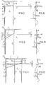
- the ground 2 exerts a pressure on the screen 4 opposite the pressure of the water 8, whereas the screen is retained by ground anchors 6 having a tractive force P.
- Fig. 2 illustrates the line of moments due to the forces exerted on the screen 4, the line of moments being designated at the area of the anchor heads 51 by M a , the maximum potential moment being designated by M max .
- the weight of the dam wall profiles 3 is a function of M max .
- ground retaining wall according to the invention is distinguished from the known ground retaining wall described above as follows.
- a wall 54 is standing at a distance b from the screen 4, said wall bearing on the part of the screen 4 located above the level A with the aid of pressure- transmitting supporting means 60.
- the space 14 between the standing wall 54 and the screen 4 is substantially free of ground and only contains air.
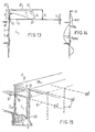
- the supporting means 60 may consist of a plurality of pressure bars of a framework, but preferably they are formed by reinforced concrete cover plates 10 having longitudinal ribs 57 engaging the top edges 58 and 59 of the dam wall profiles 3 and of the wall 54 respectively.
- the wall 54 is standing on a concrete foundation 13 and retains the top layer 55 of the ground 2.
- the pressure q exerted by the top layer 55 on the wall 54 is balanced out by the pressure force K of the supporting means 60 and the tensile force S of the anchor cables 9, which connect anchor heads 61 with the ground anchors 6. Owing to the application of the force K the line of moments of Fig. 4 is obtained, where M max is considerably lower than that of Fig. 3. Moreover, owing to the ground-free space 14 the overall pressure of the ground 2 to be retained is appreciably reduced. As a result the dam wall profiles 3 of the screen 4 in Fig. 3 may be of considerably lighter weight than those of Fig. 1.
- the ground retaining wall 15 of Fig. 5 is distinguished from that of Fig. 3 in that the standing wall 63, the cover plates 64 as well as the foundation slabs 65 of the wall 63 form part of reinforced concrete longitudinal profiles 66, which are deposited on the dam wall profiles 3 and engage by a rib 67 the top edges 58.
- the cover slabs 64 are located in this example at a lower level than the top surface 68 of the ground 2, so that the dam wall profiles are shorter.
- the ground retaining wall 17 of Fig. 7 is distinguished from the ground retaining wall 15 in that the longitudinal profiles 18 are substantially L-shaped and the foundation of the standing wall 70 is formed by piles 20.
- the ground retaining wall 19 of Fig. 9 is distinguished from that of Fig. 7 in that the ground-free space 14 is enlarged by leaving out ground in a space 71 below the water level 72, as a result of which the ground pressure to be retained is further reduced.
- anchor means 51, 5 and 6 are arranged above the level of the water 8, which is usually required for these anchor means.
- the screen 4 may, as an alternative, consist of a reinforced concrete wall or concrete wall elements.
Landscapes
- Engineering & Computer Science (AREA)
- General Engineering & Computer Science (AREA)
- Civil Engineering (AREA)
- Environmental & Geological Engineering (AREA)
- Structural Engineering (AREA)
- Mining & Mineral Resources (AREA)
- Paleontology (AREA)
- General Life Sciences & Earth Sciences (AREA)
- Life Sciences & Earth Sciences (AREA)
- Ocean & Marine Engineering (AREA)
- Mechanical Engineering (AREA)
- Road Paving Structures (AREA)
- Investigation Of Foundation Soil And Reinforcement Of Foundation Soil By Compacting Or Drainage (AREA)
- Pit Excavations, Shoring, Fill Or Stabilisation Of Slopes (AREA)
- Soil Working Implements (AREA)
- Revetment (AREA)
- Retaining Walls (AREA)
Claims (4)
Priority Applications (3)
| Application Number | Priority Date | Filing Date | Title |
|---|---|---|---|
| DE8080200982T DE3066623D1 (en) | 1980-10-16 | 1980-10-16 | Ground retaining wall |
| AT80200982T ATE6280T1 (de) | 1980-10-16 | 1980-10-16 | Stuetzmauer. |
| EP80200982A EP0050166B1 (de) | 1980-10-16 | 1980-10-16 | Stützmauer |
Applications Claiming Priority (1)
| Application Number | Priority Date | Filing Date | Title |
|---|---|---|---|
| EP80200982A EP0050166B1 (de) | 1980-10-16 | 1980-10-16 | Stützmauer |
Publications (2)
| Publication Number | Publication Date |
|---|---|
| EP0050166A1 EP0050166A1 (de) | 1982-04-28 |
| EP0050166B1 true EP0050166B1 (de) | 1984-02-15 |
Family
ID=8187042
Family Applications (1)
| Application Number | Title | Priority Date | Filing Date |
|---|---|---|---|
| EP80200982A Expired EP0050166B1 (de) | 1980-10-16 | 1980-10-16 | Stützmauer |
Country Status (3)
| Country | Link |
|---|---|
| EP (1) | EP0050166B1 (de) |
| AT (1) | ATE6280T1 (de) |
| DE (1) | DE3066623D1 (de) |
Families Citing this family (2)
| Publication number | Priority date | Publication date | Assignee | Title |
|---|---|---|---|---|
| ES2091704B1 (es) * | 1993-07-23 | 1998-04-16 | Fospas S L | Muro prefabricado de hormigon armado, anclado, de tension controlada. |
| DE10252452B4 (de) | 2002-11-12 | 2006-07-06 | Clariant Gmbh | Styroloxidhaltige Copolymere und deren Verwendung als Emulgatoren und Dispergiermittel |
Citations (5)
| Publication number | Priority date | Publication date | Assignee | Title |
|---|---|---|---|---|
| BE380552A (de) * | ||||
| BE414100A (de) * | ||||
| DE561822C (de) * | 1930-05-24 | 1932-10-19 | Alfons Schroeter | Stuetzwand fuer Erd- und sonstigen Hinterfuellungsstoff |
| FR737124A (de) * | 1932-12-06 | |||
| DE1209067B (de) * | 1962-08-18 | 1966-01-13 | Hoerder Huettenunion Ag | Zur Abstuetzung eines Gelaendesprunges dienende, rueckseitig verankerte Spundwand |
Family Cites Families (1)
| Publication number | Priority date | Publication date | Assignee | Title |
|---|---|---|---|---|
| FR339355A (fr) * | 1903-01-06 | 1904-06-08 | Jean Henri Delleur | Perfectionnements dans la construction des murs de quai, murs de soutènement, revetements de talus et autres murs analogues |
-
1980
- 1980-10-16 AT AT80200982T patent/ATE6280T1/de active
- 1980-10-16 DE DE8080200982T patent/DE3066623D1/de not_active Expired
- 1980-10-16 EP EP80200982A patent/EP0050166B1/de not_active Expired
Patent Citations (5)
| Publication number | Priority date | Publication date | Assignee | Title |
|---|---|---|---|---|
| BE380552A (de) * | ||||
| BE414100A (de) * | ||||
| FR737124A (de) * | 1932-12-06 | |||
| DE561822C (de) * | 1930-05-24 | 1932-10-19 | Alfons Schroeter | Stuetzwand fuer Erd- und sonstigen Hinterfuellungsstoff |
| DE1209067B (de) * | 1962-08-18 | 1966-01-13 | Hoerder Huettenunion Ag | Zur Abstuetzung eines Gelaendesprunges dienende, rueckseitig verankerte Spundwand |
Also Published As
| Publication number | Publication date |
|---|---|
| ATE6280T1 (de) | 1984-03-15 |
| DE3066623D1 (en) | 1984-03-22 |
| EP0050166A1 (de) | 1982-04-28 |
Similar Documents
| Publication | Publication Date | Title |
|---|---|---|
| US8621802B2 (en) | Brick bracket for installation of a ledger on the brick facing or veneer of a structure and associated methods for the installation of the brick bracket on the brick facing | |
| US3381483A (en) | Sea wall and panel construction | |
| US3316721A (en) | Tensioned retaining wall for embankment | |
| KR950011723B1 (ko) | 흙 구조물(earth structures) | |
| US3848378A (en) | Stairs for swimming pools | |
| US4000622A (en) | Shoring structure for embankments | |
| GB1597319A (en) | Wall system of constructional units | |
| EP0564515A1 (de) | Böschungsmauer. | |
| US4078350A (en) | Impact resistant wall structure | |
| EP0050166A1 (de) | Stützmauer | |
| US4293245A (en) | Structural system and structural elements for use and construction of earth filled walls | |
| JP2021188450A (ja) | ホームドア設置構造 | |
| EP0514559B1 (de) | Übertragung der Last eines Gebäudes über Stahlträger auf das Umland durch den Einsatz eines Spezialfallbären | |
| CN211113733U (zh) | 拉锚式自平衡挡土板 | |
| CN210263041U (zh) | 锚杆内置锁定结构 | |
| US3340664A (en) | Concrete structure with butt spliced compression and tension reinforcement | |
| SU1067148A1 (ru) | Устройство дл выравнивани зданий,сооружений | |
| GB1592364A (en) | Building construction | |
| JPH10140582A (ja) | 耐震基礎及びその施工法 | |
| GB2062079A (en) | Precast Wall Unit for Silage Pit or Tank | |
| SU1276750A1 (ru) | Камера судоходного шлюза | |
| EP0026782B1 (de) | Erdreich- und wasserschutzmauer, die aus vorgefertigten plattenelementen zusammengesetzt ist | |
| SU981512A1 (ru) | Сейсмостойкий фундамент здани ,сооружени ,оборудовани | |
| SU1625917A1 (ru) | Набережна | |
| SU844656A1 (ru) | Противофильтрационное покрытиедл гидРОТЕХНичЕСКиХ СООРужЕНий |
Legal Events
| Date | Code | Title | Description |
|---|---|---|---|
| PUAI | Public reference made under article 153(3) epc to a published international application that has entered the european phase |
Free format text: ORIGINAL CODE: 0009012 |
|
| 17P | Request for examination filed |
Effective date: 19811001 |
|
| AK | Designated contracting states |
Designated state(s): AT BE CH DE FR GB IT LU NL SE |
|
| GRAA | (expected) grant |
Free format text: ORIGINAL CODE: 0009210 |
|
| AK | Designated contracting states |
Designated state(s): AT BE CH DE FR GB IT LI LU NL SE |
|
| PG25 | Lapsed in a contracting state [announced via postgrant information from national office to epo] |
Ref country code: SE Effective date: 19840215 Ref country code: LI Effective date: 19840215 Ref country code: IT Free format text: LAPSE BECAUSE OF FAILURE TO SUBMIT A TRANSLATION OF THE DESCRIPTION OR TO PAY THE FEE WITHIN THE PRESCRIBED TIME-LIMIT;WARNING: LAPSES OF ITALIAN PATENTS WITH EFFECTIVE DATE BEFORE 2007 MAY HAVE OCCURRED AT ANY TIME BEFORE 2007. THE CORRECT EFFECTIVE DATE MAY BE DIFFERENT FROM THE ONE RECORDED. Effective date: 19840215 Ref country code: FR Free format text: THE PATENT HAS BEEN ANNULLED BY A DECISION OF A NATIONAL AUTHORITY Effective date: 19840215 Ref country code: CH Effective date: 19840215 Ref country code: AT Effective date: 19840215 |
|
| REF | Corresponds to: |
Ref document number: 6280 Country of ref document: AT Date of ref document: 19840315 Kind code of ref document: T |
|
| REF | Corresponds to: |
Ref document number: 3066623 Country of ref document: DE Date of ref document: 19840322 |
|
| REG | Reference to a national code |
Ref country code: CH Ref legal event code: PL |
|
| EN | Fr: translation not filed | ||
| PG25 | Lapsed in a contracting state [announced via postgrant information from national office to epo] |
Ref country code: LU Free format text: LAPSE BECAUSE OF NON-PAYMENT OF DUE FEES Effective date: 19841031 |
|
| PLBI | Opposition filed |
Free format text: ORIGINAL CODE: 0009260 |
|
| 26 | Opposition filed |
Opponent name: BILFINGER + BERGER BAUAKTIENGESELLSCHAFT Effective date: 19841109 |
|
| NLR1 | Nl: opposition has been filed with the epo |
Opponent name: BERGER BAUAKTIENGESELLSCHAFT Opponent name: BILFINGER |
|
| PLBN | Opposition rejected |
Free format text: ORIGINAL CODE: 0009273 |
|
| STAA | Information on the status of an ep patent application or granted ep patent |
Free format text: STATUS: OPPOSITION REJECTED |
|
| 27O | Opposition rejected |
Effective date: 19860124 |
|
| NLR2 | Nl: decision of opposition | ||
| PGFP | Annual fee paid to national office [announced via postgrant information from national office to epo] |
Ref country code: GB Payment date: 19931011 Year of fee payment: 14 |
|
| PGFP | Annual fee paid to national office [announced via postgrant information from national office to epo] |
Ref country code: BE Payment date: 19931020 Year of fee payment: 14 |
|
| PGFP | Annual fee paid to national office [announced via postgrant information from national office to epo] |
Ref country code: DE Payment date: 19931029 Year of fee payment: 14 |
|
| PGFP | Annual fee paid to national office [announced via postgrant information from national office to epo] |
Ref country code: NL Payment date: 19931031 Year of fee payment: 14 |
|
| PG25 | Lapsed in a contracting state [announced via postgrant information from national office to epo] |
Ref country code: GB Effective date: 19941016 |
|
| PG25 | Lapsed in a contracting state [announced via postgrant information from national office to epo] |
Ref country code: BE Effective date: 19941031 |
|
| BERE | Be: lapsed |
Owner name: BALLAST-NEDAM GROEP N.V. Effective date: 19941031 |
|
| PG25 | Lapsed in a contracting state [announced via postgrant information from national office to epo] |
Ref country code: NL Effective date: 19950501 |
|
| GBPC | Gb: european patent ceased through non-payment of renewal fee |
Effective date: 19941016 |
|
| NLV4 | Nl: lapsed or anulled due to non-payment of the annual fee | ||
| PG25 | Lapsed in a contracting state [announced via postgrant information from national office to epo] |
Ref country code: DE Effective date: 19950701 |