EP0050233A2 - Meule diamantée pour l'usinage de pierre - Google Patents
Meule diamantée pour l'usinage de pierre Download PDFInfo
- Publication number
- EP0050233A2 EP0050233A2 EP81107561A EP81107561A EP0050233A2 EP 0050233 A2 EP0050233 A2 EP 0050233A2 EP 81107561 A EP81107561 A EP 81107561A EP 81107561 A EP81107561 A EP 81107561A EP 0050233 A2 EP0050233 A2 EP 0050233A2
- Authority
- EP
- European Patent Office
- Prior art keywords
- grinding wheel
- wheel according
- carrier
- coolant
- diamond
- Prior art date
- Legal status (The legal status is an assumption and is not a legal conclusion. Google has not performed a legal analysis and makes no representation as to the accuracy of the status listed.)
- Granted
Links
Images


Classifications
-
- B—PERFORMING OPERATIONS; TRANSPORTING
- B24—GRINDING; POLISHING
- B24D—TOOLS FOR GRINDING, BUFFING OR SHARPENING
- B24D7/00—Bonded abrasive wheels, or wheels with inserted abrasive blocks, designed for acting otherwise than only by their periphery, e.g. by the front face; Bushings or mountings therefor
- B24D7/10—Bonded abrasive wheels, or wheels with inserted abrasive blocks, designed for acting otherwise than only by their periphery, e.g. by the front face; Bushings or mountings therefor with cooling provisions
Definitions
- the invention relates to a diamond grinding wheel for stone processing, in particular by means of a hand-held grinding machine, consisting of a support to be placed on the drive spindle and provided with a central coolant bore and a ring-shaped coating of bonded diamond grain connected to the latter, which forms the grinding surface, and the guide grooves for the coolant that are inclined in the circumferential direction having.
- Such grinding wheels are used in stone processing, in particular for breaking edges, for grinding lettering and for grinding smaller surfaces.
- the Diamantkom is generally embedded in a sintered metal powder and the covering formed in this way is glued or soldered to a carrier disc, which in turn is attached to the carrier of the grinding disc. Since it is wet grinding, precautions must be taken to ensure that on the one hand the engaging surface of the tool is always wetted with coolant is, on the other hand, the abrasive sludge that forms is removed.
- the shape of the grinding wheel must be designed in such a way that an optimal grinding performance is obtained with reasonable effort on the machine.
- the covering consists of two narrow rings, of which the outer is arranged concentrically to the carrier disk, the inner, however, is arranged eccentrically (DE-PS 1 270 982).
- This grinding wheel has the disadvantage that it easily runs out of the working position due to the eccentric arrangement of the inner ring. Due to the narrow design of the rings and the eccentric arrangement of the inner ring, the engagement surface of the tool is also relatively small.
- a narrow outer ring concentric with the carrier disk is also provided.
- the eccentric inner ring of the abovementioned grinding wheel is replaced by a plurality of ring segments which run outwards from the center of the carrier wheel and are otherwise curved in the circumferential direction. Due to the symmetrical arrangement of these ring segments, this grinding wheel does not run out, but has the disadvantage that it can get stuck on the ring segments due to the many edges, the surface to be machined is ground unevenly or even these edges break out on the workpiece.
- the ring-shaped grinding surface is simply widened in order to increase performance, this requires, as already indicated, a higher pressing force, since a larger proportion of diamond grain is engaged per unit of time.
- Certain improvements can be achieved in that a combed softer material, e.g. Coal particles are embedded, which are removed or broken out during the grinding process and thus lead to a porous surface. This reduces the engagement surface despite the large grinding surface (large ring width).
- this construction which is advantageous in terms of the technical concept, offers considerable difficulties in terms of production technology.
- the invention is based on the object Propose training in which, on the one hand, uneven wear does not occur and, on the other hand, the addition of soft particles to the sintered mass is not necessary.
- the covering between the coolant guide grooves has recesses formed during its manufacture, which are designed so that when the grinding surface engages the workpiece, coolant cannot pass from the center to the outside.
- the depressions provided according to the invention lead to a reduction in the effective grinding area, so that conversely the width of the annular covering and thus the area on the workpiece which is covered by the grinding wheel can be relatively large. Any unbalance can be avoided by a symmetrical arrangement of the depressions, also in connection with the coolant guide grooves. Likewise, this and an optimization of the ratio of the ring width to the free surface of the depressions prevent uneven wear of the grinding surface. Finally, by shaping and arranging the depressions, the circumferential speed of the grinding surface that changes over the ring width can be taken into account.
- the bond of the diamond core is usually achieved by sintering a metal powder, the covering having two layers, of which only the later outer layer contains the diamond, while the layer later forming the back of the covering is free of diamond.
- Sintem takes place in a shape adapted to the outline of the covering, so that the grooves and the depressions can easily be replaced by corresponding shaped pieces which are inserted into the sintered shape. have it molded in when the topping is made.
- the covering consists of a plurality of sector-shaped sections, which are embedded in a ring-shaped arrangement with formation of the coolant guide grooves and the depressions in a rubber-elastic compound, and a disk carrying the investment compound, which is connected to the carrier .
- the procedure in this embodiment is that first the enclosed ring is produced with the two layers in a conventional manner, then the ring is separated into the sector-shaped sections and finally these are cast in an annular mold with the investment material. At the same time, the supporting disc can be pressed into the investment or attached later, e.g. be glued.
- each individual sector-shaped section is elastically supported, so it can deflect when pressed onto the workpiece. In this way, hollow grinding work can be carried out without difficulty. At the same time, this elastic mounting of the abrasive coating is perceived by the user as pleasant.
- the depressions are designed such that they allow the coolant to pass through from the inside prevent outside. If the wells are formed as grooves, it is provided see that these grooves are closed at least on the outer and / or inner edge of the annular covering up to the level of the grinding surface. It is therefore not a matter of continuous grooves, but rather of groove-shaped depressions which, on the one hand, act as a kind of pockets and thus retain the coolant, on the other hand prevent the coolant from being discharged to the outside too quickly.
- the same effect can be achieved in that the depressions are filled with a mass which is softer than the covering, for example the filling mass can consist of a pourable plastic. It will be advantageous to choose a plastic that does not "smear" even under heat. In the embodiment with the sector-shaped sections, this filling compound can be formed directly by the investment compound.
- This exemplary embodiment also gives the possibility of coloring the filling compound differently in accordance with the grain size of the covering. So far, grinding wheels of the type in question have been used for coarse, fine and ultra-fine grinding, as well as for polishing, the diamond grain being adapted to this particular application. In order to make these different grain sizes optically visible, the entire carrier has been colored differently. In the case of the grinding wheel designed according to the invention, this coloring can take place additionally or exclusively in the filling compound, the latter offering the advantage that the grain is actually only signaled on the grinding surface, but the carrier has a uniform color, so that confusion is not possible.
- the investment material advantageously consists of a cold pourable plastic, e.g. based on polyurethane, which makes the grinding wheel particularly easy to manufacture.
- the covering is designed as a separate washer, which is detachably attached to the carrier and centered on a pin of the carrier by means of a central recess and at the same time is secured against rotation.
- This design has the advantage that when the tool is changed, not the entire carrier, which is generally seated on the drive spindle with a thread, but only the covering has to be loosened. This initially results in a reduction in price, since only one carrier is required for a large number of coverings.
- this embodiment has the advantage that the carrier, which sticks to the drive spindle in particular after a long period of operation, no longer has to be loosened.
- the ring disk is held magnetically on the carrier.
- a magnetic holder cannot get stuck even after a long period of operation; rather, only the same force needs to be applied to release it.
- the magnetic holding force can be designed so that the covering is held sufficiently firmly by the carrier and cannot be thrown off by jerky movements of the grinding machine, but on the other hand can optionally be lifted off by means of a tensile force using a tool.
- the covering can have a separate layer made of a ferromagnetic material, which in the embodiment with the sector-shaped sections is formed, for example, by the carrier disk.
- the holding magnet is arranged on the carrier, for example it has one or more on its end face facing the covering embedded permanent magnets.
- a conventional coolant hole has a central coolant hole in the carrier.
- the coolant bore is generally covered on its exit side by a baffle plate, so that the coolant is distributed to the outside.
- a central centering pin is provided, which makes it more difficult to attach a baffle plate because of the canting that occurs as a result. It is therefore provided according to a further exemplary embodiment that the centering pin on the carrier is provided with two eccentrically arranged coolant bores which are connected to the central coolant bore. Due to the eccentric arrangement of the two coolant holes, the coolant is properly distributed.
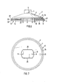
- the grinding wheel 1 consists, for example, of a cast metal carrier 2 in the form of a plate and a covering 3 which is detachably fastened to the end face thereof can be attached to a hand grinder.
- the attachment 4 has on the outside at least two diametrically opposite flats 5 for the attack of a wrench.
- the central threaded bore serves in a known and therefore not shown manner for the supply of a coolant.
- permanent magnets 7 are embedded in the end face 6 (see FIG. 2) of the carrier 2, three of which are provided in the embodiment shown.
- the end face 6 of the carrier 2 is surmounted by a central centering pin 8, on which the coolant line in the attachment 5 opens out via two eccentric bores 9.
- a further bore 10 is provided eccentrically in the end face 6 of the carrier 2.
- the covering 3, which is the actual tool, is produced, for example, from a metal powder by sintem, with diamond metal being embedded in the metal powder.
- the covering 3 is designed as a wide ring, which is centered with its central, in this case circular recess 11 on the pin 8 of the carrier 2. Furthermore, the covering 3 has on its rear side a molded-on pin 12 which engages in the bore 10 on the carrier 2 and thus secures the covering 3 against rotation. In the position shown in FIG. 1, the washer 3 and the annular disc are held on the carrier 2 by means of the permanent magnets 7.
- FIG. 3 which shows a view of the grinding surface of the covering 3, two embodiments of the grinding surface are shown in the upper and lower half.
- the covering 3 has a small number - in the exemplary embodiment shown three - guide grooves 14 which start from the central recess 11 and extend to the outer circumference of the covering 3. They serve to distribute the coolant emerging at the bores 9 of the centering pin of the carrier 2 (FIG. 1) over the grinding surface 13 and at the same time to remove the grinding sludge.
- Between the coolant guide grooves 14 are several - in the embodiment shown between two guide grooves each three - depressions in the form of grooves 15 which - like the coolant guide grooves 14 - are inclined in the circumferential direction.
- the grooves 15 are made with a comparatively soft filling compound, e.g. a plastic potting compound 16 filled up to the level of the grinding surface 13 so that coolant cannot migrate from the central recess 11 in the area of these grooves 15 to the outside.
- a comparatively soft filling compound e.g. a plastic potting compound 16 filled up to the level of the grinding surface 13 so that coolant cannot migrate from the central recess 11 in the area of these grooves 15 to the outside.
- the grooves 15 are instead closed only at their outer ends 17 and at their inner ends 18, so that a direct passage of coolant from the central recess 11 to the outer circumference of the lining 3rd not possible.
- the grooves 15 can also be closed at only one, preferably the outer end 17. This embodiment has the advantage that the coolant is stored in the grooves 15 so that a wet running of the grinding wheel is always ensured.
- a mechanical fastening in the form of head bolts 19 is provided, which are locked in curved recesses 20 by rotating lining 3 and carrier 2.
- the grooves 20 have circular extensions 21 for inserting the bolt head.
- a covering 3 can also be seen, which consists of two layers 22, 23, of which the layer 22 forming the grinding surface 13 contains the diamond bond, while the layer 23 has the fastening means - here the head bolts 19.
- the layer 23 consists of a ferromagnetic material.
- the end face 6 of the carrier 2 is surmounted by a central centering pin 8, which in this exemplary embodiment has two diametrically arranged flats 25.
- the coolant line in turn opens out via two eccentric holes 9.
- the abrasive coating 3 is designed as a wide ring and consists of a plurality of sector-shaped sections 26 (FIG. 8) which are fixed in an investment material 27, for example by casting. They are arranged in the investment material 27 in the form of a ring at a distance from one another.
- the continuous coolant guide grooves 14 are formed on the one hand, and on the other hand a plurality of groove-shaped depressions 15 are formed which, as shown in the upper illustration in FIG.
- the investment 27 is seated on a support disk 29 (FIG. 6) made of a ferromagnetic material, which has a recess 28 in the center, which corresponds to the centering pin 8 on the carrier 2.
Landscapes
- Engineering & Computer Science (AREA)
- Mechanical Engineering (AREA)
- Polishing Bodies And Polishing Tools (AREA)
Priority Applications (1)
| Application Number | Priority Date | Filing Date | Title |
|---|---|---|---|
| AT81107561T ATE13025T1 (de) | 1980-10-22 | 1981-09-23 | Diamantschleifscheibe fuer die steinbearbeitung. |
Applications Claiming Priority (4)
| Application Number | Priority Date | Filing Date | Title |
|---|---|---|---|
| DE3039755 | 1980-10-22 | ||
| DE3039755 | 1980-10-22 | ||
| DE3123548 | 1981-06-13 | ||
| DE3123548 | 1981-06-13 |
Publications (3)
| Publication Number | Publication Date |
|---|---|
| EP0050233A2 true EP0050233A2 (fr) | 1982-04-28 |
| EP0050233A3 EP0050233A3 (en) | 1983-02-23 |
| EP0050233B1 EP0050233B1 (fr) | 1985-05-02 |
Family
ID=25788630
Family Applications (1)
| Application Number | Title | Priority Date | Filing Date |
|---|---|---|---|
| EP19810107561 Expired EP0050233B1 (fr) | 1980-10-22 | 1981-09-23 | Meule diamantée pour l'usinage de pierre |
Country Status (2)
| Country | Link |
|---|---|
| EP (1) | EP0050233B1 (fr) |
| CA (1) | CA1181592A (fr) |
Cited By (7)
| Publication number | Priority date | Publication date | Assignee | Title |
|---|---|---|---|---|
| EP0177337A1 (fr) * | 1984-10-05 | 1986-04-09 | John J. Hogue | Moyeu porte-meule à béton |
| US4870946A (en) * | 1987-05-07 | 1989-10-03 | Longco, Inc. | Fluid-cooled apparatus for cutting concrete material and the like |
| US5959290A (en) * | 1998-01-08 | 1999-09-28 | Xerox Corporation | Image input device and method for providing scanning artifact detection |
| GB2345255A (en) * | 1998-12-29 | 2000-07-05 | United Microelectronics Corp | Chemical-mechanical polishing pad. |
| EP2228173B1 (fr) * | 2009-03-14 | 2014-09-10 | Boris Dipl.-Ing. Kochanski | Dispositif de polissage ou d'affilage avec un actionnement par air comprimé |
| WO2016116452A1 (fr) * | 2015-01-20 | 2016-07-28 | Htc Sweden Ab | Disque de support, système comprenant un tel disque de support et machine de polissage de sol |
| US10919127B2 (en) | 2016-10-17 | 2021-02-16 | Matuschek Messtechnik Gmbh | Grinding wheel |
Families Citing this family (1)
| Publication number | Priority date | Publication date | Assignee | Title |
|---|---|---|---|---|
| EP4360805A1 (fr) | 2022-10-24 | 2024-05-01 | Gühring KG | Disque abrasif |
Family Cites Families (9)
| Publication number | Priority date | Publication date | Assignee | Title |
|---|---|---|---|---|
| DE1066449B (fr) * | 1959-10-01 | |||
| US2078120A (en) * | 1933-03-27 | 1937-04-20 | Norton Co | Grinding disk |
| US2056182A (en) * | 1934-02-08 | 1936-10-06 | Gardner Machine Co | Grinding machine |
| US2092978A (en) * | 1934-12-05 | 1937-09-14 | Norton Co | Grinding disk |
| US2425368A (en) * | 1945-04-06 | 1947-08-12 | Titan Abrasives Company | Abrasive disk unit |
| GB704269A (en) * | 1951-07-19 | 1954-02-17 | Pilkington Brothers Ltd | Improvements in and relating to the grinding of plate glass |
| DE1195632B (de) * | 1954-09-08 | 1965-06-24 | Glaceries De La Sambre Sa | Einrichtung zur Foerderung und Verteilung des Bearbeitungsmittels fuer ein Werkzeug zum Bearbeiten eines Glasbandes |
| BE547473A (fr) * | 1955-05-03 | |||
| US3386214A (en) * | 1965-09-01 | 1968-06-04 | Titan Abrasives Company | Grinding disc |
-
1981
- 1981-09-23 EP EP19810107561 patent/EP0050233B1/fr not_active Expired
- 1981-10-21 CA CA000388434A patent/CA1181592A/fr not_active Expired
Cited By (12)
| Publication number | Priority date | Publication date | Assignee | Title |
|---|---|---|---|---|
| EP0177337A1 (fr) * | 1984-10-05 | 1986-04-09 | John J. Hogue | Moyeu porte-meule à béton |
| US4870946A (en) * | 1987-05-07 | 1989-10-03 | Longco, Inc. | Fluid-cooled apparatus for cutting concrete material and the like |
| US5959290A (en) * | 1998-01-08 | 1999-09-28 | Xerox Corporation | Image input device and method for providing scanning artifact detection |
| GB2345255A (en) * | 1998-12-29 | 2000-07-05 | United Microelectronics Corp | Chemical-mechanical polishing pad. |
| US6120366A (en) * | 1998-12-29 | 2000-09-19 | United Microelectronics Corp. | Chemical-mechanical polishing pad |
| GB2345255B (en) * | 1998-12-29 | 2000-12-27 | United Microelectronics Corp | Chemical-Mechanical Polishing Pad |
| EP2228173B1 (fr) * | 2009-03-14 | 2014-09-10 | Boris Dipl.-Ing. Kochanski | Dispositif de polissage ou d'affilage avec un actionnement par air comprimé |
| WO2016116452A1 (fr) * | 2015-01-20 | 2016-07-28 | Htc Sweden Ab | Disque de support, système comprenant un tel disque de support et machine de polissage de sol |
| CN107405751A (zh) * | 2015-01-20 | 2017-11-28 | 赫特先瑞典股份公司 | 支座盘、包括这种支座盘的系统和地板研磨机 |
| US9931734B2 (en) | 2015-01-20 | 2018-04-03 | Htc Sweden Ab | Carrier disk, system comprising such carrier disk and floor grinding machine |
| CN107405751B (zh) * | 2015-01-20 | 2019-07-05 | 胡斯华纳有限公司 | 支座盘、包括这种支座盘的系统和地板研磨机 |
| US10919127B2 (en) | 2016-10-17 | 2021-02-16 | Matuschek Messtechnik Gmbh | Grinding wheel |
Also Published As
| Publication number | Publication date |
|---|---|
| CA1181592A (fr) | 1985-01-29 |
| EP0050233A3 (en) | 1983-02-23 |
| EP0050233B1 (fr) | 1985-05-02 |
Similar Documents
| Publication | Publication Date | Title |
|---|---|---|
| DE68919908T2 (de) | Schleifscheibe mit hoher Schlagfestigkeit zum in-situ-Schleifen von Rollen. | |
| DE20023967U1 (de) | Elektrohandschleifmaschine, insbesondere Exzenterschleifer | |
| EP1321233A1 (fr) | Outil de polissage | |
| EP0050233A2 (fr) | Meule diamantée pour l'usinage de pierre | |
| DE2350405B2 (de) | Scheibenförmiges Lappwerkzeug | |
| DE4424203C2 (de) | Schleifscheibe zum Schleifen des Randes von Brillengläsern | |
| DE2931695C2 (de) | Schleifkörper zum Vor- und Nachschleifen | |
| DE69903709T2 (de) | Schleifscheibe | |
| DE2331646A1 (de) | Schleifkoerper | |
| DE3138616A1 (de) | Diamantschleifscheibe fuer die steinbearbeitung | |
| DE3623408A1 (de) | Schleifwerkzeug, insbesondere schleifstift | |
| EP1207010B1 (fr) | Machine de meulage | |
| DE7530623U (de) | Segment-schleifkopf | |
| DE890911C (de) | Schleifscheibe | |
| DE4334887C2 (de) | Verwendung eines Schleifwerkzeugs zum Bearbeiten des Umfangsrandes und/oder deroptischen Oberfläche von Brillengläsern aus Kunststoff | |
| DE8028118U1 (de) | Diamantschleifscheibe fuer die steinbearbeitung | |
| DE4235281C1 (de) | Schleifwerkzeug aus flexiblem grundmaterial, insbesondere zum schleifen von unebenen flaechen, welches als schuh oder handschuh ausgebildet ist | |
| DE1652887A1 (de) | Trenn-,Schneid- und Schleifscheibe zur Bearbeitung von Metall oder Stein | |
| DE7306787U (de) | Schleifscheibe | |
| DE102004005627A1 (de) | Schleifgerät, insbesondere zum Schleifen von Natur- und Kunststein | |
| EP0067402B1 (fr) | Tête porte-meule pour roche dure | |
| DE10147822C2 (de) | Polierscheibe oder Polierwalze | |
| DE9103254U1 (de) | Flaschendrehteller | |
| DE4412322C1 (de) | Topfschleifscheibe | |
| DE8117582U1 (de) | Diamantschleifscheibe fuer die steinbearbeitung |
Legal Events
| Date | Code | Title | Description |
|---|---|---|---|
| PUAI | Public reference made under article 153(3) epc to a published international application that has entered the european phase |
Free format text: ORIGINAL CODE: 0009012 |
|
| AK | Designated contracting states |
Designated state(s): AT BE CH FR GB IT LI NL SE |
|
| RAP1 | Party data changed (applicant data changed or rights of an application transferred) |
Owner name: J. KOENIG GMBH & CO. WERKZEUGFABRIK, STEININDUSTR |
|
| PUAL | Search report despatched |
Free format text: ORIGINAL CODE: 0009013 |
|
| AK | Designated contracting states |
Designated state(s): AT BE CH FR GB IT LI NL SE |
|
| RAP1 | Party data changed (applicant data changed or rights of an application transferred) |
Owner name: J. KOENIG GMBH & CO. WERKZEUGFABRIK, STEININDUSTR |
|
| 17P | Request for examination filed |
Effective date: 19830603 |
|
| ITF | It: translation for a ep patent filed | ||
| GRAA | (expected) grant |
Free format text: ORIGINAL CODE: 0009210 |
|
| AK | Designated contracting states |
Designated state(s): AT BE CH FR GB IT LI NL SE |
|
| REF | Corresponds to: |
Ref document number: 13025 Country of ref document: AT Date of ref document: 19850515 Kind code of ref document: T |
|
| ET | Fr: translation filed | ||
| PLBE | No opposition filed within time limit |
Free format text: ORIGINAL CODE: 0009261 |
|
| STAA | Information on the status of an ep patent application or granted ep patent |
Free format text: STATUS: NO OPPOSITION FILED WITHIN TIME LIMIT |
|
| 26N | No opposition filed | ||
| PGFP | Annual fee paid to national office [announced via postgrant information from national office to epo] |
Ref country code: AT Payment date: 19860828 Year of fee payment: 6 |
|
| PGFP | Annual fee paid to national office [announced via postgrant information from national office to epo] |
Ref country code: NL Payment date: 19860930 Year of fee payment: 6 |
|
| PG25 | Lapsed in a contracting state [announced via postgrant information from national office to epo] |
Ref country code: NL Effective date: 19880401 |
|
| NLV4 | Nl: lapsed or anulled due to non-payment of the annual fee | ||
| PG25 | Lapsed in a contracting state [announced via postgrant information from national office to epo] |
Ref country code: GB Effective date: 19890923 Ref country code: AT Effective date: 19890923 |
|
| PG25 | Lapsed in a contracting state [announced via postgrant information from national office to epo] |
Ref country code: SE Effective date: 19890924 |
|
| ITTA | It: last paid annual fee | ||
| PG25 | Lapsed in a contracting state [announced via postgrant information from national office to epo] |
Ref country code: BE Effective date: 19890930 |
|
| BERE | Be: lapsed |
Owner name: J. KONIG G.M.B.H. & CO. WERKZEUGFABRIK STEININDU Effective date: 19890930 |
|
| GBPC | Gb: european patent ceased through non-payment of renewal fee | ||
| PGFP | Annual fee paid to national office [announced via postgrant information from national office to epo] |
Ref country code: FR Payment date: 19900831 Year of fee payment: 10 |
|
| PG25 | Lapsed in a contracting state [announced via postgrant information from national office to epo] |
Ref country code: FR Effective date: 19920529 |
|
| REG | Reference to a national code |
Ref country code: FR Ref legal event code: ST |
|
| EUG | Se: european patent has lapsed |
Ref document number: 81107561.3 Effective date: 19900521 |
|
| PGFP | Annual fee paid to national office [announced via postgrant information from national office to epo] |
Ref country code: CH Payment date: 19961202 Year of fee payment: 16 |
|
| PG25 | Lapsed in a contracting state [announced via postgrant information from national office to epo] |
Ref country code: LI Free format text: LAPSE BECAUSE OF NON-PAYMENT OF DUE FEES Effective date: 19970930 Ref country code: CH Free format text: LAPSE BECAUSE OF NON-PAYMENT OF DUE FEES Effective date: 19970930 |
|
| REG | Reference to a national code |
Ref country code: CH Ref legal event code: PL |