EP0050252A1 - Méthode et dispositif pour l'identification d'un patron de lignes de contraste sur des objets - Google Patents
Méthode et dispositif pour l'identification d'un patron de lignes de contraste sur des objets Download PDFInfo
- Publication number
- EP0050252A1 EP0050252A1 EP81107881A EP81107881A EP0050252A1 EP 0050252 A1 EP0050252 A1 EP 0050252A1 EP 81107881 A EP81107881 A EP 81107881A EP 81107881 A EP81107881 A EP 81107881A EP 0050252 A1 EP0050252 A1 EP 0050252A1
- Authority
- EP
- European Patent Office
- Prior art keywords
- signal
- line pattern
- pic
- interval
- contrast line
- Prior art date
- Legal status (The legal status is an assumption and is not a legal conclusion. Google has not performed a legal analysis and makes no representation as to the accuracy of the status listed.)
- Granted
Links
Images


Classifications
-
- G—PHYSICS
- G06—COMPUTING OR CALCULATING; COUNTING
- G06K—GRAPHICAL DATA READING; PRESENTATION OF DATA; RECORD CARRIERS; HANDLING RECORD CARRIERS
- G06K7/00—Methods or arrangements for sensing record carriers, e.g. for reading patterns
- G06K7/10—Methods or arrangements for sensing record carriers, e.g. for reading patterns by electromagnetic radiation, e.g. optical sensing; by corpuscular radiation
- G06K7/10544—Methods or arrangements for sensing record carriers, e.g. for reading patterns by electromagnetic radiation, e.g. optical sensing; by corpuscular radiation by scanning of the records by radiation in the optical part of the electromagnetic spectrum
- G06K7/10821—Methods or arrangements for sensing record carriers, e.g. for reading patterns by electromagnetic radiation, e.g. optical sensing; by corpuscular radiation by scanning of the records by radiation in the optical part of the electromagnetic spectrum further details of bar or optical code scanning devices
- G06K7/10861—Methods or arrangements for sensing record carriers, e.g. for reading patterns by electromagnetic radiation, e.g. optical sensing; by corpuscular radiation by scanning of the records by radiation in the optical part of the electromagnetic spectrum further details of bar or optical code scanning devices sensing of data fields affixed to objects or articles, e.g. coded labels
- G06K7/10871—Methods or arrangements for sensing record carriers, e.g. for reading patterns by electromagnetic radiation, e.g. optical sensing; by corpuscular radiation by scanning of the records by radiation in the optical part of the electromagnetic spectrum further details of bar or optical code scanning devices sensing of data fields affixed to objects or articles, e.g. coded labels randomly oriented data-fields, code-marks therefore, e.g. concentric circles-code
-
- G—PHYSICS
- G06—COMPUTING OR CALCULATING; COUNTING
- G06K—GRAPHICAL DATA READING; PRESENTATION OF DATA; RECORD CARRIERS; HANDLING RECORD CARRIERS
- G06K7/00—Methods or arrangements for sensing record carriers, e.g. for reading patterns
- G06K7/10—Methods or arrangements for sensing record carriers, e.g. for reading patterns by electromagnetic radiation, e.g. optical sensing; by corpuscular radiation
- G06K7/14—Methods or arrangements for sensing record carriers, e.g. for reading patterns by electromagnetic radiation, e.g. optical sensing; by corpuscular radiation using light without selection of wavelength, e.g. sensing reflected white light
-
- G—PHYSICS
- G06—COMPUTING OR CALCULATING; COUNTING
- G06V—IMAGE OR VIDEO RECOGNITION OR UNDERSTANDING
- G06V30/00—Character recognition; Recognising digital ink; Document-oriented image-based pattern recognition
- G06V30/10—Character recognition
- G06V30/22—Character recognition characterised by the type of writing
- G06V30/224—Character recognition characterised by the type of writing of printed characters having additional code marks or containing code marks
Definitions
- the invention relates to a method and a device for identifying objects which appear in any position and orientation and at any time on a picture window and which have a marking in the form of a data field on a surface facing the picture window which contains characters which contrast in at least one data track comprises at least one contrast line pattern which characterizes the position and the orientation of the data track and has several parallel lines with different spacing and / or line widths, the image window being scanned line by line and a binary video signal corresponding to the scanned contrast sequence being generated, the image window being in the first method step scanning at different angles until a contrast line pattern is recognized, the position and orientation of the data field relative to the image window is determined in the second method step, and in the third method step A raster scan is carried out in the direction of the data track and the characters contained in the data track are read and decoded.
- the objects to be identified are, for example, merchandise, department store articles or the like, which are marked in machine-readable form.
- markings are attached or attached to the objects, which are printed with signs of a machine-readable code, for example the OCR code.
- Such labeling can consist of quality, dimension, price information, the article number etc.
- This identification data is in some way affixed to the surfaces of the objects.
- markings are difficult to read by machine because the objects differ in their "size” and because these markings are applied, for example, to adhesive labels at different locations on the object.
- the data field on the object only appears more or less approximately at a certain location, and the alignment of the data field is also relatively arbitrary.
- Such methods and devices for identifying objects are used, for example, at the cash registers of supermarkets, etc., in order to enable automatic detection of the price and / or article number of the objects which a customer wishes to buy and for this purpose at the cash register brought Has.
- the goods such as boxes of different shapes and sizes, bottles, boxes, cans, etc.
- the data fields on the different objects thus appear differently aligned at different locations within the image window.
- the data fields do not appear at the reading station at fixed time intervals.
- the reading station must therefore search for the data field and then read out the characters of the data tracks in the direction of the data tracks of the data field.
- the read characters can then be sent to the till as electrical signals, which can print out the price and possibly also the article number or article group on the receipt.
- the data field applied to the object is provided with a contrast line pattern (PIC), which has several parallel lines with different distances and / or different line widths.
- the contrast line pattern is used to reliably and unambiguously differentiate the data field, for example the printed label, from other characters and line patterns which may be present on the surface of the object in the vicinity of the data field.
- the contrast line pattern has a predetermined position and orientation with respect to the data tracks within the data field and can therefore be used to determine the position and orientation of the contrast line pattern - and thus the data tracks - relative to the scanning angle of the scanning line, and subsequently a scanning grid in the direction of the data tracks to generate, which sweeps the characters within the data tracks in the vertical direction.
- the reliable detection of the contrast line pattern thus represents an essential step in the omnidirectional reading of such data fields that are printed with plain characters.
- blurred edges of the lines of the contrast line pattern become noticeable and may prevent a scanned contrast line pattern from being recognized as such, since the pulse sequence contained in the video signal differs from the stored comparison pattern. As a result, either the search process is repeated or the contrast line pattern cannot be recognized at all, the associated data field then remains unread.
- the object of the invention is to specify a method and a device of the type mentioned at the beginning, which enables a quick and reliable detection of contrast line patterns and works largely unaffected by blurring at the edges of the contrast lines.
- This object is achieved in a method of the type mentioned at the outset by measuring the interval length of overlapping light-dark intervals of the video signal in order to identify the contrast line pattern (PIC), comparing successively measured interval lengths and comparing a comparison signal with a first amplitude is generated when the two respectively compared interval lengths are in a predetermined relationship to one another, which corresponds to the corresponding distances of the contrast line pattern, and that a detection signal (PIC OUT) is emitted when a comparison signal is also present with a number of successive comparison steps predetermined by the contrast line pattern first amplitude is generated.
- PIC contrast line pattern
- a device for solving the task has an optoelectronic scanning device which emits a binary video signal at the output, which corresponds to a line-by-line image field and consists of a series of light-dark intervals.
- Such a device also contains decoding devices for recognizing a scanned contrast line pattern, which characterizes the position and the orientation of at least one data track of a data field, and contains several parallel lines with different spacing and / or line width.
- the device also includes means for aligning the Ab Tastraster parallel to the data track and for reading the characters of the data track scanned with the scanning grid.
- Such a device is characterized according to the invention in that the decoding devices contain a counting circuit which receives the video signal and the interval lengths of successively overlapping intervals of the video signal are counted, that the decoding devices contain at least one comparison table which receives successively counted interval lengths in pairs and in each case one Outputs comparison signal with the first amplitude when the two interval lengths compared with each other are in a predetermined ratio, which corresponds to the ratio of the corresponding intervals of the contrast line pattern, and that an evaluation circuit is provided which, in succession of a predetermined number of comparison signals with a first amplitude, a detection signal (PIC -OUT).
- the advantages of the invention are, in particular, that the detection of the contrast line pattern only depends on whether the ratio of successive, overlapping interval lengths of the video signal is within narrow value ranges, so that the contrast line pattern is reliable even when scanning obliquely to the direction of the contrast lines is recognized because the successively formed ratios of successively measured interval lengths of the video signal are invariant with respect to the scanning angle.
- the search for the contrast line pattern can therefore take place with relatively large angular steps, ie relatively quickly.
- the determination is made as to whether the ratio of successively measured interval lengths is within a predetermined value range, not by division, but by input into a two-dimensional comparison table, also called a division table, which only emits a comparison signal with a predetermined first amplitude if both of the interval lengths compared in each case lie in a predetermined expectation field of the table, within which the quotient of the interval lengths compared with one another has a value range which corresponds to that of the corresponds to the corresponding interval lengths of the contrast line pattern sought. This avoids the time-consuming and hardware-intensive division process and maintains the real-time operation with respect to the video signal in a simple manner.
- the comparison table is preferably designed as a two-dimensional read-only memory (PROM).
- PROM read-only memory
- the different possible discrete values of the first measured interval length address different lines of the read-only memory.
- the different discrete values of the interval length measured below are addressed by different columns of the read-only memory.
- the expectation field is specified so that it includes all those memory locations in which the quotient of the interval length assigned to the row address and the interval length assigned to the column address in is within a predetermined range of values. If a memory location is addressed within the expectation field, the read-only memory emits a comparison signal with a first amplitude, which signals partial recognition of the contrast line pattern.
- a comparison signal is emitted with a second amplitude, which signals that the quotient of the successive interval lengths compared lies outside the predetermined value range. If a comparison signal with a second amplitude occurs, the decoding devices are then reset and are then ready to carry out a new detection and decoding step.
- interval lengths to be compared are preferably entered in a separate comparison table with their own expectation field and checked there with respect to their quotient value.
- Each individual comparison table is preferably implemented as a separate read-only memory PROM in order to simplify the control logic of the decoding devices.
- the first read-only memory for comparing the first and second interval lengths, and the second read-only memory for comparing the second and third interval lengths, etc. have 8 bit memory locations. It is therefore possible to accommodate 8 comparison tables, each with its own expectation field, in the read-only memories, the first table being formed, for example, from the first bit of the memory locations, the second table from the second bit of the memory locations, etc. By Addressing the rows and columns of the read-only memory are addressed all 8 comparison tables at the same time. By selectively reading out each The table used can optionally identify up to 8 different contrast line patterns with a decoding circuit, which increases the usability of the device according to the invention.
- a first expectation field for corresponding interval lengths measured successively in the forward direction is particularly preferably provided for recognizing a specific contrast line pattern PIC.
- a second expectation field is specified for corresponding interval lengths measured successively in the backward direction.
- the contrast line pattern is scanned in the "forward direction” when the contrast lines are read out, for example, from left to right.
- the opposite direction is referred to as the "backward direction", in the backward direction the contrast lines are scanned in the opposite direction to the usual reading direction, ie from right to left.
- a detection signal PIC OUT V is emitted which indicates that the relevant contrast line pattern has been detected in the forward reading direction. If, on the other hand, the contrast line pattern is detected when scanning in the reverse direction, a second detection signal PIC OUT R is emitted, which is different from the first detection signal PIC OUT V.
- the search step for finding the contrast line pattern (1st method step) can be accelerated considerably in this way, and the number of angular steps halved, since the contrast line pattern is recognized in the forward or backward direction. The consequence of this is a considerable saving of time when carrying out a reading process.
- the specially used contrast line pattern can also contain information about the special structure of the character string used for the data tracks.
- a special contrast line pattern can always be used if only alpha characters, for example the article name etc., are printed in plain text in the first data track.
- Another special contrast line pattern can always be used if, for example, only the second data track is filled with alpha characters, for example the article name, etc.
- individual special contrast line patterns can be arranged in front of, behind or under the individual data tracks , which are always used when this data track has a certain, predetermined structure. If a specific contrast line pattern is recognized and the corresponding, individual PIC m -OUT signal is emitted, this signal can be used in the subsequent control circuit in order to carry out corresponding control processes for the structure of the data track in question.
- the PIC m -OUT signal - in the first example - can be used to activate an alpha character decoder for the first data track and then to activate a second decoder for numeric characters.
- the binary video signal has a first amplitude, Hi, when the scan beam is over a darkened area of the data field, and it has a second amplitude, Lo, when the scan beam is across a bright, character-free area of the data field.
- Hi first amplitude
- Lo second amplitude
- the intervals of the video signal preferably each extend from a rising edge to the next rising edge, and overlapping from the falling edge lying between these rising edges to the next falling edge of the video signal.
- the third interval then extends from the second rising edge to a next rising edge, etc.
- the fact that the intervals extend from rising edge to rising edge or from falling edge to falling edge ensures that blurred edges of the contrast lines of the contrast line pattern generally run in the same direction and in the same way for all contrast lines -. essentially do not influence the interval lengths, so that the decoding device according to the invention also recognizes contrast line patterns which were generated under different printing conditions.
- Contrast line patterns with a character-free lead zone can be used to increase recognition reliability Use the specified length, with the leading zone in front of the first contrast line.
- the interval lengths are preferably only measured when a character-free lead zone of the specified length appears in the video signal.
- the measurement of the interval lengths is preferably ended when any interval length exceeds a predetermined maximum value " which is equal to the maximum interval length occurring in the contrast line pattern.
- a continuous measurement of the interval lengths is preferably also ended when the ratio of two successively measured interval lengths lies outside the predetermined value range. In both cases, the evaluation is interrupted at the earliest possible time and the decoding device is reset to its active state.
- the current measurement of the interval lengths is preferably also ended when a character-free intermediate zone of a predetermined duration is scanned, which corresponds to the maximum scanning distance between the lines of the contrast line pattern.
- the decoding device is then reset to the active state and is then ready to carry out a new evaluation.
- the contrast line pattern preferably also has a character-free trailing zone, the length of which is e.g. corresponds to the length of the character-free lead zone.
- a contrast line pattern recognition signal is then preferably only output if the video signal also contains a character-free tracking zone of the specified length.
- the same line is preferably scanned n times, and a contrast line pattern recognition signal is only emitted when a contrast line pattern is recognized n times in succession.
- the lengths of the overlapping intervals of the video signal are preferably measured digitally and are counted in the counter circuit for this purpose.
- the counter circuit has a timing circuit which generates gate pulses which have the same length as the corresponding intervals of the video signal.
- a counter is provided, to which the gate pulses of the relevant interval are fed at a gate input.
- the counter inputs of the counters are connected to a clock generator, which outputs clock pulses to the counters during the applied gate pulses.
- the final status of the individual counters then corresponds to the time length of the relevant gate pulses and thus the corresponding intervals. Successively counted interval counter values address the corresponding read-only memory after the. Later interval counter value has been counted, the counting of further interval counter values still being able to continue.
- the expectation field for the mth contrast line pattern PIC is stored in the mth bit of the n-bit data words in that the bit in question has the value "hi".
- a gate circuit is connected downstream of the read-only memories which, after addressing the read-only memories, emits an output signal which indicates which of the possible contrast line patterns PIC has been recognized. So e.g. measured a first counting interval, which addresses a row of the first read-only memory PROM 1, and if a second counting interval, which addresses a column of the first read-only memory PROM 1, is then measured, an n-bit data word is read from the memory location defined by the row index and column index. The same applies to the second and third counting interval, which addresses a memory location in the second read-only memory, and for the third and fourth counting interval, which addresses a memory location in the third read-only memory.
- the m-th AND gate receives at its various input connections - their number with the number of comparison tables or expectation fields used, i.e. Read-only memory matches - the m-th bit of the n-bit data words read from the various read-only memories as input signals.
- the device is particularly preferably designed such that it is also possible to recognize the reading direction relative to the line sequence of a contrast line pattern PIC.
- the interval count values of the relevant contrast line read and successively counted in a "forward direction" (eg from left to right).
- pattern PIC assigned a first expectation field.
- a second detection field is assigned to the interval count values of the same contrast line pattern PIC m that have been read in the “backward direction” (from right to left) and are counted in succession.
- a detection signal PIC m -OUT V or PICm-OUT R which characterizes the reading direction, is emitted.
- the advantage of this embodiment of the invention is that, for example, with a specific sequence 1, 2, 3 of the contrast lines the pattern can be recognized if the reading beam the line pattern in the sequence. 1, 2, 3, but also in the opposite direction 3, 2, 1. This saves on average half the search time, because in the search process to find the contrast line pattern, one rotation of the grid by a maximum of 180 ° is sufficient - in the predetermined angular steps.
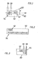
- markings 50 e.g. stick-on price labels, shown e.g. is attached to a container, a package or any article of goods and appears in an arbitrary position and orientation on a picture window.
- the image window is, for example, by the optical: .Aperture a.
- Light point scanning device for example of a video icon, determined by which the image window first line by line, is then scanned in a line-shaped scanning grid.
- the labels 50 each have a data field which contains, in at least one data track 51, contrasting characters 52 for identifying the goods provided with this label.
- the contrasting characters preferably consist of plain characters in one of the known machine-readable fonts, e.g. in the OCR-A script or the OCR-B script.
- a contrast line pattern 54 also called a position identification code PIC, is arranged in a predetermined position and orientation to the data track and has a plurality of parallel contrast lines with different spacing and / or line widths.
- the contrast line pattern is attached according to FIG. 1 in front of the data track, according to FIG. 2, below the data track, according to FIG. 3 at the end of the data track.
- the contrast line pattern 54 is designed asymmetrically perpendicular to the contrast lines in order to identify the data field with regard to the start and end of the data tracks.
- the contrast line patterns shown in FIGS. 1 and 2, hereinafter referred to as PIC patterns, have a character-free leading zone 56 and a character-free trailing zone 58.
- PIC patterns with three lines each are shown, PIC patterns with more than three lines can also be used.
- the PIC patterns - in contrast to FIGS. 1 to 3 - can also be applied in a different position and different orientation with regard to the data tracks, and two or more PIC patterns can also be applied to an identification field 50.
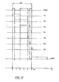
- the image window, or an image corresponding to the image window, for example on the target of a video icon, is scanned step by step with a step angle ⁇ of at least one scanning line 60 each. It is essential that, before reading the data tracks, the PIC pattern is first reliably recognized and its position and orientation relative to the scanning beam 60 is determined, since the characters contained in the data track can then be read by a subsequent raster scan in the direction of the data track.
- FIG. 4 shows the light-dark distribution of various PIC patterns containing three lines perpendicular to the line direction, all of which are constructed asymmetrically and can therefore be used according to the invention.
- FIG. 5 shows a section of the video signal which is obtained as an electrical, binary signal when a PIC pattern according to FIG. 4a is scanned, dark regions of the PIC pattern being assigned the amplitude Hi and light regions of the PIC pattern being assigned the amplitude Lo . Any light-dark fluctuations within the individual lines and distances of the PIC pattern are eliminated in the electrical signal immediately after scanning. 5 are a character-free leading zone, which corresponds to zone 56 in FIG.
- the labels 50 each have a data field that contains contrasting characters 52 in at least one data track 51 for identifying the goods provided with this label.
- the contrasting characters preferably consist of plain characters in one of the known machine-readable fonts, e.g. in the OCR-A script or the OCR-B script.
- a contrast line pattern 54 also called a position identification code PIC, is arranged in a predetermined position and orientation to the data track and has a plurality of parallel contrast lines with different spacing and / or line widths. According to FIG. 1, the contrast line pattern is applied before the data track, according to FIG. 2, below the data track, according to FIG. 3 at the end of the data track.
- the contrast line pattern 54 is designed asymmetrically perpendicular to the contrast lines in order to identify the data field with regard to the start and end of the data tracks.
- the contrast line patterns shown in FIGS. 1 and 2, hereinafter referred to as PIC patterns, have a character-free leading zone 56 and a character-free trailing zone 58.
- PIC patterns with three lines each are shown, PIC patterns with more than three lines can also be used.
- the PIC patterns - in contrast to FIGS. 1 to 3 - can also be applied in a different position and different orientation with regard to the data tracks, and two or more PIC patterns can also be applied to an identification field 50.
- the image window, or an image corresponding to the image window, for example on the target of a video icon, is scanned step by step with a step angle ⁇ of at least one scanning line 60 each. It is essential that, before reading the data tracks, the PIC pattern is first reliably recognized, and its position and orientation relative to the scanning beam 60 is determined, since the characters contained in the data track can then be read by a subsequent Easter scan in the direction of the data track .
- FIG. 4 shows the light-dark distribution of various PIC patterns containing three lines perpendicular to the line direction, all of which are constructed asymmetrically and can therefore be used according to the invention.
- FIG. 5 shows a section of the video signal which is obtained as an electrical, binary signal when a PIC pattern according to FIG. 4a is scanned, dark regions of the PIC pattern being assigned the amplitude Hi and light regions of the PIC pattern being assigned the amplitude Lo . Any light-dark fluctuations within the individual lines and distances of the PIC pattern are eliminated in the electrical signal immediately after scanning. 5 are a character-free leading zone, which corresponds to zone 56 in FIG.
- the decoding of the PIC pattern is carried out according to the delta distance method, in each of which it is checked whether successive and overlapping intervals, that is to say T 1, T 2 and T 2, T 3 and T 3, T 4, in a predetermined ratio to one another stand, which is given by the PIC pattern to be decoded. If the value of the quotient of successive, overlapping interval lengths lies within predetermined value ranges, the range widths being given by the pressure blurs and the digitization blurs, then the PIC pattern sought is most likely present.
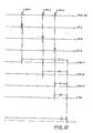
- the counting circuit contains a timing control circuit 2, to which the video signal VIDEO is fed, and which has a first gate signal from a first rising edge to a second rising edge of the video signal at a first output, and a second gate signal T 2 from a second rising edge following a second output Falling edge to a second falling edge of the video signal, at a third output a third gate signal T 3 from the second rising edge to the next, third rising edge, and at a fourth output a fourth gate signal T 4 from the second falling edge to a next, third Emits a falling edge, cf. the pulse schedule according to FIG.
- the gate signals T 1 to T 4 are fed individually to each of a counter 6 to 12 in the gate input G 1 to G 4.
- Each counter 6 to 12 receives 4 clock pulses from a clock generator 14 at its counter input CT 1 to CT the counters 6 to 12 are counted as long as the gate signal T 1 to T 4 is present.
- the counter reading that can be output at the outputs TC 1 to TC 4 of the counters 6 to 12 then represents a measure of the length of the gate signals T 1 to T 4.
- a trigger signal E 2 is generated in the timing control circuit 2 by the rising edge of the gate signal T 2
- a trigger signal E 3 is generated by the falling edge of the gate signal T 3
- a trigger signal E 4 is generated by the falling edge of the gate signal T 4 and is output at separate outputs.
- a signal PWAIT is also generated by the trigger signal E 4, the length of which corresponds to the character-free trailing zone after the end of the gate signal T 4 and is emitted at a separate output.
- the counter circuit also contains a reset circuit 4 which receives the video signal VIDEO and, at a separate input, an external reset signal RESET IN at the beginning of each scan line.
- the reset circuit 4 sends a reset signal RESET to the reset input RS 1 to RS 4 of the counters 6 to 12 and to the timing circuit 2 and resets the counters 6 to 12 and the timing circuit 2 to the active initial state if the video signal has a character-free section - Amplitude Lo - contains, which is greater than the maximum scanning distance between the lines of the PIC pattern, this maximum scanning distance being given by the maximum distance within the PIC pattern, multiplied by the maximum permissible scanning angle.
- the counter circuit also contains an overflow detection 40, which receives an overflow signal from the overflow output OV 1 to OV 4 of the counters 6 to 12 and then emits a reset signal OV RESET and then the decoding device reset to a new ready state.
- an overflow detection 40 which receives an overflow signal from the overflow output OV 1 to OV 4 of the counters 6 to 12 and then emits a reset signal OV RESET and then the decoding device reset to a new ready state.
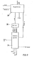
- Fig. 7 shows an embodiment of the comparison table of the decoding device.
- the comparison table contains a read-only memory PROM, 28.
- the PROM 28 is organized in such a way that the count TC 1 of the counter addresses 6 individual lines of the memory matrix,
- the counter readings TC 1 and TC 2 are applied to the PROM 28 via the gate circuit 16, 18 after the counter reading TC 2 has been counted by the trigger signal E 2.
- An expectation field is specified within the first memory matrix, which includes those memory locations in which the quotient of the row address and column address lies within a predetermined value range. This range of values corresponds in the quotient from the first interval length to the second interval length of the PIC pattern used. If a memory location within the expected field is addressed by the counts TC 1 and TC 2, a comparison signal with a first amplitude, e.g. Hi, which signals that information was scanned that corresponds to part of the PIC pattern used.
- the counter reading TC 2 of the second counter 8 addresses the rows of a second memory matrix
- the counter reading TC 3 of the third counter 10 addresses the columns of the second memory matrix. Addressing takes place after the counter reading TC 3 has been counted and the counter readings TC 2 and TC 3 through the trigger signal E 3 the gate circuit 20, 22 are supplied to the PROM 28.
- an expectation field is also specified, which includes those memory locations whose quotient of row 7 address and column address lies within a predetermined range which is equal to the value range of the quotient of the intervals of the PIC pattern corresponding to the gate signals T 2 and T 3 .
- a comparison signal with the first amplitude for example the amplitude Hi, is emitted.
- a comparison signal with a second amplitude Lo is emitted.
- the counter readings TC 3 of the third counter 10 are compared in the same way by addressing rows and columns of a third memory matrix, which also contains an expectation field, with a comparison signal having the first amplitude Hi when addressing a memory location within the expectation field is delivered.
- the third memory matrix is addressed after the counter reading TC 4 of the fourth counter 12 has been counted and the trigger signal E 4 outputs the counter readings TC 3 and TC 4 to the PROM 28 through the gate circuit 24 and .26.
- the gate circuits 16 to 26 consist of AND gates.
- the comparison signals LPIC 1, LPIC 2 and LPIC 3 are read out by the readout signals EL 2, EL 3 and EL 4, which are obtained by delaying the trigger signals E 2, E 3, and E 4 in the delay circuit 30, compare the pulse schedule according to Fig. 12.
- the reading may only take place after the addressing of the first, second and third memory matrix has settled.
- the first memory matrix can be implemented by a first read-only memory, PROM 1, the second memory matrix by a second read-only memory, PROM 2, and the third memory matrix by a third read-only memory PROM 3, since then advantageously three individual read-only memories much smaller storage capacity can be used.
- the PROM 28 is followed by a changeover switch 32 which selectively reads the comparison signals LPIC 1, LPIC 2 and LPIC3 from the relevant bits of the memory locations and at its output the evaluation signal MUX PIC formed from the sequential comparison signals LPIC 1 and LPIC 2 and LPIC3 transfers to the evaluation circuit.
- a buffer 34 receives the evaluation signal MÜX PIC and stores the comparison signal LPIC 1 - which indicates that the value TC 1 / TC 2 lies within a predetermined range - as well as the comparison signal LPIC 2 and the comparison signal LPIC 3.
- the storage takes place by entering the read-out signals EL 2, EL 3 and EL 4, which occurs essentially simultaneously with the comparison signals LPIC 1, LPIC 2 and LPIC3, compare the pulse diagram according to FIG. 12.
- these memory signals are output to an AND gate 36 which emits an output signal LPIC when all the memory signals LPIC 1 1 etc.
- the output signal LPIC is supplied to an output circuit 38 which receives the video signal VIDEO and from the control circuit 2 the wait signal PWAIT.
- the output circuit 38 emits a detection signal PIC OUT if the video signal VIDEO remains at the amplitude Lo during the application of the waiting signal PWAIT, which characterizes a character-free background. This ensures that the decoded line pattern is followed by a character-free tracking zone that is equal to the tracking zone 58 of the PIC pattern.
- the output circuit 38 is reset by the external reset signal RESET IN, which then emits a reset signal RESETA to the intermediate memory 34 and also resets it for renewed operation.
- the buffer is also reset by the overflow reset signal OV RESET when a counter 6 to .12 signals an overflow.
- Fig. 10 shows a schematic representation of how the Comparison table, for example the partial comparison table of PROM 1 for comparing the quotient TC 1 / TC 2.
- the table is shown as a memory matrix, the rows of the table are continuously designated with binary addresses. The columns of the table are also designated consecutively with binary addresses, a 5-bit representation being selected in accordance with a preferred embodiment of the decoding device according to the invention. All memory locations with a certain value of the quotient from row address to column address lie on a line, the so-called expectation line, around which the expectation field lies, within which all memory locations are located whose address quotients are within a predetermined value range.
- the counter readings TC 1 to TC 4 are also given as 5-bit words. The counter reading TC 1 addresses the rows of the table, the counter reading TC 2 addresses the columns of the table.
- Fig. 13 is a circuit diagram showing another embodiment of the Comparison Table according to Fig. 8.
- the comparison table is composed of a first read-only memory PROM 1, yorattention addressed by the measured first counting interval TC 1, and the columns by the second measured counting interval TC 2 we re whose rows There is also a second read-only memory PROM 2, the rows of which are addressed by the measured second counting interval TC 2, and the columns of which are addressed by the third counting interval TC 3. Finally, a third read-only memory PROM 3, meanwhile rows by the third counting interval TC 3, and its Columns are addressed by the counted fourth count interval TC 4.
- Each read-only memory PROM 1, PROM 2, ... thus contains a two-dimensional, row and column-organized storage matrix, which in each case realizes a comparison table for two successive, measured, ie counted counting intervals of the contrast line pattern.
- the read-only memories PROM 1, PROM 2, ... are followed by a gate circuit 28, which is n parallel Contains AND gates 29.
- the AND gates 29 each have as many input connections that correspond to the number of PROM 1, PROM 2,...
- an interface 29a is coupled to each read-only memory output, which outputs the data word read out at the output bit-parallel and the interface therefore has n outputs, which appears at the first output first bit, at the second output the second bit, at the third output the third bit etc ... of the read n-bit data word.
- AND gates 29 are coupled to the interfaces 29a in such a way that the mth AND gate receives the mth bit of the data words read from the various read-only memories at its various input connections as input signals.
- Each AND gate outputs an LPIC output signal if all of its input signals have the value "hi", i.e. if the mth bit of all read-only memories has the value "hi” and it is ascertained that the contrast line pattern PIC that has just been read lies in the mth recognition field and was recognized without interference.
- a first AND gate 29 emits a pulse after a search (first method step)
- a first contrast line pattern was recognized. If, on the other hand, the mth AND gate emits a pulse, the mth contrast line pattern was recognized.
- AND gates 29 is followed by a selection circuit (not shown) which can be set externally to one or a group of the unread m-PIC patterns and which only outputs the output when the relevant PIC pattern or patterns occur.
Landscapes
- Engineering & Computer Science (AREA)
- Physics & Mathematics (AREA)
- Computer Vision & Pattern Recognition (AREA)
- General Physics & Mathematics (AREA)
- Theoretical Computer Science (AREA)
- Electromagnetism (AREA)
- Health & Medical Sciences (AREA)
- General Health & Medical Sciences (AREA)
- Toxicology (AREA)
- Artificial Intelligence (AREA)
- Multimedia (AREA)
- Character Input (AREA)
- Character Discrimination (AREA)
- Image Analysis (AREA)
- Signal Processing Not Specific To The Method Of Recording And Reproducing (AREA)
- Package Frames And Binding Bands (AREA)
- Management, Administration, Business Operations System, And Electronic Commerce (AREA)
- Financial Or Insurance-Related Operations Such As Payment And Settlement (AREA)
- Television Signal Processing For Recording (AREA)
- Sorting Of Articles (AREA)
- Image Processing (AREA)
- Developing Agents For Electrophotography (AREA)
- Credit Cards Or The Like (AREA)
- Eye Examination Apparatus (AREA)
- Control Of Vending Devices And Auxiliary Devices For Vending Devices (AREA)
- Vending Machines For Individual Products (AREA)
- Automatic Analysis And Handling Materials Therefor (AREA)
Priority Applications (1)
| Application Number | Priority Date | Filing Date | Title |
|---|---|---|---|
| AT81107881T ATE9742T1 (de) | 1980-10-17 | 1981-10-03 | Verfahren und vorrichtung zum erkennen von kontrastlinienmustern an gegenstaenden. |
Applications Claiming Priority (2)
| Application Number | Priority Date | Filing Date | Title |
|---|---|---|---|
| DE3039191 | 1980-10-17 | ||
| DE3039191A DE3039191C2 (de) | 1980-10-17 | 1980-10-17 | Verfahren zum Identifizieren von Gegenständen sowie Vorrichtung zum Durchführen des Verfahrens |
Publications (2)
| Publication Number | Publication Date |
|---|---|
| EP0050252A1 true EP0050252A1 (fr) | 1982-04-28 |
| EP0050252B1 EP0050252B1 (fr) | 1984-10-03 |
Family
ID=6114564
Family Applications (1)
| Application Number | Title | Priority Date | Filing Date |
|---|---|---|---|
| EP81107881A Expired EP0050252B1 (fr) | 1980-10-17 | 1981-10-03 | Méthode et dispositif pour l'identification d'un patron de lignes de contraste sur des objets |
Country Status (8)
| Country | Link |
|---|---|
| EP (1) | EP0050252B1 (fr) |
| JP (1) | JPS57136281A (fr) |
| AT (1) | ATE9742T1 (fr) |
| AU (1) | AU7653681A (fr) |
| CA (1) | CA1175571A (fr) |
| DE (2) | DE3039191C2 (fr) |
| FI (1) | FI813167A7 (fr) |
| NO (1) | NO813504L (fr) |
Cited By (3)
| Publication number | Priority date | Publication date | Assignee | Title |
|---|---|---|---|---|
| EP0050252B1 (fr) * | 1980-10-17 | 1984-10-03 | Scantron GmbH & Co. Elektronische Lesegeräte KG | Méthode et dispositif pour l'identification d'un patron de lignes de contraste sur des objets |
| GB2157873A (en) * | 1984-04-18 | 1985-10-30 | Oberon International Limited | Character recognition |
| CN115083046A (zh) * | 2022-06-28 | 2022-09-20 | 维沃移动通信有限公司 | 解密方法、解密信息创建方法及解密装置 |
Families Citing this family (2)
| Publication number | Priority date | Publication date | Assignee | Title |
|---|---|---|---|---|
| NL8403323A (nl) * | 1984-11-02 | 1986-06-02 | Philips Nv | Leesinrichting voor staafkodes. |
| JPS6418187A (en) * | 1987-07-13 | 1989-01-20 | Sharp Kk | Pseudo font input system |
Citations (5)
| Publication number | Priority date | Publication date | Assignee | Title |
|---|---|---|---|---|
| US3784792A (en) * | 1972-03-29 | 1974-01-08 | Monarch Marking Systems Inc | Coded record and methods of and apparatus for encoding and decoding records |
| DE2338561A1 (de) * | 1972-08-30 | 1974-05-09 | Scanner | Verfahren und vorrichtung zum identifizieren von objekten |
| US3854036A (en) * | 1974-02-27 | 1974-12-10 | Singer Co | Tag reader to digital processor interface circuit |
| DE2457259A1 (de) * | 1973-12-05 | 1975-06-12 | Data General Corp | Verfahren zum lesen eines codes auf einem aufzeichnungsmedium |
| EP0017950A1 (fr) * | 1979-04-19 | 1980-10-29 | Scantron GmbH & Co. Elektronische Lesegeräte KG | Procédé et dispositif pour l'identification d'objets |
Family Cites Families (1)
| Publication number | Priority date | Publication date | Assignee | Title |
|---|---|---|---|---|
| DE3039191C2 (de) * | 1980-10-17 | 1984-10-04 | Scantron GmbH & Co Elektronische Lesegeräte KG, 6000 Frankfurt | Verfahren zum Identifizieren von Gegenständen sowie Vorrichtung zum Durchführen des Verfahrens |
-
1980
- 1980-10-17 DE DE3039191A patent/DE3039191C2/de not_active Expired
-
1981
- 1981-10-03 DE DE8181107881T patent/DE3166498D1/de not_active Expired
- 1981-10-03 EP EP81107881A patent/EP0050252B1/fr not_active Expired
- 1981-10-03 AT AT81107881T patent/ATE9742T1/de not_active IP Right Cessation
- 1981-10-09 JP JP56161913A patent/JPS57136281A/ja active Pending
- 1981-10-13 FI FI813167A patent/FI813167A7/fi not_active Application Discontinuation
- 1981-10-16 CA CA000388105A patent/CA1175571A/fr not_active Expired
- 1981-10-16 NO NO813504A patent/NO813504L/no unknown
- 1981-10-16 AU AU76536/81A patent/AU7653681A/en not_active Abandoned
Patent Citations (5)
| Publication number | Priority date | Publication date | Assignee | Title |
|---|---|---|---|---|
| US3784792A (en) * | 1972-03-29 | 1974-01-08 | Monarch Marking Systems Inc | Coded record and methods of and apparatus for encoding and decoding records |
| DE2338561A1 (de) * | 1972-08-30 | 1974-05-09 | Scanner | Verfahren und vorrichtung zum identifizieren von objekten |
| DE2457259A1 (de) * | 1973-12-05 | 1975-06-12 | Data General Corp | Verfahren zum lesen eines codes auf einem aufzeichnungsmedium |
| US3854036A (en) * | 1974-02-27 | 1974-12-10 | Singer Co | Tag reader to digital processor interface circuit |
| EP0017950A1 (fr) * | 1979-04-19 | 1980-10-29 | Scantron GmbH & Co. Elektronische Lesegeräte KG | Procédé et dispositif pour l'identification d'objets |
Non-Patent Citations (1)
| Title |
|---|
| Elektronik, Band 22, Heft 11, November 1973, seiten 395-398 Munchen, DE. K.R. KIMMEL et al.: "Rationelle Multiplikation und Devision mit Festwertspeichern" * seite 397 * * |
Cited By (3)
| Publication number | Priority date | Publication date | Assignee | Title |
|---|---|---|---|---|
| EP0050252B1 (fr) * | 1980-10-17 | 1984-10-03 | Scantron GmbH & Co. Elektronische Lesegeräte KG | Méthode et dispositif pour l'identification d'un patron de lignes de contraste sur des objets |
| GB2157873A (en) * | 1984-04-18 | 1985-10-30 | Oberon International Limited | Character recognition |
| CN115083046A (zh) * | 2022-06-28 | 2022-09-20 | 维沃移动通信有限公司 | 解密方法、解密信息创建方法及解密装置 |
Also Published As
| Publication number | Publication date |
|---|---|
| DE3166498D1 (en) | 1984-11-08 |
| ATE9742T1 (de) | 1984-10-15 |
| DE3039191C2 (de) | 1984-10-04 |
| CA1175571A (fr) | 1984-10-02 |
| AU7653681A (en) | 1982-04-22 |
| NO813504L (no) | 1982-04-19 |
| EP0050252B1 (fr) | 1984-10-03 |
| DE3039191A1 (de) | 1982-05-06 |
| FI813167L (fi) | 1982-04-18 |
| FI813167A7 (fi) | 1982-04-18 |
| JPS57136281A (en) | 1982-08-23 |
Similar Documents
| Publication | Publication Date | Title |
|---|---|---|
| DE4000603C2 (de) | Verfahren und Vorrichtung zur Zwischenspeicherung von Gegenständen, wie Briefen o.ä. in einem Lesesystem | |
| EP0027594B1 (fr) | Procédé et dispositif pour l'identification d'objets | |
| DE19646522C2 (de) | Verfahren und Vorrichtung zur Erkennung von Verteilinformationen auf Sendungen | |
| EP0038027B1 (fr) | Procédé et dispositif pour la lecturs et le décodage des caractères en clair sur des objets | |
| DD209420A5 (de) | Verteileranlage fuer bewegte stueckgueter | |
| DE2354723A1 (de) | Verfahren und vorrichtung zum identifizieren von objekten | |
| DE2338561A1 (de) | Verfahren und vorrichtung zum identifizieren von objekten | |
| DE1774490A1 (de) | Verfahren zum selbsttaetigen Sortieren oder Registrieren von Gegenstaenden sowie Vorrichtung zur Ausfuehrung des Verfahrens | |
| DE2321701A1 (de) | Kartenleser mit mehreren lesekanaelen | |
| DE2900181C2 (fr) | ||
| DE3621661A1 (de) | Verfahren zur erkennung eines ziels | |
| EP0050252A1 (fr) | Méthode et dispositif pour l'identification d'un patron de lignes de contraste sur des objets | |
| DE1774690A1 (de) | Verfahren und Vorrichtung zum Aufdrucken von Codierfarben sowie zum Abfragen der Informationen | |
| EP0017950B1 (fr) | Procédé et dispositif pour l'identification d'objets | |
| DE2302442A1 (de) | Verfahren und vorrichtung zum lesen von ziffern | |
| DE2826175A1 (de) | Verfahren und vorrichtung zur umwandlung von strichkodesignalen | |
| DE10161302B4 (de) | Verfahren zum Unterscheiden von mindestens zwei in einem Wirkfeld einer Lesevorrichtung befindlichen RFID-Tags und RFID-Tag | |
| DE2942747C2 (de) | Verfahren zum Identifizieren von Gegenständen sowie Vorrichtung zur Durchführung des Verfahrens | |
| DE3014350A1 (de) | Verfahren und vorrichtung zum indentifizieren von gegenstaenden | |
| AT214680B (de) | Kennzeichnung von Sortiergut | |
| DE2264170C3 (de) | Anordnung zum mehrfach seriellen Lesen der Zeichen eines binären optischen Coderasters | |
| DE2360012A1 (de) | Einrichtung zur elektrooptischen zeichenerkennung | |
| DE3303647A1 (de) | Verfahren zur chaotischen verfilmung von belegen und vorrichtung zur durchfuehrung desselben | |
| DE1907967B2 (de) | Vorrichtung zum punktweisen Darstellen graphischer Zeichen auf dem Schirm einer Abtasteinrichtung | |
| DE2210204A1 (de) | Optisches Kartenlesegerät |
Legal Events
| Date | Code | Title | Description |
|---|---|---|---|
| PUAI | Public reference made under article 153(3) epc to a published international application that has entered the european phase |
Free format text: ORIGINAL CODE: 0009012 |
|
| AK | Designated contracting states |
Designated state(s): AT BE CH DE FR GB IT LU NL SE |
|
| 17P | Request for examination filed |
Effective date: 19821021 |
|
| GRAA | (expected) grant |
Free format text: ORIGINAL CODE: 0009210 |
|
| AK | Designated contracting states |
Designated state(s): AT BE CH DE FR GB IT LI LU NL SE |
|
| PG25 | Lapsed in a contracting state [announced via postgrant information from national office to epo] |
Ref country code: SE Effective date: 19841003 Ref country code: NL Effective date: 19841003 Ref country code: IT Free format text: LAPSE BECAUSE OF FAILURE TO SUBMIT A TRANSLATION OF THE DESCRIPTION OR TO PAY THE FEE WITHIN THE PRESCRIBED TIME-LIMIT;WARNING: LAPSES OF ITALIAN PATENTS WITH EFFECTIVE DATE BEFORE 2007 MAY HAVE OCCURRED AT ANY TIME BEFORE 2007. THE CORRECT EFFECTIVE DATE MAY BE DIFFERENT FROM THE ONE RECORDED. Effective date: 19841003 |
|
| REF | Corresponds to: |
Ref document number: 9742 Country of ref document: AT Date of ref document: 19841015 Kind code of ref document: T |
|
| PG25 | Lapsed in a contracting state [announced via postgrant information from national office to epo] |
Ref country code: LU Free format text: LAPSE BECAUSE OF NON-PAYMENT OF DUE FEES Effective date: 19841031 |
|
| REF | Corresponds to: |
Ref document number: 3166498 Country of ref document: DE Date of ref document: 19841108 |
|
| ET | Fr: translation filed | ||
| PGFP | Annual fee paid to national office [announced via postgrant information from national office to epo] |
Ref country code: DE Payment date: 19850301 Year of fee payment: 4 |
|
| NLV1 | Nl: lapsed or annulled due to failure to fulfill the requirements of art. 29p and 29m of the patents act | ||
| PLBE | No opposition filed within time limit |
Free format text: ORIGINAL CODE: 0009261 |
|
| STAA | Information on the status of an ep patent application or granted ep patent |
Free format text: STATUS: NO OPPOSITION FILED WITHIN TIME LIMIT |
|
| 26N | No opposition filed | ||
| PGFP | Annual fee paid to national office [announced via postgrant information from national office to epo] |
Ref country code: AT Payment date: 19861222 Year of fee payment: 6 |
|
| PG25 | Lapsed in a contracting state [announced via postgrant information from national office to epo] |
Ref country code: AT Effective date: 19871003 |
|
| PG25 | Lapsed in a contracting state [announced via postgrant information from national office to epo] |
Ref country code: LI Effective date: 19871031 Ref country code: CH Effective date: 19871031 Ref country code: BE Effective date: 19871031 |
|
| BERE | Be: lapsed |
Owner name: SCANTRON G.M.B.H. & CO. ELEKTRONISCHE LESEGERATE Effective date: 19871031 |
|
| REG | Reference to a national code |
Ref country code: CH Ref legal event code: PL |
|
| PG25 | Lapsed in a contracting state [announced via postgrant information from national office to epo] |
Ref country code: GB Effective date: 19891003 |
|
| GBPC | Gb: european patent ceased through non-payment of renewal fee | ||
| PG25 | Lapsed in a contracting state [announced via postgrant information from national office to epo] |
Ref country code: FR Effective date: 19900629 |
|
| PG25 | Lapsed in a contracting state [announced via postgrant information from national office to epo] |
Ref country code: DE Effective date: 19900703 |
|
| REG | Reference to a national code |
Ref country code: FR Ref legal event code: ST |