EP0050274A2 - Dispositif de levage de véhicule utilisé, en particulier dans des garages - Google Patents
Dispositif de levage de véhicule utilisé, en particulier dans des garages Download PDFInfo
- Publication number
- EP0050274A2 EP0050274A2 EP81108064A EP81108064A EP0050274A2 EP 0050274 A2 EP0050274 A2 EP 0050274A2 EP 81108064 A EP81108064 A EP 81108064A EP 81108064 A EP81108064 A EP 81108064A EP 0050274 A2 EP0050274 A2 EP 0050274A2
- Authority
- EP
- European Patent Office
- Prior art keywords
- ramps
- floor
- conduit
- ramp
- cylinder
- Prior art date
- Legal status (The legal status is an assumption and is not a legal conclusion. Google has not performed a legal analysis and makes no representation as to the accuracy of the status listed.)
- Withdrawn
Links
- 239000002184 metal Substances 0.000 claims description 8
- 230000009471 action Effects 0.000 claims description 6
- 230000000284 resting effect Effects 0.000 claims description 6
- 238000004891 communication Methods 0.000 claims description 4
- 238000007789 sealing Methods 0.000 claims description 4
- 238000004873 anchoring Methods 0.000 claims description 2
- 230000015572 biosynthetic process Effects 0.000 claims description 2
- 238000005755 formation reaction Methods 0.000 claims description 2
- 230000002040 relaxant effect Effects 0.000 claims description 2
- 238000005096 rolling process Methods 0.000 claims 2
- 230000005484 gravity Effects 0.000 claims 1
- 238000009434 installation Methods 0.000 description 6
- 230000004048 modification Effects 0.000 description 6
- 238000012986 modification Methods 0.000 description 6
- 238000010276 construction Methods 0.000 description 4
- 239000012530 fluid Substances 0.000 description 4
- 238000010586 diagram Methods 0.000 description 2
- 230000000694 effects Effects 0.000 description 2
- 206010003830 Automatism Diseases 0.000 description 1
- 230000003213 activating effect Effects 0.000 description 1
- 230000008859 change Effects 0.000 description 1
- 230000009194 climbing Effects 0.000 description 1
- LYKJEJVAXSGWAJ-UHFFFAOYSA-N compactone Natural products CC1(C)CCCC2(C)C1CC(=O)C3(O)CC(C)(CCC23)C=C LYKJEJVAXSGWAJ-UHFFFAOYSA-N 0.000 description 1
- 230000000881 depressing effect Effects 0.000 description 1
- 238000013461 design Methods 0.000 description 1
- 238000007599 discharging Methods 0.000 description 1
- 230000002349 favourable effect Effects 0.000 description 1
- 238000003780 insertion Methods 0.000 description 1
- 230000037431 insertion Effects 0.000 description 1
- 230000002452 interceptive effect Effects 0.000 description 1
- 239000000463 material Substances 0.000 description 1
- 238000000034 method Methods 0.000 description 1
- 229920003023 plastic Polymers 0.000 description 1
- 239000004033 plastic Substances 0.000 description 1
- 230000009467 reduction Effects 0.000 description 1
- 230000000717 retained effect Effects 0.000 description 1
- 238000012360 testing method Methods 0.000 description 1
Images




Classifications
-
- B—PERFORMING OPERATIONS; TRANSPORTING
- B66—HOISTING; LIFTING; HAULING
- B66F—HOISTING, LIFTING, HAULING OR PUSHING, NOT OTHERWISE PROVIDED FOR, e.g. DEVICES WHICH APPLY A LIFTING OR PUSHING FORCE DIRECTLY TO THE SURFACE OF A LOAD
- B66F7/00—Lifting frames, e.g. for lifting vehicles; Platform lifts
- B66F7/22—Lifting frames, e.g. for lifting vehicles; Platform lifts with tiltable platforms
-
- B—PERFORMING OPERATIONS; TRANSPORTING
- B66—HOISTING; LIFTING; HAULING
- B66F—HOISTING, LIFTING, HAULING OR PUSHING, NOT OTHERWISE PROVIDED FOR, e.g. DEVICES WHICH APPLY A LIFTING OR PUSHING FORCE DIRECTLY TO THE SURFACE OF A LOAD
- B66F7/00—Lifting frames, e.g. for lifting vehicles; Platform lifts
- B66F7/24—Lifting frames, e.g. for lifting vehicles; Platform lifts for raising or lowering vehicles by their own power
- B66F7/243—Ramps
-
- E—FIXED CONSTRUCTIONS
- E04—BUILDING
- E04H—BUILDINGS OR LIKE STRUCTURES FOR PARTICULAR PURPOSES; SWIMMING OR SPLASH BATHS OR POOLS; MASTS; FENCING; TENTS OR CANOPIES, IN GENERAL
- E04H6/00—Buildings for parking cars, rolling-stock, aircraft, vessels or like vehicles, e.g. garages
- E04H6/02—Small garages, e.g. for one or two cars
- E04H6/06—Small garages, e.g. for one or two cars with means for shifting or lifting vehicles
- E04H6/065—Small garages, e.g. for one or two cars with means for shifting or lifting vehicles using tiltable floors or ramps
Definitions
- This invention relates to a vehicle hoisting device, particularly for use in garages.
- apparatus In an attempt to provide full exploitation of the available space, apparatus have been proposed which had tiltable ramps arranged to receive a car thereon while resting on the floor with one end, to then perform a rotational movement about a pivot pin causing the raising of the car and leaving a space portion available for occupation by a second car.
- the task of the present invention is to provide a vehicle hoisting device,particularly for use in garages, with optimized constructional and functional characteristics, owing to the provision of floor engaging means of minimized bulk and suitable for use in all types of garages and also for installation on either finished floors or floors still under construction, as well as of automatic valving means effective to simplify the hydraulic system and cooperate with such safety means, which ensure per se the utmost degree of reliability.
- a vehicle hoisting device particularly for use in garages, according to the invention, comprising two ramps rigidly connected and intended to support at least one of the wheel pairs carried on one axle of a vehicle and having at least one single-acting hydraulic cylinder operative to cause their rotation up from the position with the free end resting on the floor, characterized in that it comprises floor engaging means having structural formations for pivotally supporting said ramps substantially near one end thereof and automatic distributing valve means located in the hydraulic system and cooperating with safety means against the unintentional lowering of the ramps.
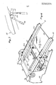
- the device floor engaging means comprise two side members 1 and 2 interconnected by removably ⁇ attached crosspieces the rear one whereof is indicated at 3 and the front one at 4; the latter can be locked in an adjustable position at the floor such as to constitute a detent element for the front wheels of the vehicle intended to arrange itself at the space portion under the raised ramps.
- the ramps 5 and 6 on which the vehicle is to climb which must be raised up are rigidly connected by the crosspiece 7 and have at the end at the pivot area the concave portions 5a and 6a which are shaped with a radius substantially coinciding with the maximum one to be found on vehicle wheels, and hingedly connected to the side members 1 and 2 through pivot pins such as 5b for the ramp 5, located at positions substantially coinciding with the center of curvature of said concave portions.
- the two ramps are of identical configuration,and it may be seen that the ramp 5 comprises a first segment 5c including the concave region 5a at its end, and a second segment 5d removably attachable to the first at a longitudinally adjustable position, thereby the device can be ideally adapted to fit the type of vehicle and size of the garage; for the same purpose, the concave metal sheet 5e removably attachable to the concave region 5a is provided.
- the vehicle to be raised will thus be driven up the ramps 5 and 6 positioned with their ends resting onto the floor, until one pair of wheels, preferably the rear ones, are brought to seat in the concave portions 5a and 6a, thereafter the ramps will be rotated upwards until the final desired position is reached as determined by a limit switch, through the actuation of the hydraulic cylinder 8 of the single-acting type which is pivoted to the fixed crosspiece 3 and with the piston active on the crosspiece 7, under control from a hydraulic unit, not shown, comprising an electric pump, an oil reservoir, a pressure accumulator, and automatic valving means, as will be explained hereinafter with reference to Figures 8 and 9.
- Said cylinder 8 is provided, in the space portion above the top face of the piston, with a sufficient amount of oil to stop the movement thereof in the event of failure of the limit switch.
- the floor engaging means comprising the side members 1 and 2 lends themselves for installation on finished floors; where the garage is still under construction, said means, shown in Figures 3 and 4, would comprise the frame 10 having,at the ends, plates 11 and 12 and, at the middle, a plate 13, all of which extend coplanarly, which is intended for insertion into the garage floor with the top surfaces of said plates flush with the floor surface, as shown in Figure 3, and secured therein by means of anchoring means such as the lag bolts indicated at 14 incorporated to it.
- the modification of the device shown in Figure 5 may be adopted; there is shown in the latter, as indicated at 21, one of the device ramps pivoted at 22 to the upright 23, which may be attached to a frame embedded into the floor, not shown in the figure; the height above the floor of the pivot pin 22 is such that, in the fully lowered position, the ramp takes a substantially horizontal lay, to thus make the climbing of the vehicle thereon most easily carried out , while in the fully raised position even the topmost parts of the raised vehicle 24 reach a relatively low height level, without prejudice for the comfortable accomodation of a car 25.
- the hydraulic lift cylinder which is pivoted at 27 to the bottom of a pit 28 formed in the floor and provided with the safety device.
- the ramp 1 and of course the other ramp extending parallel thereto, has a bottom shaped cradle-like at a region 21a for receiving the vehicle wheel therein.
- Figure 6 shows another embodiment of the device; indicated at 29 therein is the fixed floor engaging structure which carries the tube 30 constituting the pivot pin for the two ramps, generally indicated at 31 and 32, intended to receive the wheels of the vehicle to be raised in the manner to be explained hereinafter.
- the ramps 31 and 32 identically comprise three segments each, thereby the ramp 31 is composed of a first segment, indicated at 31a, rigidly attached to the tube 30, a second segment, indicated at 31b and removably attached to the first at a transversely adjustable position, and a third segment, indicated at 31c, which is removably attached to the second at a longitudinally adjustable position.
- the floor engaging structure 29 comprises the concave portion 33 at the area directly contiguous to the pivot 30, adapted to provide support for one of the wheel pairs carried on one axle of a vehicle, said support being made more dependable by the provision of the arcuate metal sheet portions 34 and 35 removably attached by means of bolts to said portion 33 at the ramps 31 and 32.
- the ramps 31 and 32 are raised from their position with the free end resting on the floor, after a car has been driven up the ramps until one wheel pair engage the concave portion 33 and the other pair reach an area of the ramps which will depend on the length of said car, by the hydraulic cylinders 36 and 37 pivoted to the crosspiece 38 of the structure 29, the actuating circuit whereof comprises, additionally to conventional safety arrangements not shown in the figure and to an optional pressure accumulator, a pump operated manually through the lever 39, the oil reservoir for the system comprising the tube 30.
- a plastics sheet stretched between the ramps is indicated at 40.
- the assembly comprising the ramps 31 and 32 is equipped with a safety device against the unwanted lowering or descent of the ramps which constitutes a modification with respect to the one exemplarly shown in Figures 1,3 and 5, and will be described with reference to Figure 10; said device comprises the two struts indicated at 41 and 42 which are pivoted to the structure 29 at the bottom thereof, their-top ends being held by the action of springs such as 43 for the strut 41 in constant contact with the bottom side of the ramps during the upward movement thereof, until they contact, upon reaching the position of desired height shown in Figure 7, a tooth such as 44 for the strut 41, so configured as to inhibit that undesired movement of the ramps.
- the safety device further comprises the small shaft 45 which is operated manually through the handle 46 and has two crank levers 47 and 48 adapted to urge the struts with their ends toward the front region of the ramps after said ends have been released from the tooth such as 44 following a slight upward movement of the ramps, thus allowing the ramps to subsequently move down when the vehicle is to be lowered to the floor.
- valve the body whereof comprises the conduit 50 which is connected with the end 50a to the delivery pipe 51 of the pump 52, and with the other end terminates in the connector 53 to the pipe 54 which constitutes the connection to the single-acting hydraulic cylinder 55.
- the device checking the backflow to the pump which comprises the ball 56 biased by the spring 57 against its seat.
- the numeral 58 designates then a second conduit which is connected with its end 58a to the discharge pipe 59 leading to the oil reservoir 60 and opens at the other end into the portion of the conduit 50 which is included between the connector 53 and check device.
- the sliding cut-off member comprising the ball 61, adapted to contact the seat specially formed on the conduit 58, and the slider 62, with sealing rings 62a and 62b, in communication on the bottom side or face 62c, of larger surface area than the sealing seat of the ball 61 on the conduit 58, to the portion of the conduit 50 which is included between the flow checking device and the end 50a;
- the slider 62 is formed with the lug 62d adapted to contact,at the lower stroke limit, the plug 63 which plugs the sliding movement seat of the slider 62, without interfering with the flow of oil through the conduit 50.
- the cut-off member ensures a perfectly tight seal even in the presence of small misalignments between the conduit 58 and sliding movement seat of the slider 62.
- the manual cut-off device useful during the operations of adjustment of the stroke length of the piston of the cylinder 55, that is whenever it is desired to leave out the automatism, comprising the screw formed by the head 64a and stem 64b and provided with the seal rings 64c and 64d.
- the valve operates as follows: with the pump 52 in operation, the oil enters the conduit 50 from the inlet 50a, overcomes the action of the spring 57 as suitably calibrated, and then, while keeping the ball 56 off its seat, flows to the connector 53 and hence into the cylinder 55; the oil pressure acting on the side or face 62c of the slider 62, in communication with the conduit 50, generates an upwardly directed force which is greater than that generated by that same pressure downwardly onto the ball 61, in communication with the conduit 58, thanks to the favorable surface area ratio of the surfaces whereto said pressure is being applied, and consequently the ball 61 remains in its position against its seat to cut off the oil flow and prevent the oil from flowing to the discharge: this situation is depicted in Figure 9.
- Designated with the numeral 72 is then a movable plate included between the fixed plates 65 and 66, which can rotate about the axis of the cylinder 67 between two limit positions, at the first whereof, shown in the figure and defined by the limit switch 72a with which it is provided contacting a surface of the plate 65, the two bores formed therein line up or register with the bores of the plates 65 and 66,whereas in the second thereof, defined by the limit switch 72b contacting another surface of the plate 65, said bores are out of alignment with the bores of the plates 65 and 66.
- the rotation of the plate 72 occurs in either directions thanks to the opposing actions of two members, the first of which comprises the spring 73, in constant tension, connected with its ends respectively to the plate 72 and fixed plate 65 such as to produce a rotation of the plate 72 toward the position of bore misalignment, and the second of which s adapted to produce rotation in the opposite direction, comprises the spring 74, more powerful than the spring 73, connected with one end to the string 75 attached at 76 to the plate 72 and connected with the other end to the lever 77, of the type of those fitted with a rack which are used for actuating the parking brake of passenger cars, which may be locked in different positions by grasping the handle 77a and depressing the button 77b; with the lever in its limit position shown in full lines, the spring 74 is relaxed, and is put under tension by moving the lever to the limit position indicated at 77' and shown in dotted lines.
- the numeral 78 designates the plug for introducing oil from above the piston into the cylinder 67 and having, as mentioned above; the function of a stroke limiter.
- the rod 70 shortly continues to move out until, with the ends 68c and 69c of the columns still included within the bores provided in the plate 66, it meets its stroke limit, not shown, which controls the stopping of the supply of power fluid, automatically there occurring the discharging of said fluid through the automatic distributor valve in accordance with the previously described procedure and the principle of cooperation between the valving means and safety means according to the invention consequently the rod moves down by a slight distance until the ends 68c and 69c of the columns, held guided by the bores in the plate 66, abut against the plate 72 they finding no longer, on account of the rotation described above which the same has performed owing to the action of the spring 73, the bores to enter in the same.
- the lifting of the rod 70 through the short distance to the stroke end may be accomplished, in the case of an electric pump and power outage, by means of the pressure accumulator included in the system.
- the safety device just described is of great effectiveness, both on account of its intrinsic strength and simplicity of the component parts, and because any failure of a component with kinematic functions becomes evident upon activating the device, with attendant possibility for the operator to readily arrange for the resetting of correct conditions, it being of no consequence where it occurs during the device period of activity.
- the members intended to produce the rotation of the movable plate may comprise operating cylinders or electromagnets.
- the device for raising vehicles achieves general characteristics of high efficiency and convenience of use; in particular these are enhanced by the position of the pivot pin of the ramps configured as shown in Figures 1 and 3, which position substantially coincides, as mentioned, with the center of curvature of the concave portions.
- each ramp of the type illustrated in Figures 1 and 3 a concave sheet metal portion removably attachable to an intermediate region of the-ramp to provide support for a wheel pair of a car of particular dimensions such that it is unsuitable to find support in the concave portions provided at the ends of said ramps.
Landscapes
- Engineering & Computer Science (AREA)
- Structural Engineering (AREA)
- Architecture (AREA)
- Life Sciences & Earth Sciences (AREA)
- Geology (AREA)
- Mechanical Engineering (AREA)
- Civil Engineering (AREA)
- Fluid-Damping Devices (AREA)
- Fire-Extinguishing By Fire Departments, And Fire-Extinguishing Equipment And Control Thereof (AREA)
Applications Claiming Priority (10)
| Application Number | Priority Date | Filing Date | Title |
|---|---|---|---|
| IT18121/80A IT1136281B (it) | 1980-10-16 | 1980-10-16 | Dispositivo per il sollevamento di autovetture specialmente nelle autorimesse |
| IT1812180 | 1980-10-16 | ||
| IT1961081U | 1981-02-27 | ||
| ITMN1981U19610U IT8119610U1 (it) | 1981-02-27 | 1981-02-27 | Dispositivo perfezionato per il sollevamento di autovetture specialmente nelle autorimesse |
| IT18106/81A IT1168447B (it) | 1981-03-31 | 1981-03-31 | Dispositivo di sicurezza per cilindri operatori,particolarmente nelle macchine di sollevamento |
| IT1810681 | 1981-03-31 | ||
| IT1962781U | 1981-06-04 | ||
| ITMN1981U19627U IT8119627U1 (it) | 1981-06-04 | 1981-06-04 | Dispositivo perfezionato per il sollevamento di autovetture specialmente nelle autorimesse molto basse |
| IT18122/81A IT1146641B (it) | 1981-09-10 | 1981-09-10 | Valvola distributrice automatica per alimentazione e scarico di cilindro oleodinamico a semplice effetto |
| IT1812281 | 1981-09-10 |
Publications (2)
| Publication Number | Publication Date |
|---|---|
| EP0050274A2 true EP0050274A2 (fr) | 1982-04-28 |
| EP0050274A3 EP0050274A3 (fr) | 1984-05-23 |
Family
ID=27517780
Family Applications (1)
| Application Number | Title | Priority Date | Filing Date |
|---|---|---|---|
| EP81108064A Withdrawn EP0050274A3 (fr) | 1980-10-16 | 1981-10-08 | Dispositif de levage de véhicule utilisé, en particulier dans des garages |
Country Status (2)
| Country | Link |
|---|---|
| US (1) | US4490085A (fr) |
| EP (1) | EP0050274A3 (fr) |
Cited By (3)
| Publication number | Priority date | Publication date | Assignee | Title |
|---|---|---|---|---|
| EP0146176A3 (fr) * | 1983-12-05 | 1986-04-23 | MASO S.r.l | Plate-forme de levage pour rentrer et couvrir des véhicules |
| EP0449521A1 (fr) * | 1990-03-25 | 1991-10-02 | Zeev Golan | Dispositif de parcage de véhicules et méthode |
| EP0814220A3 (fr) * | 1996-06-19 | 1998-04-29 | Harry Haase | Garage en forme double pour voitures, éléments d'assemblage et méthode pour sa construction |
Families Citing this family (5)
| Publication number | Priority date | Publication date | Assignee | Title |
|---|---|---|---|---|
| US4641994A (en) * | 1985-01-24 | 1987-02-10 | Hankison Paul M | Parking guide |
| US20060075586A1 (en) * | 2004-09-24 | 2006-04-13 | Rampboss Pty. Ltd. | Vehicle display ramps |
| CN104386042B (zh) * | 2014-10-17 | 2016-07-27 | 浙江大学 | 便携式辅助汽车越障装置 |
| US9771249B2 (en) * | 2015-04-22 | 2017-09-26 | William E. Scott | Sporting vehicle lift |
| US9527707B1 (en) * | 2015-06-29 | 2016-12-27 | Thomas T. Fehringer | Lawn mower lift |
Family Cites Families (15)
| Publication number | Priority date | Publication date | Assignee | Title |
|---|---|---|---|---|
| GB936353A (fr) * | 1900-01-01 | |||
| US1890796A (en) * | 1929-09-13 | 1932-12-13 | Marcus C Stearns | Storage apparatus |
| US2554930A (en) * | 1946-08-15 | 1951-05-29 | Yale & Towne Mfg Co | Lift truck |
| DE1156957B (de) * | 1960-09-02 | 1963-11-07 | Gerhard Kirsten | Kipphebebuehne zur Wartung von Fahrzeugen |
| FR1317296A (fr) * | 1961-12-27 | 1963-02-08 | F O G Ets | Dispositif de sécurité pour ponts élévateurs de véhicules automobiles |
| DE1434685A1 (de) * | 1964-01-16 | 1968-10-24 | R H Karkowsky | Lagerbuehne fuer Kraftfahrzeuggaragen |
| DE1434741C3 (de) * | 1964-05-13 | 1974-02-07 | Zyklos Metallbau Kg Dipl.-Ing. Karl Haegele, 7143 Vaihingen | Vorrichtung zum Abstellen zweier Fahrzeuge übereinander |
| GB1101089A (en) * | 1965-03-12 | 1968-01-31 | Arthur William Johns | Improvements in or relating to vehicle lifting devices |
| US3387722A (en) * | 1967-05-03 | 1968-06-11 | James O Fisher Jr | Apparatus for parking vehicles in vertically arranged pairs |
| CA956623A (en) * | 1972-07-26 | 1974-10-22 | Vulcan Equipment Company Ltd. | Ramp hoist |
| US3804206A (en) * | 1972-07-28 | 1974-04-16 | Vulcan Equipment Co Ltd | Ramp hoist |
| DE2323284A1 (de) * | 1973-05-09 | 1974-11-21 | Heinrich Alberstadt | Garage mit mehreren uebereinander angeordneten plattformen |
| DE2355153A1 (de) * | 1973-11-05 | 1975-05-07 | Josef Gail | Parkvorrichtung fuer fahrzeuge, insbesondere kraftfahrzeuge |
| AT359703B (de) * | 1977-04-21 | 1980-11-25 | Kesting Lorenz | Doppelstockgarage |
| US4134501A (en) * | 1977-05-10 | 1979-01-16 | Tune Shearer E | Tilting service lift for automotive equipment with folding lift unit |
-
1981
- 1981-10-08 EP EP81108064A patent/EP0050274A3/fr not_active Withdrawn
- 1981-10-13 US US06/310,937 patent/US4490085A/en not_active Expired - Fee Related
Cited By (3)
| Publication number | Priority date | Publication date | Assignee | Title |
|---|---|---|---|---|
| EP0146176A3 (fr) * | 1983-12-05 | 1986-04-23 | MASO S.r.l | Plate-forme de levage pour rentrer et couvrir des véhicules |
| EP0449521A1 (fr) * | 1990-03-25 | 1991-10-02 | Zeev Golan | Dispositif de parcage de véhicules et méthode |
| EP0814220A3 (fr) * | 1996-06-19 | 1998-04-29 | Harry Haase | Garage en forme double pour voitures, éléments d'assemblage et méthode pour sa construction |
Also Published As
| Publication number | Publication date |
|---|---|
| EP0050274A3 (fr) | 1984-05-23 |
| US4490085A (en) | 1984-12-25 |
Similar Documents
| Publication | Publication Date | Title |
|---|---|---|
| US9254990B2 (en) | Multi-link automotive alignment lift | |
| US5975496A (en) | Multiple pump transmission jack | |
| US6059263A (en) | Automotive alignment lift | |
| US5628521A (en) | Manually operated vehicle leveling system | |
| US6345693B1 (en) | Motorcycle lift | |
| DE60222056T2 (de) | Hebestuhl | |
| US4724930A (en) | Hydraulic lift | |
| US6854715B2 (en) | Anti fall device | |
| US7165486B2 (en) | Apparatus and method for hydraulically controlling a vehicle restraint | |
| US4674938A (en) | Vehicle parking system | |
| US2706102A (en) | Lifting mechanism for truck body | |
| US4976336A (en) | Lifting apparatus and lifting arm assembly for use therein | |
| US4490085A (en) | Vehicle hoisting device particularly for use in garages | |
| JPS63295324A (ja) | 荷積みホーム及びその流体圧系 | |
| US4457401A (en) | Above-the-floor hydraulic lift | |
| US5803206A (en) | Hoist locking and release apparatus | |
| US4500071A (en) | Dual hydraulic lifts | |
| US4822094A (en) | Tractor seat suspension mechanism with automatic seat stop | |
| US5222834A (en) | Collapsible safety prop for waterway dams | |
| AU708452B2 (en) | Lift cage movement arresting mechanism | |
| US4625944A (en) | Safety device for lifting apparatus | |
| US20040003970A1 (en) | Apparatus and method for hydraulically controlling a vehicle restraint | |
| US5732931A (en) | Mobile vehicle jack having an engageable support member | |
| US3294367A (en) | Vehicle supporting rack | |
| US3415342A (en) | Vehicle lifting apparatus |
Legal Events
| Date | Code | Title | Description |
|---|---|---|---|
| PUAI | Public reference made under article 153(3) epc to a published international application that has entered the european phase |
Free format text: ORIGINAL CODE: 0009012 |
|
| AK | Designated contracting states |
Designated state(s): AT BE CH DE FR GB LU NL SE |
|
| PUAL | Search report despatched |
Free format text: ORIGINAL CODE: 0009013 |
|
| AK | Designated contracting states |
Designated state(s): AT BE CH DE FR GB LI LU NL SE |
|
| STAA | Information on the status of an ep patent application or granted ep patent |
Free format text: STATUS: THE APPLICATION IS DEEMED TO BE WITHDRAWN |
|
| 18D | Application deemed to be withdrawn |
Effective date: 19850124 |
|
| RIN1 | Information on inventor provided before grant (corrected) |
Inventor name: ZOCCATELLI, GIUSEPPE Inventor name: ADAMI, GIUSEPPINA, NEE MICHELINI |