EP0050468B2 - Gasgemischtrennung durch Teilkondensation - Google Patents
Gasgemischtrennung durch Teilkondensation Download PDFInfo
- Publication number
- EP0050468B2 EP0050468B2 EP81304771A EP81304771A EP0050468B2 EP 0050468 B2 EP0050468 B2 EP 0050468B2 EP 81304771 A EP81304771 A EP 81304771A EP 81304771 A EP81304771 A EP 81304771A EP 0050468 B2 EP0050468 B2 EP 0050468B2
- Authority
- EP
- European Patent Office
- Prior art keywords
- gas mixture
- heat
- pressure
- medium
- heat pump
- Prior art date
- Legal status (The legal status is an assumption and is not a legal conclusion. Google has not performed a legal analysis and makes no representation as to the accuracy of the status listed.)
- Expired
Links
Images

Classifications
-
- C—CHEMISTRY; METALLURGY
- C01—INORGANIC CHEMISTRY
- C01B—NON-METALLIC ELEMENTS; COMPOUNDS THEREOF; METALLOIDS OR COMPOUNDS THEREOF NOT COVERED BY SUBCLASS C01C
- C01B3/00—Hydrogen; Gaseous mixtures containing hydrogen; Separation of hydrogen from mixtures containing it; Purification of hydrogen; Reversible storage of hydrogen
- C01B3/50—Separation of hydrogen or hydrogen-containing gases from gaseous mixtures, e.g. purification
-
- F—MECHANICAL ENGINEERING; LIGHTING; HEATING; WEAPONS; BLASTING
- F25—REFRIGERATION OR COOLING; COMBINED HEATING AND REFRIGERATION SYSTEMS; HEAT PUMP SYSTEMS; MANUFACTURE OR STORAGE OF ICE; LIQUEFACTION SOLIDIFICATION OF GASES
- F25J—LIQUEFACTION, SOLIDIFICATION OR SEPARATION OF GASES OR GASEOUS OR LIQUEFIED GASEOUS MIXTURES BY PRESSURE AND COLD TREATMENT OR BY BRINGING THEM INTO THE SUPERCRITICAL STATE
- F25J3/00—Processes or apparatus for separating the constituents of gaseous or liquefied gaseous mixtures involving the use of liquefaction or solidification
- F25J3/06—Processes or apparatus for separating the constituents of gaseous or liquefied gaseous mixtures involving the use of liquefaction or solidification by partial condensation
- F25J3/0605—Processes or apparatus for separating the constituents of gaseous or liquefied gaseous mixtures involving the use of liquefaction or solidification by partial condensation characterised by the feed stream
- F25J3/062—Refinery gas, cracking gas, coke oven gas, gaseous mixtures containing aliphatic unsaturated CnHm or gaseous mixtures of undefined nature
-
- F—MECHANICAL ENGINEERING; LIGHTING; HEATING; WEAPONS; BLASTING
- F25—REFRIGERATION OR COOLING; COMBINED HEATING AND REFRIGERATION SYSTEMS; HEAT PUMP SYSTEMS; MANUFACTURE OR STORAGE OF ICE; LIQUEFACTION SOLIDIFICATION OF GASES
- F25J—LIQUEFACTION, SOLIDIFICATION OR SEPARATION OF GASES OR GASEOUS OR LIQUEFIED GASEOUS MIXTURES BY PRESSURE AND COLD TREATMENT OR BY BRINGING THEM INTO THE SUPERCRITICAL STATE
- F25J3/00—Processes or apparatus for separating the constituents of gaseous or liquefied gaseous mixtures involving the use of liquefaction or solidification
- F25J3/06—Processes or apparatus for separating the constituents of gaseous or liquefied gaseous mixtures involving the use of liquefaction or solidification by partial condensation
- F25J3/063—Processes or apparatus for separating the constituents of gaseous or liquefied gaseous mixtures involving the use of liquefaction or solidification by partial condensation characterised by the separated product stream
- F25J3/0635—Processes or apparatus for separating the constituents of gaseous or liquefied gaseous mixtures involving the use of liquefaction or solidification by partial condensation characterised by the separated product stream separation of CnHm with 1 carbon atom or more
-
- F—MECHANICAL ENGINEERING; LIGHTING; HEATING; WEAPONS; BLASTING
- F25—REFRIGERATION OR COOLING; COMBINED HEATING AND REFRIGERATION SYSTEMS; HEAT PUMP SYSTEMS; MANUFACTURE OR STORAGE OF ICE; LIQUEFACTION SOLIDIFICATION OF GASES
- F25J—LIQUEFACTION, SOLIDIFICATION OR SEPARATION OF GASES OR GASEOUS OR LIQUEFIED GASEOUS MIXTURES BY PRESSURE AND COLD TREATMENT OR BY BRINGING THEM INTO THE SUPERCRITICAL STATE
- F25J3/00—Processes or apparatus for separating the constituents of gaseous or liquefied gaseous mixtures involving the use of liquefaction or solidification
- F25J3/06—Processes or apparatus for separating the constituents of gaseous or liquefied gaseous mixtures involving the use of liquefaction or solidification by partial condensation
- F25J3/063—Processes or apparatus for separating the constituents of gaseous or liquefied gaseous mixtures involving the use of liquefaction or solidification by partial condensation characterised by the separated product stream
- F25J3/0655—Processes or apparatus for separating the constituents of gaseous or liquefied gaseous mixtures involving the use of liquefaction or solidification by partial condensation characterised by the separated product stream separation of hydrogen
-
- F—MECHANICAL ENGINEERING; LIGHTING; HEATING; WEAPONS; BLASTING
- F25—REFRIGERATION OR COOLING; COMBINED HEATING AND REFRIGERATION SYSTEMS; HEAT PUMP SYSTEMS; MANUFACTURE OR STORAGE OF ICE; LIQUEFACTION SOLIDIFICATION OF GASES
- F25J—LIQUEFACTION, SOLIDIFICATION OR SEPARATION OF GASES OR GASEOUS OR LIQUEFIED GASEOUS MIXTURES BY PRESSURE AND COLD TREATMENT OR BY BRINGING THEM INTO THE SUPERCRITICAL STATE
- F25J2210/00—Processes characterised by the type or other details of the feed stream
- F25J2210/12—Refinery or petrochemical off-gas
-
- F—MECHANICAL ENGINEERING; LIGHTING; HEATING; WEAPONS; BLASTING
- F25—REFRIGERATION OR COOLING; COMBINED HEATING AND REFRIGERATION SYSTEMS; HEAT PUMP SYSTEMS; MANUFACTURE OR STORAGE OF ICE; LIQUEFACTION SOLIDIFICATION OF GASES
- F25J—LIQUEFACTION, SOLIDIFICATION OR SEPARATION OF GASES OR GASEOUS OR LIQUEFIED GASEOUS MIXTURES BY PRESSURE AND COLD TREATMENT OR BY BRINGING THEM INTO THE SUPERCRITICAL STATE
- F25J2240/00—Processes or apparatus involving steps for expanding of process streams
- F25J2240/40—Expansion without extracting work, i.e. isenthalpic throttling, e.g. JT valve, regulating valve or venturi, or isentropic nozzle, e.g. Laval
-
- F—MECHANICAL ENGINEERING; LIGHTING; HEATING; WEAPONS; BLASTING
- F25—REFRIGERATION OR COOLING; COMBINED HEATING AND REFRIGERATION SYSTEMS; HEAT PUMP SYSTEMS; MANUFACTURE OR STORAGE OF ICE; LIQUEFACTION SOLIDIFICATION OF GASES
- F25J—LIQUEFACTION, SOLIDIFICATION OR SEPARATION OF GASES OR GASEOUS OR LIQUEFIED GASEOUS MIXTURES BY PRESSURE AND COLD TREATMENT OR BY BRINGING THEM INTO THE SUPERCRITICAL STATE
- F25J2270/00—Refrigeration techniques used
- F25J2270/12—External refrigeration with liquid vaporising loop
-
- F—MECHANICAL ENGINEERING; LIGHTING; HEATING; WEAPONS; BLASTING
- F25—REFRIGERATION OR COOLING; COMBINED HEATING AND REFRIGERATION SYSTEMS; HEAT PUMP SYSTEMS; MANUFACTURE OR STORAGE OF ICE; LIQUEFACTION SOLIDIFICATION OF GASES
- F25J—LIQUEFACTION, SOLIDIFICATION OR SEPARATION OF GASES OR GASEOUS OR LIQUEFIED GASEOUS MIXTURES BY PRESSURE AND COLD TREATMENT OR BY BRINGING THEM INTO THE SUPERCRITICAL STATE
- F25J2270/00—Refrigeration techniques used
- F25J2270/66—Closed external refrigeration cycle with multi component refrigerant [MCR], e.g. mixture of hydrocarbons
-
- F—MECHANICAL ENGINEERING; LIGHTING; HEATING; WEAPONS; BLASTING
- F25—REFRIGERATION OR COOLING; COMBINED HEATING AND REFRIGERATION SYSTEMS; HEAT PUMP SYSTEMS; MANUFACTURE OR STORAGE OF ICE; LIQUEFACTION SOLIDIFICATION OF GASES
- F25J—LIQUEFACTION, SOLIDIFICATION OR SEPARATION OF GASES OR GASEOUS OR LIQUEFIED GASEOUS MIXTURES BY PRESSURE AND COLD TREATMENT OR BY BRINGING THEM INTO THE SUPERCRITICAL STATE
- F25J2280/00—Control of the process or apparatus
- F25J2280/02—Control in general, load changes, different modes ("runs"), measurements
-
- Y—GENERAL TAGGING OF NEW TECHNOLOGICAL DEVELOPMENTS; GENERAL TAGGING OF CROSS-SECTIONAL TECHNOLOGIES SPANNING OVER SEVERAL SECTIONS OF THE IPC; TECHNICAL SUBJECTS COVERED BY FORMER USPC CROSS-REFERENCE ART COLLECTIONS [XRACs] AND DIGESTS
- Y02—TECHNOLOGIES OR APPLICATIONS FOR MITIGATION OR ADAPTATION AGAINST CLIMATE CHANGE
- Y02P—CLIMATE CHANGE MITIGATION TECHNOLOGIES IN THE PRODUCTION OR PROCESSING OF GOODS
- Y02P20/00—Technologies relating to chemical industry
- Y02P20/10—Process efficiency
- Y02P20/129—Energy recovery, e.g. by cogeneration, H2recovery or pressure recovery turbines
Definitions
- This invention is concerned with the separation of gas mixtures into two or more streams of differing composition by partial condensation at sub-ambient temperatures. It is particularly applicable when the feed mixture is available at an elevated pressure and the products of separation are themselves required to be provided at as high a pressure as possible.
- a favoured procedure is to cool the feed mixture with returning cold products until a suitable portion has been liquefied, thereupon to separate liquid and vapour phases, return the vapour as one product substantially at feed pressure, expand the liquid to a lower pressure and evaporate it in countercurrent with the entering feed stream to provide cold for the process.
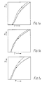
- FIG. 1a of the accompanying drawings A typical example is shown in Fig. 1a of the accompanying drawings in which the warming curve is shown as a broken line and the cooling curve is shown as a continuous line.
- tail gas At a sufficiently low pressure of the returning evaporated liquid stream, generally termed "tail gas", it is often possible to fulfil the first of the above cited conditions, i.e. to obtain overall thermal balance between the feed and the returning products. However, in many cases this does not lead to the fulfilment of the other two conditions. Frequently, a "crossover" occurs, in that, over a certain temperature interval, generally in the lower temperature region, the warming curve comes to lie to the right of the cooling curve, thus rendering the process inoperable. (See Fig. 1b of the drawings.)
- US-A-3373574 is concerned with a process for the separation of methane and C 2 hydrocarbon condensibles (i.e. ethylene and ethane) from a gas mixture with hydrogen.
- the mixture is first cooled to about the liquefaction temperature of methane and the hydrogen gas and liquefied material separated and then in a second step the liquefied material is subjected to Joule-Thomson expansion to a sufficiently lower pressure to form a methane-rich vapour fraction and a C 2 hydrocarbon-enriched liquid fraction.
- the said liquefied material is rewarmed to effect partial evaporation prior to the separation by heat exchange with the cooling gas mixture and thereby provides a part of the refrigeration for the system. Further refrigeration is provided by the methane-rich vapour fraction recovered from the second step.
- a conventional compression-condensation closed refrigeration loop is provided to furnish any further requirement for refrigeration.
- US-A-3914949 is concerned with a process for liquefying natural gas and also employs a closed loop refrigeration process.
- One case to which the invention may be applied is where for a part of the temperature range through which the feed gas mixture is being cooled, the sum of the enthalpies of the returning streams is less than the enthalpy of the feed gas mixture, whereby the warming curve lies to the right of the cooling curve for said part of the temperature range, i.e. the case illustrated in Figure 1(b).
- Another case to which the invention may be applied is where for a part of the said temperature range, the sum of the enthalpies of the returning streams, while not being less than the enthalphy of the feed gas mixture, is not sufficiently greater for the process to be operable practically, e.g. because an uneconomically high or infinite heat exchange area would be required.
- a method of rendering operable a process for the separation of a gas mixture at superatmospheric pressure which comprises cooling the mixture from a first temperature T 1 to a sub-ambient temperature T 2 to partially condense it, separating thus formed condensate from uncondensed vapour, subjecting separated condensate to Joule-Thomson expansion and passing thus-expanded condensate and uncondensed vapour as returning streams in indirect counter-current heat exchange relationship with the feed gas mixture to cool the latter and evaporate the expanded condensate, and which process is inoperable by reason that in a lower part of the temperature range between T 1 and T 2 the sum of the enthalpies of the said returning streams is not sufficiently greater than the enthalpy of the feed gas mixture, the method comprising providing a closed heat pump cycle in which a multi-component gaseous medium is condensed at a superatmospheric pressure P 1 and over a first temperature interval ⁇ T A in indirect countercurrent
- additional refrigeration is provided towards the cold end of the process and automatically rem Q ved towards the warm end, and by appropriate choice of the temperature intervals ⁇ T A and OT B and of the amount of refrigeration provided in the temperature interval ⁇ T B and removed in the temperature interval AT A , it is possible to eliminate any "cross-over" that would otherwise occur at the lower temperatures, or resolve any difficulties due to the warming and cooling curves approaching each other too closely at such lower temperatures, without widening the gap between the warming and cooling curves at the higher temperatures.
- composition of the multi-component gaseous mixture employed as the heat pump medium and the values for pressures P, and P 2 are then chosen such that at P, the medium condenses in the interval ⁇ T A and at P 2 it evaporates in the interval ⁇ T B .
- the composition will usually be selected on a trial and error basis but as a general rule it may be said that in the most widely applicable area of the invention, namely for processes for the separation of hydrogen rich gas from a feed gas stream containing hydrogen, the heat pump medium will usually comprise a mixture of light hydrocarbons (i.e. hydrocarbons containing 1 to 4 carbon atoms) and a minor proportion of nitrogen.
- the amount of refrigeration provided and removed by the heat pump medium in the intervals ⁇ T B and AT A , respectively, may be controlled by adjustment of the volume of heat pump medium circulating and/or the rate of circulation of the medium.
- the heat pump In general it will be preferred to operate the partial condensation process in heat balance without the heat pump, and thus the heat pump must also be balanced; i.e. so that the heat removed in the lower temperature interval ⁇ T B is equal to that introduced in the higher temperature interval ⁇ T A .
- the heat pump may be designed and operated so that the heat removed exceeds the heat introduced, or vice versa, to balance an otherwise unbalanced process.
- the heat pump may be used to provide additional refrigeration.
- the process of the invention is particularly appropriate for those separation processes in which both ⁇ T A and ⁇ T B are below ambient temperature since then the heat equivalent of the net mechanical work consumed by the heat pump cycle may conveniently be rejected to a heat sink at ambient temperature, e.g. in a cold water cooler.
- Additional cooling of the compressed heat pump medium at the pressure P 1 and/or superheating of the evaporated heat pump medium at the pressure P 2 may be required to achieve condensation and/or evaporation of the heat pump medium within the desired temperature ranges.
- the cooling of the feed gas mixture by the returning vapour and expanded condensate streams may be effected in a single heat exchanger or two or more exchangers which may be in series and condensate formed in any heat exchanger may be removed, if desired, before the gas mixture is passed to a subsequent exchanger.
- the process is particularly but not exclusively applicable to the separation of hydrogen-rich gas streams containing hydrogen, especially those evolved in the gasification of coal or other solid hydrocarbon fuel and hydrogen-containing gas streams produced in the course of oil refining and petrochemical processes.
- the problem of "cross-over” tends to be particularly acute in the case of hydrogen-containing gas streams containing hydrocarbons and less than 65 mole % hydrogen, e.g. from 35 to 65 mole %.
- the process overcomes the problem of avoiding "cross-over" at low temperatures without causing an undesirable widening of the gap between the warming and cooling curves at higher temperatures, and is more energy efficient than the alternative of reducing the pressure to which the condensate from the partial condensation is expanded and thereafter recompressing the evaporated condensate where it is desired to recover the tail gas at a higher pressure.
- the feed gas mixture enters at super-atmospheric pressure and ambient temperature through lines 11, is cooled and partially condensed in exchangers 1 and 2, and liquid and vapour are separated in the vessel 5.
- the vapour is therefore returned through both exchangers in line 12 without a significant drop in pressure.
- the condensate is expanded in valve 7 to the maximum pressure required for the overall heat balance of the process and is then returned in line 14 through exchangers 2 and 1, in which it is evaporated and warmed to near ambient temperature and recovered as tail gas.
- a much smaller compressor 6 is installed, which compresses a multi-component gaseous heat pump medium to a first pressure P i .
- the heat of compression is rejected to cooling water in exchanger 4, and the compressed heat pump medium is passed in line 16 to enter the warm end of exchanger 2 wherein it is condensed over a first temperature interval AT A (and if desired subcooled) in counter-current heat exchange relationship with the returning vapour and expanded condensate streams in lines 12 and 14.
- the condensed medium is withdrawn through line 17 from an intermediate point along heat exchanger 2 and the condensate is then expanded to a lower pressure P 2 in valve 8 and thereafter passed back through line 18 to enter the cold end of exchanger 2 wherein it is evaporated over a second temperature interval OT B (which is lower than LlTA) in indirect counter-current heat exchange relationship with the feed gas mixture flowing in line 11 and also superheated.
- OT B which is lower than LlTA
- the heat pump medium in line 18 passes back through the entire length of heat exchangere 2 and is recovered from the warm end in line 19 whence it is returned to the compressor 6 through line 20.
- heat pump medium For the heat pump medium to be at the appropriate temperature when it enters heat exchanger 2 it may be necessary to provide a precooling step upstream of heat exchanger 2. Similarly, for the evaporated heat pump medium recovered from the warm end of said heat exchanger to be at an appropriate temperature at the inlet to the compressor, it may be necessary to warm it. In the arrangement illustrated, such pre-cooling and warming is achieved in heat exchanger 3 where the compressed heat pump medium in line 15 is pre-cooled by the same medium returning at low pressure in line 19. It will be apparent to those skilled in the art that many modifications of the illustrated arrangement of heat exchangers are possible without departing from the invention. For example, heat exchanger 3 may be combined with heat exchanger 1 in the same vessel as a single multi-stream unit. Also, heat exchanger 2 may be split into two exchangers in series whereby line 16 passes through one of the exchangers and line 18 passes through both.
- the cooling and warming curves can be brought to the desired relative position to make the plant operable and the power consumption is significantly less than would be the case if the tail gas itself were expanded to a lower pressure and recompressed.
- a feed gas mixture in line 11, available at 52 bar and 40°C, has the following composition:-
- the flow rate is 14400 kg. mol/h r.
- a heat pump cycle is provided as illustrated in the drawing with a heat pump medium having the following composition: and the flow rate of 1480 kg.mol/hr.
- the heat pump compressor operates between 1.5 bar at which the medium evaporates in the range 98-166°K and 25 bar (P 1 ) at which the medium condenses in the range 221-165°K.
- the heat pump medium enters exchanger 2 at its dew-point of 221°K, and leaves at the intermediate point, subcooled to 125°K.
- the temperatures of the streams at various points in the arrangement are as follows.
- the power consumed by the heat pump compressor is 4320 kw and the power consumed by the tail gas compressor in compressing the tail gas from 15 to 52 bar is 8300 kw, giving a total power consumption for the process of 12620 kw.
- the condensate would have to be expanded to 2.5 bar. This would lead to a power consumption of 19600 kw for compressing the tail gas. Even if a part of the tail gas only is expanded to 2.5 bar and the rest to an intermediate pressure, the power consumption could be reduced to 16800 kw, but this is still significantly higher than that required using the heat pump.
Landscapes
- Engineering & Computer Science (AREA)
- Physics & Mathematics (AREA)
- Mechanical Engineering (AREA)
- Thermal Sciences (AREA)
- General Engineering & Computer Science (AREA)
- Chemical & Material Sciences (AREA)
- Organic Chemistry (AREA)
- Combustion & Propulsion (AREA)
- Inorganic Chemistry (AREA)
- Separation By Low-Temperature Treatments (AREA)
Claims (9)
Applications Claiming Priority (2)
| Application Number | Priority Date | Filing Date | Title |
|---|---|---|---|
| GB8033468 | 1980-10-16 | ||
| GB8033468 | 1980-10-16 |
Publications (4)
| Publication Number | Publication Date |
|---|---|
| EP0050468A2 EP0050468A2 (de) | 1982-04-28 |
| EP0050468A3 EP0050468A3 (en) | 1982-08-04 |
| EP0050468B1 EP0050468B1 (de) | 1984-12-12 |
| EP0050468B2 true EP0050468B2 (de) | 1987-10-07 |
Family
ID=10516725
Family Applications (1)
| Application Number | Title | Priority Date | Filing Date |
|---|---|---|---|
| EP81304771A Expired EP0050468B2 (de) | 1980-10-16 | 1981-10-13 | Gasgemischtrennung durch Teilkondensation |
Country Status (4)
| Country | Link |
|---|---|
| EP (1) | EP0050468B2 (de) |
| CA (1) | CA1174159A (de) |
| DE (1) | DE3167736D1 (de) |
| GB (1) | GB2086028B (de) |
Families Citing this family (2)
| Publication number | Priority date | Publication date | Assignee | Title |
|---|---|---|---|---|
| JPS58183901A (ja) * | 1982-04-14 | 1983-10-27 | コステイン・ペトロカ−ボン・リミテッド | 分縮による混合ガス分離法 |
| DE3344033A1 (de) * | 1983-12-06 | 1985-06-13 | Hans Dr. 4235 Schermbeck Remstedt | Verfahren zur wassergewinnung aus der luftfeuchte durch einen kompressor mit angeschlossener kuehlvorrichtung |
Family Cites Families (4)
| Publication number | Priority date | Publication date | Assignee | Title |
|---|---|---|---|---|
| DE499819C (de) * | 1927-04-26 | 1931-06-17 | Linde Eismasch Ag | Verfahren und Vorrichtung zur Zerlegung von Gasgemischen |
| US3373574A (en) * | 1965-04-30 | 1968-03-19 | Union Carbide Corp | Recovery of c hydrocarbons from gas mixtures containing hydrogen |
| US3914949A (en) * | 1971-02-19 | 1975-10-28 | Chicago Bridge & Iron Co | Method and apparatus for liquefying gases |
| GB2009909A (en) * | 1977-11-24 | 1979-06-20 | Petrocarbon Dev Ltd | Improving the purity of impure hydrogen streams |
-
1981
- 1981-10-13 DE DE8181304771T patent/DE3167736D1/de not_active Expired
- 1981-10-13 GB GB8130901A patent/GB2086028B/en not_active Expired
- 1981-10-13 EP EP81304771A patent/EP0050468B2/de not_active Expired
- 1981-10-14 CA CA000387845A patent/CA1174159A/en not_active Expired
Also Published As
| Publication number | Publication date |
|---|---|
| CA1174159A (en) | 1984-09-11 |
| EP0050468A2 (de) | 1982-04-28 |
| DE3167736D1 (en) | 1985-01-24 |
| GB2086028B (en) | 1984-03-28 |
| GB2086028A (en) | 1982-05-06 |
| EP0050468B1 (de) | 1984-12-12 |
| EP0050468A3 (en) | 1982-08-04 |
Similar Documents
| Publication | Publication Date | Title |
|---|---|---|
| US4435198A (en) | Separation of nitrogen from natural gas | |
| US4430103A (en) | Cryogenic recovery of LPG from natural gas | |
| US6105391A (en) | Process for liquefying a gas, notably a natural gas or air, comprising a medium pressure drain and application | |
| USRE30140E (en) | Method for cooling a gaseous mixture to a low temperature | |
| US3205669A (en) | Recovery of natural gas liquids, helium concentrate, and pure nitrogen | |
| US3721099A (en) | Fractional condensation of natural gas | |
| US5983665A (en) | Production of refrigerated liquid methane | |
| RU2224961C2 (ru) | Способ удаления летучих компонентов из природного газа | |
| US6363744B2 (en) | Hydrocarbon separation process and apparatus | |
| RU2215952C2 (ru) | Способ разделения потока многокомпонентного исходного материала под давлением путем использования дистилляции | |
| RU2702074C2 (ru) | Способ (варианты) и устройство (варианты) для получения обедненного азотом продукта спг | |
| US3516262A (en) | Separation of gas mixtures such as methane and nitrogen mixtures | |
| US3929438A (en) | Refrigeration process | |
| US4622053A (en) | Separation of hydrocarbon mixtures | |
| US4592767A (en) | Process for separating methane and nitrogen | |
| JP2000180048A (ja) | ガス液化のための2つの混合冷媒を使用するサイクル | |
| AU701090B2 (en) | Method and installation for the liquefaction of natural gas | |
| US20190128600A1 (en) | Method and apparatus for separating hydrocarbons | |
| US3373574A (en) | Recovery of c hydrocarbons from gas mixtures containing hydrogen | |
| EP0161100A2 (de) | Destillationsverfahren mit hohem thermodynamischen Wirkungsgrad | |
| US3808826A (en) | Refrigeration process | |
| US5579655A (en) | Process and apparatus for the liquefaction of hydrogen | |
| US4331461A (en) | Cryogenic separation of lean and rich gas streams | |
| US5030339A (en) | Separation of gas and oil mixtures | |
| US5329775A (en) | Cryogenic helium production system |
Legal Events
| Date | Code | Title | Description |
|---|---|---|---|
| PUAI | Public reference made under article 153(3) epc to a published international application that has entered the european phase |
Free format text: ORIGINAL CODE: 0009012 |
|
| AK | Designated contracting states |
Designated state(s): DE FR IT NL |
|
| PUAL | Search report despatched |
Free format text: ORIGINAL CODE: 0009013 |
|
| AK | Designated contracting states |
Designated state(s): DE FR IT NL |
|
| 17P | Request for examination filed |
Effective date: 19830119 |
|
| ITF | It: translation for a ep patent filed | ||
| GRAA | (expected) grant |
Free format text: ORIGINAL CODE: 0009210 |
|
| AK | Designated contracting states |
Designated state(s): DE FR IT NL |
|
| REF | Corresponds to: |
Ref document number: 3167736 Country of ref document: DE Date of ref document: 19850124 |
|
| ET | Fr: translation filed | ||
| NLT1 | Nl: modifications of names registered in virtue of documents presented to the patent office pursuant to art. 16 a, paragraph 1 |
Owner name: COSTAIN PETROCARBON LIMITED TE MANCHESTER, GROOT-B |
|
| PLBI | Opposition filed |
Free format text: ORIGINAL CODE: 0009260 |
|
| 26 | Opposition filed |
Opponent name: LINDE AKTIENGESELLSCHAFT, WIESBADEN Effective date: 19850910 |
|
| NLR1 | Nl: opposition has been filed with the epo |
Opponent name: LINDE AKTIENGESELLSCHAFT |
|
| REG | Reference to a national code |
Ref country code: FR Ref legal event code: CD |
|
| PUAH | Patent maintained in amended form |
Free format text: ORIGINAL CODE: 0009272 |
|
| STAA | Information on the status of an ep patent application or granted ep patent |
Free format text: STATUS: PATENT MAINTAINED AS AMENDED |
|
| 27A | Patent maintained in amended form |
Effective date: 19871007 |
|
| AK | Designated contracting states |
Kind code of ref document: B2 Designated state(s): DE FR IT NL |
|
| ITF | It: translation for a ep patent filed | ||
| PGFP | Annual fee paid to national office [announced via postgrant information from national office to epo] |
Ref country code: NL Payment date: 19871031 Year of fee payment: 7 |
|
| ET3 | Fr: translation filed ** decision concerning opposition | ||
| NLR2 | Nl: decision of opposition | ||
| NLR3 | Nl: receipt of modified translations in the netherlands language after an opposition procedure | ||
| PG25 | Lapsed in a contracting state [announced via postgrant information from national office to epo] |
Ref country code: NL Effective date: 19890501 |
|
| NLV4 | Nl: lapsed or anulled due to non-payment of the annual fee | ||
| PG25 | Lapsed in a contracting state [announced via postgrant information from national office to epo] |
Ref country code: FR Free format text: LAPSE BECAUSE OF NON-PAYMENT OF DUE FEES Effective date: 19890630 |
|
| PG25 | Lapsed in a contracting state [announced via postgrant information from national office to epo] |
Ref country code: DE Effective date: 19890701 |
|
| REG | Reference to a national code |
Ref country code: FR Ref legal event code: ST |