EP0050508A2 - Zuführeinrichting für Vorlagen in einer Kopiermaschine - Google Patents
Zuführeinrichting für Vorlagen in einer Kopiermaschine Download PDFInfo
- Publication number
- EP0050508A2 EP0050508A2 EP81304873A EP81304873A EP0050508A2 EP 0050508 A2 EP0050508 A2 EP 0050508A2 EP 81304873 A EP81304873 A EP 81304873A EP 81304873 A EP81304873 A EP 81304873A EP 0050508 A2 EP0050508 A2 EP 0050508A2
- Authority
- EP
- European Patent Office
- Prior art keywords
- feeder
- documents
- original
- order
- exposure surface
- Prior art date
- Legal status (The legal status is an assumption and is not a legal conclusion. Google has not performed a legal analysis and makes no representation as to the accuracy of the status listed.)
- Withdrawn
Links
Images



Classifications
-
- G—PHYSICS
- G03—PHOTOGRAPHY; CINEMATOGRAPHY; ANALOGOUS TECHNIQUES USING WAVES OTHER THAN OPTICAL WAVES; ELECTROGRAPHY; HOLOGRAPHY
- G03B—APPARATUS OR ARRANGEMENTS FOR TAKING PHOTOGRAPHS OR FOR PROJECTING OR VIEWING THEM; APPARATUS OR ARRANGEMENTS EMPLOYING ANALOGOUS TECHNIQUES USING WAVES OTHER THAN OPTICAL WAVES; ACCESSORIES THEREFOR
- G03B27/00—Photographic printing apparatus
- G03B27/32—Projection printing apparatus, e.g. enlarger, copying camera
- G03B27/52—Details
- G03B27/62—Holders for the original
- G03B27/6207—Holders for the original in copying cameras
- G03B27/625—Apparatus which relate to the handling of originals, e.g. presence detectors, inverters
Definitions
- This invention relates to an original document feeder for copying machines, and more particularly to a feeder for automatically positioning an original document on the exposure surface, comprising a plurality of friction wheels which rotate in order to feed an original document on to an exposure surface, and reference means which are selectively operable in order to align said documents in the feed direction.
- the original document feeder according to the invention obviates the aforesaid drawbacks, and is characterised in the manner set forth in claim l.
- the reference numeral 6 indicates a copying machine comprising an original feeder contained in a plastics cover 10 for covering the originals. This is pivoted on a shaft 8 carried by the copying machine 6, and is counterbalanced by a pair of springs 9 wound on the shaft 8 (Fig. 4).
- a surface 15 for exposing the originals is formed by a flat transparent support 16 (Fig. 2), and is fixed in a semi-rigid manner to the upper structure 17 of the copying machine. In its lateral part (to the right in Fig. 2), the structure 17 comprises an inclined surface 20 for introducing the originals 21.
- a frame 25 fixed to the cover 10 supports all the moving parts of the feeder, as is described hereinafter.
- Each wheel 31 (Fig. 3) is formed from a hub 31A keyed on to the shaft 30.
- a hollow frusto-conical crown 31B of small thickness relative to its outer diameter is connected to the hub 31A.
- the crown 31B is bounded by a cylindrical surface 31C , which is coaxial to the hub,andconstitutes the outer surface for dragging the sheet 21.
- the frusto-conical shape of the crown 3113 gives the wheels 31 a considerable elastic yieldability in the radial direction, so that they are able to deflect to a greater or lesser degree with the passage of originals of greater or lesser rigidity.
- the shaft 30 is rotated by an electric motor 33 (Fig. 2) by way of a belt 34 which winds about two pulleys 35 and 360
- a transverse channel 40 is provided parallel to the shaft, 30 on the inclined surface 20, in a position corresponding with the wheels 31.
- the channel 40 has a cross-section in the form of a circular arc profile with its centre on the axis of the shaft 30, and is positioned such as to leave a gap of about 1 mm from the edge 31C (Fig. 3) of the pulleys 31.
- a metal guide 42 fixed to a side wall 43 of the cover 10, is disposed a short distance from the surface 20 in order to constitute a slot 44 for introducing the originals 21.
- a movable curved plate 46 for adjusting and aligning the originals is fixed to a shaft 47 rotatable on the frame 25.
- the free end 44' of the curved plate 46 is arranged, when in its rest position, to intercept the path of the original 21 immediately after the wheels 31 in the introduction direction.
- an electromagnet 50 rotates the curved plate 46 clockwise in order to withdraw it from the path of the original 21, and to permit the original to advance on the exposure surface 15 in the manner described hereinafter.
- an end 53' of a feeler lever 53 pivoted on a fixed pin 54 is raised.
- the end 53" of the lever 53 operates a microswitch 52 in. order to feed a signal INSE over a wire 55 leaving the microswitch 52.
- the original sheet 21 is conveyed on to the exposure surface 15 by a set of belts 60 (Fig. 2) which wind about two corresponding groups of pulleys 62 and 64 (Figs. 2, 4).
- the pulleys 62 are mounted on a drive shaft 65, which is rotated by a motor 66 by way of a worm-helical gear pair 69.
- a movable plate 74 of elongated shape is disposed along an edge 16' of the exposure surface 16 (to the left of Figs. 2 and 4) transversely to the direction of motion of the originals.
- the plate 74 which hereinafter will be known as the rear register, is provided with a plurality of lugs 74' projecting into the free spaces between the belts 60 above the exposure surface 16, in such a manner that when in their normal position they intercept the path of the originals 21.
- the register 74 is pivoted on ends 75 of a bar 75' of an auxiliary frame 76 formed by a'pair of side pieces 77 rigidly connected together by the bar 75' and by a shaft 78.
- the shaft 78 is pivoted on two appendices 17' of the structure 17, in such a manner that the frame 76 can rotate about the axis of the shaft 78.
- the register 74 can therefore move downwards (Fig. 2) as a result of the clockwise rotation of the frame 76, and can rotate about the ends 75 through a small angle, overcoming the action of a spring 80 which maintains it in its normal position as shown by full lines in Fig. 2.
- a L-shaped lever 83 is pivoted to a support 81 fixedto the structure 17, and is retained in its normal position indicated in Fig. 2 by a lug 85 of the register 74, which engages an-end 84 of the lever 83, so preventing it from rotating clockwise by the action of a spring 92 connected to an arm 86 of the lever 83.
- a peg 88 on the arm 86 engages a lever 89 of a microswitch 90.
- a bar 95 is connected at one end 96 to an electromagnet 98, and is supported at a slot 102 at the other end 97, by a pin 100 fixed to one of the side pieces 77.
- a spring 105 is stretched between the end 97 of the bar 95 and an appendix 77' of the auxiliary frame'76.
- the other end 96 of the bar 95 is connected by a spring 106 to a fixed point of the structure 17.
- the spring 106 has a rate greater than that of the spring 105, so that when the electromagnet 98 is deenergised, as described hereinafter, the spring 106 pulls the bar 95 towards the right (Fig. 2), and the spring 105 has to yield when the register 74 is unable to rise because of the presence of an unexpelled original.
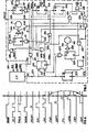
- Fig. 5 shows a logic unit 200 for handling the signals emitted by the microswitches 52, 58, 90 and for generating control: signals for the electromagnets 50, 98 and the motors 33 and 66.
- the logic unit 200 is also connected by two wires 202, 203 to a microprocessor CP which controls the general logic of the copying machine 6 (Fig. 1).
- FF flip-flop
- the output Q of the FF 207 goes to logic level 1 and activates a power unit 209 of known type in order to operate the motor 33.
- the motor 33 rotates the pulleys 31 (Fig. 2) in a clockwise direction.
- the sheet 21 is dragged by friction by means of the wheels 31 through the channel 40, in which it is bent elastically according to the curvature of the slot itself.
- the combination of the wheels 31 with the channel 40 enables originals of any substance to be fed, and in particular originals formed from very light sheets such as the copy paper used for typed copies, without these becoming bent or crumpled.
- each sheet of paper behaves resiliently, with a rigidity approximately proportional to the substance of the paper. Consequently, when a sheet 21 is introduced between the wheels 31 and the channel 40, by virtue of the deformation which it undergoes it exerts against the cylindrical surface 31C (Fig. 3) of the wheels 31 a certain resilient reaction which, combined with the coefficient of friction between the wheels 31 and the sheet 21, generates the forces which drag the sheet.
- the dragging force also depends on the substance of the sheets. Sheets of normal substance, i.e. between 60 and 80 g/m 2 , are dragged with a greater force than copy paper sheets having a lower substance of between 30 and 50 C/m 2 . Moreover, the dragging force does not exceed a determined value, so that when the sheet halts against the curved plate,46, the pulleys slip on the sheet without damaging it. Slightly before touching the curved plate 44 with its front edge, the sheet 41 raises the.feeler 56', which operates the microswitch 58 in order to emit the signal PRES over the wire 59. This signal is required to perform two functions, namely to stop the motor 33 and indicate the presence of the original against the curved plate 46. For this purpose, the signal PRES (Fig. 5) is fed to an OR gate 211 which resets the FF 207, so that the circuit 209 becomes deactivated and the motor 33 stops.
- the signal PRES is also fed to the set input of a FF 213, to an AND gate 215 and, inverted, to an AND gate 217. Consequently, the FF 213 puts its output Q at 1, to illuminate a lamp SIGN in order to indicate the presence of the original in the slots 44 in the correct position for subsequent feeding on to the exposure surface.
- the operator sets the number of required copies on the control panel T and presses the PRINT button 108 (Fig. 1) which energises the electromagnet 50 by means of an FF 219 (Fig. 2). Consequently, the bar 51 is moved to the left in order to raise the curved plate 46.
- the signal PRINT is fed to the OR gate 205 (Fig. 5), to the reset input R of the FF213, and to an OR223 connected to an FF225.
- the FF 207 and FF 225 respectively activate the power units 209 and 210, by which the motors 33 and 66 are rotated. Finally the lamp SIGN is extinguished by the FF 213, because this is reset by the signal PRINT.
- the motor 33 (Fig. 2) causes the original 21 to advance until it is taken up and dragged by the belts 60 driven by the motor 66.
- the signal PRINT activates a timer circuit 230 (Fig. 5) to define a first time interval t 0 for deactivating the motor 66 after this interval.
- the signal ESP at logic level 1 performs the following simultaneous functions:
- the signal ESP stops the two motors 33 and 66, resetting the corresponding FF 207 and FF 225 respectively by means of the OR gates 211 and 212. In addition, it resets the FF 219 to deenergise the electromagnet 50.
- the signal TIM is fed to the FF 207 and FF 225 in order to respectively stop the motors 33 and 66 of the AND gate,214, and is also fed to the FF 216 and to the OR gate 218 in order to light the lamp JAM.
- the original can again be inserted into the slot 44 for a new copying stage.
- the electromagnet 98 moves the bar 95 towards the left (Fig. 2) ; , overcoming the action of the spring 106. Consequently, the spring 105 is released, to enable the auxiliary frame.76 to rotate clockwise about the shaft 78.by the effect of its own weight, so that the register 74 is lowered and removes the lugs 74' from the path of the sheet 21, which is expelled by the belts 60 towards the outlet 79 (Fig. 2).
- the spring 80 rotates it in a clockwise direction, so that the lug 85 engages the end of the lever 86, so that it becomes set to return the lever 83 to its normal position when the electromagnet 91 is deenergised. If the expulsion stage takes place in a regular manner within the time interval t 1 predetermined by the counter 232, the FF 227 becomes reset when CNT goes to level.1, and the electromagnet 98 is thus,deenergised. The FF 225 is also reset in order to stop the motor 66.
- the spring 106 pulls the bar 95 to the right, so putting the spring 105 under tension, and this rotates the auxiliary frame 77 in an anti-clockwise direction, so that the register 74 becomes raised and returned to its original position shown by full lines.
- the signal CNT is then fed, suitably delayed by a delay circuit 241 of known type, to the AND gate 234 which lights the lamp JAM in order to indicate . a jammed condition.
- Fig. 6 shows the timing of the signals handled by the cirquit 200 of Fig. 5, and in addition the pattern of the voltages M1, M2 applied respectively to the motors 33 and 66 and of the voltages EM1, EM2 applied respectively to the electromagnets 50 and 98 are also shown.
- Fig 7 shows a modification of the original feeder according to a further aspect of the invention.
- Stops disposed between the belts 60 and aligned transversely to the direction of motion of the sheet 21, are provided on the structure 17 immediately downstream of the pulleys 64 in the direction of movement of the sheet 21.
- Each stop 19 is formed by a ram 160 smoothly connected to the slide surface 18 for the sheet 21 and terminating in a step 162 at the joining line between the structure 17 and the transparent surface 16.
- the step 162. has a height slightly greater than the thickness of the belts 60, and its purpose is to align and correctly position the sheet 21 on the surface 16.
- the stop 19 allows passage of a sheet under movement from right to left in Fig. 7, whereas it constitutes a reference stop for the sheet when moving in the opposite direction to the preceding.
- the distance between the step 162 and the end 167 of the lever 164 is greater than the length of the maximum copyable format.
- the document 21 to be copied is dragged by the belts 60 in the manner already described, until its front edge intercepts the end 167 of the lever 164, which closes the microswitch 170.
- the microswitch 170 then feeds a signal INV over a wire 91' connected to a conventional logic circuit comprising a flip-flop circuit and a timer, not shown on the drawings, this signal stopping the motors 66 and 33 and restarting only the motor 66 in the opposite direction for a short period of time, for example 1 second.
- the original 21 is moved backwards against the step 162, to be correctly positioned for copying.
- the copier can initiate the copying cycle in the manner already described, and after copying one or more copies the original document is expelled through the slot 79 by means of the belt 60.
Landscapes
- Physics & Mathematics (AREA)
- General Physics & Mathematics (AREA)
- Delivering By Means Of Belts And Rollers (AREA)
- Registering Or Overturning Sheets (AREA)
- Exposure Or Original Feeding In Electrophotography (AREA)
- Separation, Sorting, Adjustment, Or Bending Of Sheets To Be Conveyed (AREA)
- Feeding Of Articles By Means Other Than Belts Or Rollers (AREA)
- Holders For Sensitive Materials And Originals (AREA)
Applications Claiming Priority (2)
| Application Number | Priority Date | Filing Date | Title |
|---|---|---|---|
| IT6859780 | 1980-10-20 | ||
| IT68597/80A IT1129327B (it) | 1980-10-20 | 1980-10-20 | Alimentatore di originali per macchine copiarici |
Publications (2)
| Publication Number | Publication Date |
|---|---|
| EP0050508A2 true EP0050508A2 (de) | 1982-04-28 |
| EP0050508A3 EP0050508A3 (de) | 1983-05-11 |
Family
ID=11309980
Family Applications (1)
| Application Number | Title | Priority Date | Filing Date |
|---|---|---|---|
| EP81304873A Withdrawn EP0050508A3 (de) | 1980-10-20 | 1981-10-19 | Zuführeinrichting für Vorlagen in einer Kopiermaschine |
Country Status (4)
| Country | Link |
|---|---|
| US (1) | US4456243A (de) |
| EP (1) | EP0050508A3 (de) |
| JP (1) | JPS57104151A (de) |
| IT (1) | IT1129327B (de) |
Cited By (2)
| Publication number | Priority date | Publication date | Assignee | Title |
|---|---|---|---|---|
| EP0064591A1 (de) * | 1981-05-11 | 1982-11-17 | International Business Machines Corporation | Methode und Einrichtung zum registerhaltigen Fördern von Bogen |
| DE3505650A1 (de) * | 1984-02-21 | 1985-08-29 | Kabushiki Kaisha Toshiba, Kawasaki, Kanagawa | Dokumenten-zufuehrgeraet zur verwendung bei abbildenden geraeten |
Families Citing this family (1)
| Publication number | Priority date | Publication date | Assignee | Title |
|---|---|---|---|---|
| US4634112A (en) * | 1985-10-17 | 1987-01-06 | Morton Silverberg | Plural belt document feeder |
Family Cites Families (11)
| Publication number | Priority date | Publication date | Assignee | Title |
|---|---|---|---|---|
| US672529A (en) * | 1900-07-05 | 1901-04-23 | Library Bureau | Feeding mechanism for cards, &c. |
| US2953372A (en) * | 1957-08-26 | 1960-09-20 | Ncr Co | Check aligning mechanism |
| US3510125A (en) * | 1968-01-17 | 1970-05-05 | Xerox Corp | Document registration system |
| US3863912A (en) * | 1971-11-22 | 1975-02-04 | Addressograph Multigraph | Document feeder |
| US3844552A (en) * | 1972-06-12 | 1974-10-29 | Ibm | Document feed device |
| US4170414A (en) * | 1976-12-20 | 1979-10-09 | International Business Machines Corporation | Document feed controls for copy production machines |
| JPS6039613B2 (ja) * | 1977-11-05 | 1985-09-06 | 株式会社リコー | ペーパ検知機構 |
| US4171128A (en) * | 1978-01-03 | 1979-10-16 | Pitney-Bowes, Inc. | Document feeder for a copier |
| DE2843522C2 (de) * | 1978-10-05 | 1980-07-31 | Agfa-Gevaert Ag, 5090 Leverkusen | Vorlagenandruckvorrichtung für den Bildfensterbereich eines Durchlaufkopiergerätes |
| US4192607A (en) * | 1978-07-12 | 1980-03-11 | Eastman Kodak Company | Apparatus for selectively copying documents from two different document feeders |
| GB2041335B (en) * | 1979-01-29 | 1983-07-20 | Savin Corp | Automatic original document feeder for electrophotographic copier |
-
1980
- 1980-10-20 IT IT68597/80A patent/IT1129327B/it active
-
1981
- 1981-10-19 US US06/312,992 patent/US4456243A/en not_active Expired - Lifetime
- 1981-10-19 EP EP81304873A patent/EP0050508A3/de not_active Withdrawn
- 1981-10-20 JP JP56167801A patent/JPS57104151A/ja active Granted
Cited By (2)
| Publication number | Priority date | Publication date | Assignee | Title |
|---|---|---|---|---|
| EP0064591A1 (de) * | 1981-05-11 | 1982-11-17 | International Business Machines Corporation | Methode und Einrichtung zum registerhaltigen Fördern von Bogen |
| DE3505650A1 (de) * | 1984-02-21 | 1985-08-29 | Kabushiki Kaisha Toshiba, Kawasaki, Kanagawa | Dokumenten-zufuehrgeraet zur verwendung bei abbildenden geraeten |
Also Published As
| Publication number | Publication date |
|---|---|
| JPH0151416B2 (de) | 1989-11-02 |
| US4456243A (en) | 1984-06-26 |
| EP0050508A3 (de) | 1983-05-11 |
| JPS57104151A (en) | 1982-06-29 |
| IT1129327B (it) | 1986-06-04 |
| IT8068597A0 (it) | 1980-10-20 |
Similar Documents
| Publication | Publication Date | Title |
|---|---|---|
| US3469834A (en) | Sheet feeder and separator apparatus | |
| FI75543B (fi) | Foerfarande och anordning foer frammatning av en datamaskinsblankettremsa. | |
| US3556512A (en) | Document feed apparatus | |
| CA1100537A (en) | Recirculating document feeder | |
| CA1098195A (en) | Copier document sensing and control system | |
| US4449812A (en) | Paper leaf handling apparatus | |
| FI73648B (fi) | Foerfarande och anordning foer matning och hantering av dokumentark. | |
| US3556513A (en) | Document feed apparatus | |
| US4456235A (en) | Bottom-up stacker | |
| US4033694A (en) | Copier document ejector | |
| US3697063A (en) | Document handling apparatus | |
| EP0102202B1 (de) | Vorlagenzuführungs- und -justierungsgerät sowie Verfahren | |
| US4480827A (en) | Pivotal feed head for printing apparatus | |
| US3984094A (en) | Separator card retriever | |
| US3215055A (en) | Automatic copying machine | |
| US4456243A (en) | Original feeder for copying machines | |
| US3936042A (en) | Sheet feeding devices | |
| EP0083171B1 (de) | Vorlagenvorratsfach für die zeitweilige Lagerung von Vorlagenteilen | |
| CA1039323A (en) | Buckle control system | |
| US3221855A (en) | Single revolution clutch mechanism | |
| JPH0230006B2 (de) | ||
| US3396965A (en) | Sensor gauge | |
| US3378255A (en) | Paper handling apparatus | |
| US4539752A (en) | Automatic sheet transport mechanism | |
| JPS6256060B2 (de) |
Legal Events
| Date | Code | Title | Description |
|---|---|---|---|
| PUAI | Public reference made under article 153(3) epc to a published international application that has entered the european phase |
Free format text: ORIGINAL CODE: 0009012 |
|
| AK | Designated contracting states |
Designated state(s): DE FR GB |
|
| PUAL | Search report despatched |
Free format text: ORIGINAL CODE: 0009013 |
|
| AK | Designated contracting states |
Designated state(s): DE FR GB |
|
| STAA | Information on the status of an ep patent application or granted ep patent |
Free format text: STATUS: THE APPLICATION HAS BEEN WITHDRAWN |
|
| 18W | Application withdrawn |
Withdrawal date: 19831112 |
|
| RIN1 | Information on inventor provided before grant (corrected) |
Inventor name: DE SIMONE, PANTALEO |