EP0050904A1 - Revêtement, blocs et unité de surface - Google Patents
Revêtement, blocs et unité de surface Download PDFInfo
- Publication number
- EP0050904A1 EP0050904A1 EP81201215A EP81201215A EP0050904A1 EP 0050904 A1 EP0050904 A1 EP 0050904A1 EP 81201215 A EP81201215 A EP 81201215A EP 81201215 A EP81201215 A EP 81201215A EP 0050904 A1 EP0050904 A1 EP 0050904A1
- Authority
- EP
- European Patent Office
- Prior art keywords
- grids
- revetment
- grid
- sides
- vertical
- Prior art date
- Legal status (The legal status is an assumption and is not a legal conclusion. Google has not performed a legal analysis and makes no representation as to the accuracy of the status listed.)
- Granted
Links
- 239000004567 concrete Substances 0.000 claims abstract description 24
- 239000004744 fabric Substances 0.000 claims abstract description 7
- 238000004519 manufacturing process Methods 0.000 claims description 14
- 238000000034 method Methods 0.000 claims description 10
- 239000011178 precast concrete Substances 0.000 claims description 8
- 230000001413 cellular effect Effects 0.000 abstract description 10
- 239000000463 material Substances 0.000 abstract description 7
- 239000012528 membrane Substances 0.000 abstract description 6
- 101100491335 Caenorhabditis elegans mat-2 gene Proteins 0.000 description 20
- 239000002689 soil Substances 0.000 description 16
- XLYOFNOQVPJJNP-UHFFFAOYSA-N water Substances O XLYOFNOQVPJJNP-UHFFFAOYSA-N 0.000 description 16
- 230000003628 erosive effect Effects 0.000 description 7
- 239000013618 particulate matter Substances 0.000 description 7
- 230000006835 compression Effects 0.000 description 6
- 238000007906 compression Methods 0.000 description 6
- 239000011159 matrix material Substances 0.000 description 6
- 230000007704 transition Effects 0.000 description 5
- 210000004027 cell Anatomy 0.000 description 4
- 238000010586 diagram Methods 0.000 description 4
- 239000000758 substrate Substances 0.000 description 4
- 230000009105 vegetative growth Effects 0.000 description 4
- 238000004140 cleaning Methods 0.000 description 3
- 238000006073 displacement reaction Methods 0.000 description 3
- 230000007613 environmental effect Effects 0.000 description 3
- 239000011381 foam concrete Substances 0.000 description 3
- -1 gravel Substances 0.000 description 3
- 230000002706 hydrostatic effect Effects 0.000 description 3
- 239000000203 mixture Substances 0.000 description 3
- 230000004308 accommodation Effects 0.000 description 2
- 210000003850 cellular structure Anatomy 0.000 description 2
- 238000004891 communication Methods 0.000 description 2
- 238000013461 design Methods 0.000 description 2
- 239000004033 plastic Substances 0.000 description 2
- 229920003023 plastic Polymers 0.000 description 2
- 239000004576 sand Substances 0.000 description 2
- 238000004062 sedimentation Methods 0.000 description 2
- 230000006641 stabilisation Effects 0.000 description 2
- 238000011105 stabilization Methods 0.000 description 2
- 229920001875 Ebonite Polymers 0.000 description 1
- 239000011398 Portland cement Substances 0.000 description 1
- 230000015572 biosynthetic process Effects 0.000 description 1
- 235000021170 buffet Nutrition 0.000 description 1
- 238000005266 casting Methods 0.000 description 1
- 239000000919 ceramic Substances 0.000 description 1
- 238000005336 cracking Methods 0.000 description 1
- 230000007547 defect Effects 0.000 description 1
- 230000008021 deposition Effects 0.000 description 1
- 238000001514 detection method Methods 0.000 description 1
- 230000001747 exhibiting effect Effects 0.000 description 1
- 239000000945 filler Substances 0.000 description 1
- 239000012530 fluid Substances 0.000 description 1
- 230000001788 irregular Effects 0.000 description 1
- 239000002184 metal Substances 0.000 description 1
- 229910052751 metal Inorganic materials 0.000 description 1
- 150000002739 metals Chemical class 0.000 description 1
- 238000012986 modification Methods 0.000 description 1
- 230000004048 modification Effects 0.000 description 1
- 239000005445 natural material Substances 0.000 description 1
- 238000012856 packing Methods 0.000 description 1
- 230000021715 photosynthesis, light harvesting Effects 0.000 description 1
- 238000003825 pressing Methods 0.000 description 1
- 239000012858 resilient material Substances 0.000 description 1
- 230000000284 resting effect Effects 0.000 description 1
- 238000003892 spreading Methods 0.000 description 1
- 239000004575 stone Substances 0.000 description 1
Images




Classifications
-
- E—FIXED CONSTRUCTIONS
- E01—CONSTRUCTION OF ROADS, RAILWAYS, OR BRIDGES
- E01C—CONSTRUCTION OF, OR SURFACES FOR, ROADS, SPORTS GROUNDS, OR THE LIKE; MACHINES OR AUXILIARY TOOLS FOR CONSTRUCTION OR REPAIR
- E01C9/00—Special pavings; Pavings for special parts of roads or airfields
- E01C9/004—Pavings specially adapted for allowing vegetation
-
- E—FIXED CONSTRUCTIONS
- E02—HYDRAULIC ENGINEERING; FOUNDATIONS; SOIL SHIFTING
- E02B—HYDRAULIC ENGINEERING
- E02B3/00—Engineering works in connection with control or use of streams, rivers, coasts, or other marine sites; Sealings or joints for engineering works in general
- E02B3/04—Structures or apparatus for, or methods of, protecting banks, coasts, or harbours
- E02B3/12—Revetment of banks, dams, watercourses, or the like, e.g. the sea-floor
- E02B3/14—Preformed blocks or slabs for forming essentially continuous surfaces; Arrangements thereof
Definitions
- This invention pertains to cellular precast blocks or grids for use with or without interconnecting cables as revetment for stabilization of the banks of streams and rivers, levies, river bottoms, shores, ditches, channels, canals and the like and protection from erosion by water waves and currents and/or wind.
- precast concrete members including members joined into a mat or mattress by interconnecting cables or rods
- Such previously known members include precast concrete members with or without cellular structure and members cast around rods or cables utilized for interconnection of members into a mat as well as members cast with tunnels or openings through which connecting means, such as cables or rods, are passed to accomplish interconnection of members into mats.
- Known flexible concrete revetment includes an articulated concrete mattress comprising rectangular slabs- of concrete interconnected by wires as disclosed by U.S.
- Patent Nos. 2,674,856 and 2,876,628 Such revetment permits considerable erosion when cracks appear in slabs and does not accommodate hydrostatic pressure. It also inhibits establishment of vegetative growth and does not encourage sedimentation or provide velocity dissipation of flowing water.
- 3,597,928 does not , however, provide the novel means for interlocking adjacent rows of grids provided by the present invention nor does it provide for interconnection of concrete grids into a mattress with pins or parallel cables running in a single direction. It further does not provide a highly articulatable mattress of the present invention while maintaining close abutting contact between adjacent grids in the mattress, nor does it provide other desirable features of the present invention more fully described below.
- Desirable properties of revetment include provision of revetment members which mechanically interlock to create a highly stable revetment mat with or without use of additional connecting means, which mat can be interconnected with additional connecting means comprising pins or a single series of parallel'cables or rods, can be simply and inexpensively manufactured, and will function as intended by resisting displacement of revetment members by hydraulic pressure, will dissipate water flow, retain particulate matter such as soil, backfill or silt deposits and support and encourage vegetative growth. Revetment exhibiting all of these properties has not heretofore been available.
- revetment grids and mats designed to resist displacement in use by hydraulic pressure while dissipating water flow and retaining particulate matter such as soil backfill or silt deposition.
- a further object of the invention is provision of a grid and mat which will support and encourage vegetative growth.
- a further object is provision of revetment grids and mats which exhibit a highly pedestrianable surface.
- a further object is provision of a revetment mat which is highly articulatable and thus able to accommodate the topographic contours of sites where such mats are installed.
- a substantially rectangular grid having a flat bottom so that the bottom will make substantially continuous contact with the substrate soil or filter means constructed of natural materials or filter fabric or other flexible liquid-permeable membranes, if used.
- the grid has two optional vertical openings of substantially rectangular cross section through its middle portion. Such openings have two parallel sides and two opposed sides sloping inwardly from,top to bottom.
- the grid is provided with two U-shaped vertical channels on each of two long opposed sides.
- the remaining short opposed sides of the grid are provided with two-tier vertical channels which define vertical projections at each end of the short side of the grid.
- the lower portion of the sides of the grid are vertical and the upper portions slope inward.
- the grids are positioned in abutting relationship with the short sides aligned into rows staggered one half the length of the short side, and the projections at each end of the short sides are received by a portion of the two-tier vertical channels in the short side of the blocks in the abutting, staggered row, thereby interlocking adjacent rows of grids.
- grids so positioned are interconnected into mats by connecting means comprising cables or rods passed through tunnels passing horizontally through the grids parallel to the longer sides thereof. Since such cables or rods pass through staggered grids, parallel cables or rods running in a single direction serve effectively to interconnect grids into an integral matrix of staggered rows of grids.
- the U-shaped vertical channels on the long sides of the grids cooperate with like vertical channels in abutting grids to create vertical openings of rectangular cross section throughout the mat.
- grids are interconnected into mats by inserting a short pin into a portion of each of two coaxial tunnels in adjacent grids as grids are positioned by hand.
- Grids and mats may both be used with or without filter means constructed of natural materials or filter fabric or other flexible liquid-permeable membrane.
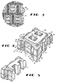
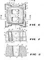
- FIG. 1 is a precast grid, shown in perspective in FIG. 4, with additional views in FIGS. 6 through 9, and 1' in FIG. 5 is a half grid.
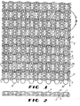
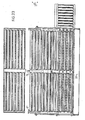
- FIG. 1 shows a mat 2 formed of staggered rows 3 of grids 1 and half grids 1' in abutting arrangement interconnected by cables 4 which pass through tunnels 5 in abutting grids 1 and half grids 1'.
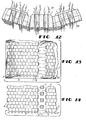
- FIGS. 13, 14.and 15 show alternative mat configurations utilizing only grids 1 and no half grids 1'.
- half grids 1' are utilized solely at the ends of alternate rows 3 to fill the area which would otherwise be created at row ends by staggering of alternate rows, thereby providing a mattress having substantially uniform sides.
- Such half grids 1' may be omitted in at least three configurations (shown in FIGS. 13, 14 and 15) which permit interconnection of mats into continuous revetment of any desired width.
- FIG. 2 shows an elevation of an end row 3 of the mattress 2 as it would appear resting on a flat surface.
- grid 1 is provided with two vertical openings 8 with continuously changing cross-section from top to bottom of grid 1.
- Such openings 8 have two opposed vertical sides 9, further illustrated in FIG. 9, and two opposed sloping sides 10, further illustrated in FIG. 8, which slope inwardly from top to bottom of the grid such that openings 8 have a substantially rectangular cross section.
- Openings 8 may alternatively be of nonrectangular cross sectional shape.
- Grid 1 is also provided with two opposed longer sides 11 which have a lower vertical surface 12 and an upper sloping surface 13 which slopes inwardly from the lower vertical surface 12 to a lower top surface 19.
- the longer sides 11 are also provided with two U-shaped vertical channels 6 which are spaced equal distances from the vertical center line of each longer side 11.
- Grid 1 has two opposed shorter sides 14 provided with lower vertical surfaces 15 and upper sloping surfaces 16.
- Each shorter side 14 is provided with a two-tier vertical channel 7 which is defined by lower vertical first and second tier surfaces 20 and 21, respectively, and upper first and second sloping surfaces 22 and 23, respectively, as well as first and second vertical incursion surfaces 17 and 18, respectively, and first and second sloping incursion surfaces 27 and 28, respectively.
- Vertical channel 7, which may alternatively be a single tier, is approximately as deep as the difference in length of the shorter side 14 and longer side 11 so that each grid 1 within a matrix of grids occupies a nominally square area.
- Grid 1 is further provided with a lower top surface 19 which is horizontal and extends around the periphery of the top of the grid and an upper top surface 24 which is slightly raised above lower top surface 19 and is substantially rectangular in outline, thus presenting a raised surface having a shape reminiscent of the numeral 8.
- Grid 1 is provided with two parallel tunnels 5, which extend horizontally through grid 1 and exit through each of the lower vertical first tier surfaces 20.
- Such tunnels 5 are of sufficient diameter to permit passage of cables or rods 4 through interconnected grids as shown in FIGS. 1, 13 and 14 but are of smaller diameter than the greatest diameter of pin 36 shown in FIGS. 16 and 17.
- FIG. 5 shows half grid 1', which is identical to one-half of the full grid 1 if it were separated in two along a plane parallel to and equally distance from the longer sides 11 of grid 1.
- grids 1 and half grids 1' are located in place, either directly on soil substrate, filter means constructed of natural material such as sand, crushed stone or gravel or on top of filter fabric 25 (shown in FIGS. 12 and 13) or other flexible liquid-permeable membrane, in interlocking abutting relationship as shown in FIGS. 1, 13, 14, 15 and 16.
- grids may be interconnected, as, for instance, by use of cables or rods 4 shown in FIGS. 1, 13, 14 and 15, by use of pins 36 as shown in FIG. 16 or, alternatively, may be placed without utilization of interconnecting means.
- These vertical cells also provide velocity dissipation of water flowing over the revetment. As flowing water passes over the cellular structure of the revetment, eddy currents will form within the vertical openings 8 and U-shaped channels 6. Formation of such eddy currents dissipates energy, thereby reducing the erosive velocity of the water sufficiently to prevent erosion of soil or other topographic structures underlying the revetment.
- the dimensional ratio of depth to width of vertical cellular openings in revetment is important to energy dissipation achieved. The preferred approximate ratio of vertical cell width to depth is less than 0.7 to 1.
- the vertical openings 8, U-shaped channels 6 and spaces 26 between grids also receive and retain soil and other particulate matter as is illustrated in FIG. 11.
- soil or particulate matter 34 unitizes adjacent grids 1 and half grids 1', if used, by providing binding between such grids.
- Stabilization of grids and mats is further enhanced by the sloping surfaces because backfill, soil or other particulate matter tends to hold grids and mats in place by the weight- of such matter pressing down on sloping sides 10 and sloping surfaces 13, 16, 22 and 23 and because sloping sides 10 form soil, backfill, particulate matter or vegetative root systems into a plug or dovetail 29 which tends to lock grid members in place when the dovetail 29 connects with underlying soil or other substate by packing or passage of vegetation 30 roots through the dovetail 29 into underlying soil structure. Eventually vegetation 30 may become sufficiently established within the backfilled soil to unitize the grids and firmly bind the revetment in place.
- lower vertical grid surfaces 12, 15, 17, 18, 20 and 21 are vertical to provide binding between abutting grids 1 and between abutting grids 1 and half grids 1', if used, in a matrix or mattress of grids.
- Such vertical surfaces between grids provide revetment which is more stable under flowing water and wave attack than revetment formed of grids with outer surfaces which slope along their entire height, because such vertical surfaces encourage buildup of binding soil and other particulate matter between abutting grids, thus creating frictional binding between abutting grids.
- the lower vertical grid surfaces 12, 15, 17, 18, 20 and 21 inhibit dislocation of grids because the grids within a matrix or mattress pivot near their vertical mid-point rather than near the bottom of the grids, and any tendency for grids to pull out of a matrix or mattress is thereby avoided.
- Upper sloping surfaces 13, 16, 22, 23, 27 and 28 which slope from the lower vertical surfaces 12, 15, 20, 21, 17 and 18 respectively toward lower top surface-19 of grid 1 permit articulation of mat 2 and accommodation of topographic irregularities when grids 1 are interconnected into mats and when grids 1 are individually placed on the substrate, while maintaining substantial abutting contact among adjacent grids. Such accommodation of topographic irregularities is illustrated in FIG. 10, which also shows vegetation 30 growing up through openings 8 in grids 1.
- Utilization of an angle of slope of 9.5 degrees from vertical for such sloping surfaces 13, 16, 22, 23, 27 and 28 permits articulation of the mat 2 into arcs having a radius of approximately three (3) feet (0.9 meters) when abutting grids 1 have substantially contiguous sloping surfaces 16, 22 and 23, or, alternatively, 13, 27 and 28 and such grids 1'have a shorter side 14 of approximately one (1) foot (0.3 meters) in length.
- Upper top surface 24 of grid 1 provides a flat and safe pedestrianable surface because the human foot will normally rest squarely on such surface of one grid or bridge upper top surfaces 24 of adjacent abutting grids.
- Lower top surface 19 forms a lower vegetation platform, as shown in FIG. 3, upon which vegetation 30 having roots extending between adjacent grids and/or through U-shaped channels 6 can initially spread. Such vegetation 30 supported by lower top surface 19 will initially provide partial cover of grids and mats and will eventually extend over upper top surface 24, along with vegetation'with roots extending through vertical openings 8, to provide a complete cover of grid systems and mats. Such vegetation contributes ecological and aesthetic value to areas protected by revetment of the present invention and provides stability to such revetment.
- FIGS. 4 and 6 through 9 Additional features of the present invention are illustrated in FIGS. 4 and 6 through 9.
- the relatively flat upper top surface 24 of grid 1 and half grid 1' exhibits a low Manning coefficient (a measure of resistance to passage of fluids over a surface) to permit maximum flow rate of water flowing over revetment of the present invention.
- An even lower Manning coefficient can be achieved by omission of the optional vertical openings 8. Omission of optional vertical openings 8 also reduces the surface area to which ice can bond in environments where ice forms.
- the grid of the present invention avoids raised castellations as are employed on the top surfaces of some known revetment, which castellations create more turbulent water flow and thus produce a higher Manning coefficient.
- the lower Manning coefficient of the present invention permits a deeper and more narrow channel to accommodate a given hydraulic flow.
- Castellations in the design of known cellular concrete revetment-members also contribute to a tendency for compression heads in the equipment for manufacturing such members to accumulate concrete in concave areas because of the difficulty of cleaning the irregular pattern of a compression head which forms such castellations.
- Such build- up of concrete in compression heads creates voids in concrete members manufactured in the heads.
- the smoother upper top surface 24 of the grid 1 and half grid 1' of present invention eliminates such build up during manufacture of the grid of concrete, and consequent creation of voids during manufacture, because cleaning of the compression head is simpler and may be performed more rapidly.
- a relatively smooth upper top surface 24 assures better compression during manufacture so that the concrete is better consolidated, which results in less grid damage from vehicle traffic, flowing water, ice floes, freeze/thaw cycles and the like.
- Ease of manufacture is further enhanced by sloping transition surface 33 between lower and upper top surfaces 19 and 24, respectively, and the radius 31 at the intersection of transition surface 33 and upper top surface 24 which permits stripping of the grid from its mold and mold cleaning during production without excessive build-up of'material in the mold where such transition surface 33 is formed.
- the absence of a sharp corner at radius 31 furthermore diminishes the tendency for stems of vegetation 30 to be cut when pressed against upper top surface 24 by pedestrian or vehicular traffic.
- Grids can be individually placed without interconnecting cables or rods 4, preassembled on cables or rods 4, individually placed with later addition of cables or rods 4 or individually placed and interconnected with pins 36 as is illustrated in FIG. 16.
- Grids 1 and half grids 1' are interconnected into a mat 2, shown in FIG. 1, mats 2', shown in FIG. 13, or mats 2" shown in FIGS. 14 and 15, by means of parallel cables or rods 4 which pass through cable tunnels 5 in each of the grids. Since the cables 4 pass through grids in staggered rows 3; parallel cables running in a single direction effectively interconnect grids into an integral matrix of staggered rows 3 of grids 1 and half grids 1' without any need for cables running transversely through the grid system to interlock adjacent lines of grids. An articulatable mat is thus unitized in both directions with cables running in a single direction, which reduced the amount of cable required to produce mats.
- This feature of the present invention also eliminates the need for providing cable tunnels transverse to tunnels 5 in grids 1 and half grids.l'. Such transverse cable tunnels are difficult and expensive to provide during production of precast concrete grids. Use of transverse cable tunnels also weakens a grid provided with such tunnels by creating additional rupture lines and effectively sectionalizing the grid.
- Mats 2 placed side by side may be connected by means of short straps, cables or rods running from the outermost cable or rod of a first mat to the outermost cable or rod of a second mat.
- Two illustrative embodiments of this connecting means are shown in FIGS. 18A and 18B.
- Mats 2 may be assembled with short straps, cables, rods or loops attached to the outermost cable or rod on each side of each mat 2. Such mats 2 may be connected side by side by connecting or binding each projecting strap, cable, rod or loop to a like connecting means projecting from the adjacent mat 2.
- FIG. 18A shows such a connection by means of straps 37.
- FIG. 18B illustrates such a connection by wire stubs 38 which are connected by connecting means 39.
- Connecting means 39 may be any suitable clamp or other conventional binding means.
- Half grids 1' may be omitted to permit side-by-side interconnection of mats into continuous revetment of any desired width. Such interconnection may be accomplished with mats constructed solely of grids 1 in either of two embodiments.
- mats 2' are produced with each of rows 3 having the same number of grids 1, such that one-half of a grid 1 in abutting rows 3 projects on alternate sides of the mat 2'. Production in this form will permit side by side interconnection of mats with like numbers of rows 3 such that the mats have co - linear top and bottom rows of grids.
- Mats 2' produced in this first alternative embodiment are interconnected in the manner illustrated in FIG. 13.
- Mats 2' are laid side by side such that one-half of each projecting grid 1 at row 3 ends of a first mat is received in the space between projecting grids 1 at row 3 ends on a second mat, thereby producing continuous rows of interconnecting grids within the two mats 2' so placed.
- a single cable or rod 4 may be passed through the coaxial tunnels 5 of grids 1 previously connected to one of the two mats, thereby positively interconnecting the first and second mats into a single mattress.
- mats 2" are produced with alternate rows 3 having one fewer grid 1 than each row 3 adjacent to such alternate rows, such that one-half of a grid 1 projects on both ends of alternate rows.
- This configuration also permits side-by-side interconnection with co-linear top and 'bottom mat rows.
- Mats 2" produced in the second alternative configuration may be interconnected, as is illustrated in FIG. 14, by placing a first mat 2" in side by side relationship with a second mat 2" such that projecting grids 1 at row 3 ends of the first mat are in side by side abutting relationship with projecting grids 1 at row 3 ends of the second mat, thereby defining full-grid openings in alternate rows.
- a loose grid 1 may then be inserted in each such opening, and cables or rods 4 may be passed through tunnels 5 of such loose grids 1 and through abutting grids having tunnels 5 coaxial with such loose grids.
- Interconnection of mats 2" placed in side by side abutting relationship may alternatively be accomplished as illustrated in FIG. 15 by pouring concrete 35 into the full-grid openings in alternate rows and permitting such concrete 35 to cure, thereby bonding row end grids 1 of one mat 2" to abutting row end grids 1 of another mat 2".
- the. interlocking feature of the present invention enables a mat to maintain its integrity even if the cables or rods 4 or pins 36 deteriorate or otherwise cease to interconnect grids.
- revetment of the present invention is placed with rows 3 parallel to the direction of the flow of water, and such flowing water cannot remove a single grid 1 or half grid 1' on the downstream side of the revetment because of interlocking with adjacent grids.
- the mat 2 or revetment of individually placed grids cannot fail progressively from the-downstream side.
- Grids 1 and half grids 1', if used, within mat 2 are not affixed to cables or rods 4 and are free to move along cables or rods 4 and thereby adjust themselves in place while permitting differential spreading of the grids within the tolerances permitted by the interlocking of the grids.
- the cables or rods 4 may be looped where they exit the mat 2 and bound into loops 32, as is shown on FIG. 1, by conventional clamps or other means, not shown. Such loops 32 permit attachment to the mat 2 for lifting and placement by a conventional strongback. Loops 32 may later be cut to permit attachment, by clamps or other means, of the cable 4 ends projecting from one mat 2 to the cable 4 ends projecting from a second mat 2 placed end-to-end with the first. When steep slopes are encountered, anchors may be set and cables or rods 4 attached to such anchors to prevent sliding or displacement of the revetment.
- FIGS. 1, 13 and 14 show a mat having a greater dimension along the length of connecting means 4
- mats may be produced in any convenient form, including configurations wherein the greater dimension is that perpendicular to connecting means 4 and ones in which various rows 3 have different numbers of grids 1 such that the mat 2 is not rectilinear in outline.
- Pins 36 Interconnection of grids 1 by means of pins 36 during individual placement of grids, as illustrated in FIG. 16, is accomplished by positioning a pin 36 in coaxial tunnels 5 of abutting grids 1 as such grids are individually placed by hand or other means.
- Pins 36 may be of any shape and dimensions suitable to limit relative movement between abutting grids 1 while permitting articulation of..the mattress of grids sufficient to accommodate topographic irregularities. Illustrative alternative embodiments of pin 36 are shown as pins 36, 36' and 36" and 36"' in FIG. 17.
- Pins 36 may be made of any suitable shear resistant, resilient material, including ceramics, metals, plastics and hard rubbers.
- Grid 1 and half grid 1' may be produced by conventional precast concrete producing equipment utilizing a conventional vibration and compression method.
- the tunnels 5 are formed by inserting two hydraulically actuated rods into the cellular concrete mold during production of the grid. After the grid has gone through its casting and vibration cycle, the hydraulically actuated rods are withdrawn, leaving two hollow tunnels within the grid.
- grids of the present invention will typically be produced of conventional concrete, comprising primarily portland cement, aggregate and Pozzolan material, any suitable moldable or castable composition may be employed within the present invention, including other cementatious compositions, plastics and decomposable compositions such as processed garbage.
- the revetment mat of the type described herein before may be manufactured by several different methods.
- a plurality of cables are each positioned in respective loop shapes, thereafter the free outer ends of said looped cables are brought into pre- determindd registration-positions extending in parallel and couple-wise side by side relationship in a common substantially flat plane, thereafter successively a plurality of rows of blocks having tunnels directed transversely to the longitudinal direction of said rows are shifted over.
- said cables, the positions of said tunnels corresponding with said registration-positions, and finally both free ends of each cable are connected with each other.
- This preferred method may be carried out by an apparatus comprising means for bringing the free outer ends of a plurality of looped cables into predertermined.registration-positions extending in parallel and couple-wise side by side relationship in a common substantially flat plane and means for shifting over said cables successively a plurality of rows of blocks having tunnels directed transversely to the longitudirial direction of said rows, the positions of said tunnels corresponding with said registration-positions. Apparatus of that type will now be described with reference to figs. 19 through 25.
- Fig. 19 shows an apparatus 41 for manufacturing a flexible revetment mat 42 of the same type as the mat 2 described herein before.
- the shapes and arrangement of the concrete precast block will therefore not be discussed in detail again here for the sake of brevity.
- eight cables 43 are arranged to form generally U-shaped respective loops.
- the free outer ends 44 of said looped cables are brought through tunnels 45 extending through a row of full blocks 46 and eventually halve blocks 46'.
- the free ends are registered correctly and prepared to receive a further row of blocks having tunnels registered substantially identically.
- the rows alternately consisting of eight full blocks 46 and seven full blocks 46 and two halve blocks 46' are supplied through a roller conveyor 47 comprising elongated cylindrical roller 48.
- the blocks are delivered to a further conveyor 49 see figs. 20 and 21 comprising relatively thin rollers 50 extending between elongated cylindrical rollers 51 arranged in coaxial pairs.
- a block counter 68 is arranged for counting blocks passing by and supplying a signal to a central control assembly for controlling the supply and transportation of blocks and rows of blocks.
- the conveyor 49 is adapted to be moved between an operative upper position, in which blocks 46, 46' are supported by rollers 51 and an inoperative lower position, in which blocks 46, 46' are supported by rollers 51 directed transversely to rollers 50.
- the up and down movement of conveyor 49 takes place by energizing and deenergyzing, respectively, pneumatic bellows 52. Deenergizing takes place as soon as a row of eight full block lengths has reached a stopper bar 53.
- Conveyor 49 is guided for vertical movement by guiding means 54.
- a pusher bar 55 is horizontally movable through guiding means 62 and is operatively connected with driving cilinders 56 for shifting the row transverse to its longitudinal direction towards and with the above-mentioned tunnels 45 over the free outer ends 44 of looped cables 43.
- Two end switches 64, 65 respectively control the stroke of pusher bar 55.
- the pusher bar 55 pushes a gradually increasing number of rows towards the closed ends 57 of looped cables 57.
- this bar comprises through-holes 61 registered with tunnels 45 and thus free ends 44.
- the outer ends 44 should have a sufficient flexural stiffness, such that the correct registration of outer ends 44 with thnough-holes 61 is assured.
- reference numeral 55' indicates the pusher bar in an operative position clearly showing this aspect.
- Guiding means 63 are present for guiding the outer ends of rows during transport by endless conveyor belt 58 and/or roller conveyor 59.
- detection means controlling driving means through an assembly programmed in correspondence with the operation cycle desired.
Landscapes
- Engineering & Computer Science (AREA)
- General Engineering & Computer Science (AREA)
- Civil Engineering (AREA)
- Structural Engineering (AREA)
- Environmental & Geological Engineering (AREA)
- Ocean & Marine Engineering (AREA)
- Mechanical Engineering (AREA)
- Architecture (AREA)
- Revetment (AREA)
- Fire-Detection Mechanisms (AREA)
- Bidet-Like Cleaning Device And Other Flush Toilet Accessories (AREA)
- Diaphragms For Electromechanical Transducers (AREA)
Priority Applications (1)
| Application Number | Priority Date | Filing Date | Title |
|---|---|---|---|
| AT81201215T ATE11943T1 (de) | 1980-10-28 | 1981-10-28 | Deckwerk, formsteine und flaechenverband. |
Applications Claiming Priority (2)
| Application Number | Priority Date | Filing Date | Title |
|---|---|---|---|
| US06/201,569 US4370075A (en) | 1980-10-28 | 1980-10-28 | Revetment grids and mats |
| US201569 | 1980-10-28 |
Publications (2)
| Publication Number | Publication Date |
|---|---|
| EP0050904A1 true EP0050904A1 (fr) | 1982-05-05 |
| EP0050904B1 EP0050904B1 (fr) | 1985-02-20 |
Family
ID=22746356
Family Applications (1)
| Application Number | Title | Priority Date | Filing Date |
|---|---|---|---|
| EP81201215A Expired EP0050904B1 (fr) | 1980-10-28 | 1981-10-28 | Revêtement, blocs et unité de surface |
Country Status (5)
| Country | Link |
|---|---|
| US (1) | US4370075A (fr) |
| EP (1) | EP0050904B1 (fr) |
| AT (1) | ATE11943T1 (fr) |
| CA (1) | CA1141554A (fr) |
| DE (1) | DE3169086D1 (fr) |
Cited By (9)
| Publication number | Priority date | Publication date | Assignee | Title |
|---|---|---|---|---|
| GB2160246A (en) * | 1984-06-13 | 1985-12-18 | O Hea Adrian Ralph | Protection of surfaces |
| GB2211533A (en) * | 1987-07-24 | 1989-07-05 | Brooklyns Limited | A block and a surfacing formed from a plurality thereof |
| FR2649428A1 (fr) * | 1989-07-04 | 1991-01-11 | Defferrari Francisco | Elements composants de structures de defense contre l'erosion, structure resultante et procede d'armature et de mise en place de ladite structure |
| DE3933611A1 (de) * | 1989-10-07 | 1991-04-11 | Varta Plastic Gmbh | Erosionsschutzelement fuer den bodenschutz |
| GB2348230A (en) * | 1999-03-03 | 2000-09-27 | Slp Engineering Ltd | Protective mattress |
| AU753030B2 (en) * | 1998-02-24 | 2002-10-03 | Richard Warren | Structural modules |
| NL2002585C2 (nl) * | 2008-03-04 | 2012-05-02 | Berding Beton Gmbh | Dekstuksteen voor de beschoeiing van taluds of dijken. |
| CN110520573A (zh) * | 2017-02-03 | 2019-11-29 | 希尔创新公司 | 用于堤坝或城市环境的排水块 |
| CN111887058A (zh) * | 2020-07-27 | 2020-11-06 | 宁波市天莱园林建设工程有限公司 | 边坡生态加固结构 |
Families Citing this family (70)
| Publication number | Priority date | Publication date | Assignee | Title |
|---|---|---|---|---|
| US4564311A (en) * | 1980-10-28 | 1986-01-14 | Nicolon Corporation | Protective jacket for use in revetment structures |
| US4557094A (en) * | 1984-02-10 | 1985-12-10 | Epsm Inc. | Insulated block building |
| US4557093A (en) * | 1984-02-10 | 1985-12-10 | Epsm Inc. | Insulated building block |
| US4781492A (en) * | 1986-03-31 | 1988-11-01 | Kyowa Concrete Kogyo Co. Ltd. | Block for revetment |
| DE8901920U1 (de) * | 1989-01-05 | 1989-06-08 | Sf-Vollverbundstein-Kooperation Gmbh, 2820 Bremen | Bausatz aus (Beton-)Formstein |
| US5108222A (en) * | 1990-09-11 | 1992-04-28 | Jansson Jan E | Articulated, predominantly concrete mat |
| DE4206924C2 (de) * | 1991-04-17 | 1997-12-11 | Zanke Ulrich Prof Dr Ing Habil | Fangelemente zur Verhinderung von Gewässerbodenerosionen |
| US5429451A (en) * | 1993-04-30 | 1995-07-04 | Pettee, Jr.; Gary K. | Grid matrix system including interconnected revetment blocks |
| US5484230A (en) * | 1994-07-08 | 1996-01-16 | Rudloff; Terry R. | Concrete block revetment system for soil erosion prevention |
| US5556228A (en) * | 1995-02-06 | 1996-09-17 | Smith; Lee A. | Block for controlling soil erosion |
| US5632571A (en) * | 1995-05-31 | 1997-05-27 | The Tensar Corporation | Concrete geomattress |
| GB2305201B (en) * | 1995-09-14 | 1999-12-22 | Marshalls Mono Ltd | Water defence block |
| US5775837A (en) * | 1996-07-03 | 1998-07-07 | Schneider; Thomas W. | Inflatable plugs for installing erosion control blocks |
| US5823709A (en) * | 1996-07-09 | 1998-10-20 | The Tensar Corporation | Interconnected block system |
| US5911539A (en) * | 1996-07-09 | 1999-06-15 | The Tensar Corporation | Interconnected block system |
| EP0934447B1 (fr) * | 1996-10-03 | 2003-07-30 | Wasi Tri Pramono | Systeme de protection contre l'erosion |
| US5988942A (en) * | 1996-11-12 | 1999-11-23 | Stewart Trustees Limited | Erosion control system |
| US5779391A (en) * | 1996-11-19 | 1998-07-14 | Keystone Retaining Wall Systems, Inc, | Revetment block |
| US5921710A (en) * | 1997-02-27 | 1999-07-13 | Scales; John M. | Revetment blocks and method |
| US6012872A (en) * | 1998-01-13 | 2000-01-11 | Tobor & Goldstein, L.L.P. | Flood control system |
| US6071041A (en) * | 1998-10-27 | 2000-06-06 | Petratech, Inc. | Revetment block |
| US6394706B1 (en) | 1998-12-01 | 2002-05-28 | Blue Marlin Filter, Inc. | Sea wall revetment system |
| US6276870B1 (en) | 1999-03-25 | 2001-08-21 | Erosion Prevention Products, Llc | Method of repairing cabled revetment blocks |
| US6739797B1 (en) * | 1999-12-22 | 2004-05-25 | Thomas W. Schneider | Interlocking erosion control block with integral mold |
| AU2001256523A1 (en) * | 2000-05-18 | 2001-11-26 | Pipeshield Services Limited | An underwater covering |
| US6508607B1 (en) * | 2000-12-21 | 2003-01-21 | Lee A. Smith | Erosion control block adapted for use with cellular concrete mattresses |
| KR100406005B1 (ko) * | 2001-04-24 | 2003-11-20 | 원 회 양 | 하천제방법면 보호용 피복블럭 |
| US6558074B2 (en) * | 2001-07-19 | 2003-05-06 | Jan Erik Jansson | Assembly of revetments with crush-absorbing ribs |
| US6579038B1 (en) | 2002-01-10 | 2003-06-17 | Mcallister Kenneth L. | Revetment block |
| US6866446B2 (en) * | 2002-02-05 | 2005-03-15 | Lee Masonry Products, Llc | Revetment block and mat |
| USD482800S1 (en) | 2002-04-15 | 2003-11-25 | Lee Masonry Products, Llc | Revetment block |
| USD463041S1 (en) | 2002-04-15 | 2002-09-17 | Lee Masonry Products, Llc | Revetment block and a half |
| USD482801S1 (en) | 2002-04-15 | 2003-11-25 | Lee Masonry Products, Llc | Revetment block |
| KR20040012407A (ko) * | 2002-07-31 | 2004-02-11 | 주식회사 세일산업 | 식생블록 |
| US6955500B1 (en) | 2004-02-17 | 2005-10-18 | Erosion Prevention Products, Llc | Method of forming a mat of erosion control blocks |
| USD509001S1 (en) | 2004-05-17 | 2005-08-30 | Mclean Allan | Permeable paving stone |
| USD504957S1 (en) | 2004-09-27 | 2005-05-10 | Lee Masonry Products, Llc | Revetment block |
| USD516735S1 (en) | 2005-01-26 | 2006-03-07 | Armatec, Inc. | Revetment block |
| US20060248847A1 (en) * | 2005-05-04 | 2006-11-09 | Royal Green Corporation | Method for providing a pad to support heavy equipment |
| USD575414S1 (en) * | 2007-06-11 | 2008-08-19 | Armortec Inc. | Revetment block |
| NL1034103C2 (nl) * | 2007-07-05 | 2009-01-06 | Konink Bam Groep Nv | Waterkeringelement, systeem en werkwijze voor het vormen van een tijdelijke waterkering. |
| WO2009012126A1 (fr) * | 2007-07-13 | 2009-01-22 | Contech Earth Stabilization Solutions Inc. | Système de tapis câblé avec blocs amovibles |
| US8251607B2 (en) | 2008-01-15 | 2012-08-28 | Ecs Solutions, Llc | System and apparatus of fluid storage using paver blocks |
| US8459896B2 (en) | 2008-01-15 | 2013-06-11 | Ecs Solutions, Llc | Permeable paving system |
| US20090269135A1 (en) * | 2008-04-29 | 2009-10-29 | Louis Arvai | Coquina Based Underwater Mitigation Reef and Method of Making Same |
| USD609369S1 (en) * | 2009-06-04 | 2010-02-02 | Ecs Solutions, Llc | Paver block |
| US7870691B2 (en) * | 2009-07-15 | 2011-01-18 | Williams David A | Green roof tile system and methods of use |
| US8888481B2 (en) | 2011-01-10 | 2014-11-18 | Stable Concrete Structures, Inc. | Machine for manufacturing concrete U-wall type construction blocks by molding each concrete U-wall construction block from concrete poured about a block cage made from reinforcing material while said block cage is loaded within said machine |
| US8678705B1 (en) | 2011-04-29 | 2014-03-25 | Erosion Prevention Products, Llc | Channel flex revetment block and cabled mat |
| USD688809S1 (en) | 2012-02-22 | 2013-08-27 | Aquaarch Exfiltration System, LLC | Paving stone |
| USD688817S1 (en) | 2012-04-27 | 2013-08-27 | Erosion Prevention Products, Llc | Channel flex revetment block |
| US9512582B2 (en) | 2012-10-26 | 2016-12-06 | Michael Hill | Erosion control block |
| RU2509590C1 (ru) * | 2012-11-22 | 2014-03-20 | Дмитрий Андреевич Соколов | Элемент конструктора (варианты) и конструктор |
| US9644334B2 (en) * | 2013-08-19 | 2017-05-09 | Stable Concrete Structures, Inc. | Methods of and systems for controlling water flow, breaking water waves and reducing surface erosion along rivers, streams, waterways and coastal regions |
| USD844757S1 (en) * | 2015-10-30 | 2019-04-02 | Cleveland Reclaim Industries | Bridge piece |
| WO2017142841A1 (fr) * | 2016-02-15 | 2017-08-24 | Boasso Walter | Procédé et appareil de lutte contre l'érosion et de protection de l'environnement |
| RU174308U1 (ru) * | 2017-02-22 | 2017-10-11 | Общество с ограниченной ответственностью "Спецпром 1" | Гибкая бетонная плита с соединительными петлями |
| US10640929B2 (en) | 2017-03-24 | 2020-05-05 | Pavedrain, Llc | Ground water filtration system |
| WO2018208716A1 (fr) | 2017-05-10 | 2018-11-15 | Riccobene Designs Llc | Tapis de revêtement de surface composite articulé et son procédé de fabrication |
| US10392764B1 (en) * | 2017-11-21 | 2019-08-27 | Premier Concrete Products, Inc. | Revetment mat |
| USD896995S1 (en) | 2018-05-08 | 2020-09-22 | Riccobene Designs Llc | Set of pavers |
| US10907350B1 (en) | 2019-01-10 | 2021-02-02 | Ridgerock Retaining Walls, Inc. | Modular wall block, interlocking block assembly, and retaining wall constructed of an assembly of modular wall blocks |
| CN110714442A (zh) * | 2019-11-26 | 2020-01-21 | 杨亚洲 | 一种护坡板以及柔性连接护面系统 |
| USD951485S1 (en) | 2020-04-02 | 2022-05-10 | Riccobene Designs Llc | Set of pavers |
| US11585059B1 (en) | 2020-05-18 | 2023-02-21 | Lee A. Smith | Articulated block mat for use with harbor piers and method of installing a pier mat |
| CN111527819B (zh) * | 2020-06-03 | 2022-08-09 | 北京师范大学 | 一种滨海湿地盐地碱蓬的修复方法 |
| ES2885772B2 (es) * | 2020-06-11 | 2022-05-31 | Univ Cordoba | Elemento modular apilable de construccion de diques |
| US12241217B2 (en) * | 2021-07-06 | 2025-03-04 | Contech Engineered Solutions LLC | Tapered revetment block with leveling pads |
| CA223111S (en) * | 2023-07-26 | 2024-09-23 | Entreprises Bastech 2014 Inc | Reef block |
| GB2637724A (en) * | 2024-01-31 | 2025-08-06 | Marshalls Mono Ltd | Constructional block |
Citations (10)
| Publication number | Priority date | Publication date | Assignee | Title |
|---|---|---|---|---|
| FR1254131A (fr) * | 1960-04-12 | 1961-02-17 | Revêtement imperméable à dalles préfabriquées sur place sous compression dynamique ou vibro-compression, notamment pour lits de canaux, berges de fleuves et analogues | |
| DE1922560U (de) * | 1965-04-08 | 1965-09-02 | Tech Verwertungsgesellschaft F | Spurbahnplatte aus beton. |
| DE1970492U (de) * | 1967-08-09 | 1967-10-12 | Dyckerhoff & Widmann Ag | Boeschungsmatte zur sicherung von erdbauwerken. |
| DE7029314U (de) * | 1970-08-04 | 1970-12-17 | Naue Kg E A H | Verriegelter deckwerkstein fuer uferbefestigungen. |
| US3597928A (en) * | 1967-12-22 | 1971-08-10 | Jan Carel Pilaar | Erosion control |
| DE7204709U (de) * | 1972-05-18 | Dyckerhoff & Widmann Ag | Kunstformstein, insbesondere Betonformstein vorzugsweise für den Wasserbau | |
| DE7212689U (de) * | 1972-04-05 | 1972-07-13 | Willeck H | Formstein, insbesondere Rasen- oder Böschungsformstein |
| DE7229362U (de) * | 1972-08-08 | 1973-01-04 | Technische Verwertungsgesellschaft Fuer Patente Des Bauw | Rasenstein |
| DE2733311A1 (de) * | 1977-07-23 | 1979-02-08 | Reifen Weiss Kg | Platte zum herstellen eines bodenbelages aus elastischem material |
| US4227829A (en) * | 1978-11-29 | 1980-10-14 | Landry Jr Kossuth J | Soil erosion prevention blocks |
Family Cites Families (24)
| Publication number | Priority date | Publication date | Assignee | Title |
|---|---|---|---|---|
| US392277A (en) * | 1888-11-06 | Interlocking tile oe paving block | ||
| BE543799A (fr) * | ||||
| US1847868A (en) * | 1929-04-25 | 1932-03-01 | Raymond Concrete Pile Co | Concrete revetment |
| FR728181A (fr) | 1931-12-12 | 1932-06-30 | Birkenfelder Ton Und Ziegelwer | Brique pour le revêtement de l'extrados des tunnels |
| US2159685A (en) * | 1939-03-22 | 1939-05-23 | Buzzell Dow Alan | Concrete riprap |
| US2368330A (en) * | 1941-07-18 | 1945-01-30 | Schwartz Myrtil | Road marker |
| DE869201C (de) * | 1943-07-20 | 1953-03-05 | Basf Ag | Verfahren zur Gewinnung hoehermolekularer, gesaettigter, nicht-aromatischer Nitrokohlenwasserstoffe aus ihren Gemischen mit den Ausgangskohlenwasserstoffen |
| US2454292A (en) * | 1946-04-05 | 1948-11-23 | Andrew B Pickett | Revetment mat |
| US2502757A (en) * | 1947-02-07 | 1950-04-04 | Shearer David Mcd | Revetment |
| GB659721A (en) | 1949-11-04 | 1951-10-24 | Vassal Charles Steer Webster | Improved temporary roadway, pavement or like supporting surface |
| US2674856A (en) * | 1950-05-02 | 1954-04-13 | Frank I Louckes | Flexible revetment mat |
| US2876628A (en) * | 1956-07-02 | 1959-03-10 | Jr George F Dixon | Rapid sinking articulated revetment |
| US3096621A (en) * | 1959-01-20 | 1963-07-09 | Grenobloise Etude Appl | Artificial blocks for the protection of hydraulic structures |
| US3176468A (en) * | 1962-02-27 | 1965-04-06 | Takashi Takada | Block for absorbing water flow energy |
| DE1534425A1 (de) * | 1966-06-10 | 1969-06-26 | Wilhelm Zander Ges Fuer Rein U | Stein zur Herstellung eines Verbundsteinpflasters |
| US3386252A (en) * | 1966-09-08 | 1968-06-04 | Carl P. Nelson | Rip rap structure device |
| GB1166232A (en) | 1967-01-19 | 1969-10-08 | Alois Muller | A Road Paving Block. |
| DE1942406A1 (de) * | 1969-08-20 | 1971-06-03 | Deutsche Asphalt Gmbh | Deckwerk fuer Uferboeschungen |
| GB1385207A (en) * | 1972-05-09 | 1975-02-26 | Dytap Constr Holding | Masonry block |
| JPS5055103A (fr) * | 1973-09-12 | 1975-05-15 | ||
| US3990247A (en) * | 1973-12-19 | 1976-11-09 | Palmer Robert Q | System of structures to resist hydrodynamic forces |
| US3894397A (en) * | 1974-08-05 | 1975-07-15 | Samuel S Fair | Beach erosion control structure |
| GB1523288A (en) * | 1974-11-18 | 1978-08-31 | Schraudenbach P | Artificial stones of a lattice structure |
| CH606618A5 (fr) | 1976-12-01 | 1978-11-15 | Bruno Soland |
-
1980
- 1980-10-28 US US06/201,569 patent/US4370075A/en not_active Expired - Lifetime
- 1980-11-26 CA CA000365511A patent/CA1141554A/fr not_active Expired
-
1981
- 1981-10-28 EP EP81201215A patent/EP0050904B1/fr not_active Expired
- 1981-10-28 DE DE8181201215T patent/DE3169086D1/de not_active Expired
- 1981-10-28 AT AT81201215T patent/ATE11943T1/de not_active IP Right Cessation
Patent Citations (10)
| Publication number | Priority date | Publication date | Assignee | Title |
|---|---|---|---|---|
| DE7204709U (de) * | 1972-05-18 | Dyckerhoff & Widmann Ag | Kunstformstein, insbesondere Betonformstein vorzugsweise für den Wasserbau | |
| FR1254131A (fr) * | 1960-04-12 | 1961-02-17 | Revêtement imperméable à dalles préfabriquées sur place sous compression dynamique ou vibro-compression, notamment pour lits de canaux, berges de fleuves et analogues | |
| DE1922560U (de) * | 1965-04-08 | 1965-09-02 | Tech Verwertungsgesellschaft F | Spurbahnplatte aus beton. |
| DE1970492U (de) * | 1967-08-09 | 1967-10-12 | Dyckerhoff & Widmann Ag | Boeschungsmatte zur sicherung von erdbauwerken. |
| US3597928A (en) * | 1967-12-22 | 1971-08-10 | Jan Carel Pilaar | Erosion control |
| DE7029314U (de) * | 1970-08-04 | 1970-12-17 | Naue Kg E A H | Verriegelter deckwerkstein fuer uferbefestigungen. |
| DE7212689U (de) * | 1972-04-05 | 1972-07-13 | Willeck H | Formstein, insbesondere Rasen- oder Böschungsformstein |
| DE7229362U (de) * | 1972-08-08 | 1973-01-04 | Technische Verwertungsgesellschaft Fuer Patente Des Bauw | Rasenstein |
| DE2733311A1 (de) * | 1977-07-23 | 1979-02-08 | Reifen Weiss Kg | Platte zum herstellen eines bodenbelages aus elastischem material |
| US4227829A (en) * | 1978-11-29 | 1980-10-14 | Landry Jr Kossuth J | Soil erosion prevention blocks |
Cited By (12)
| Publication number | Priority date | Publication date | Assignee | Title |
|---|---|---|---|---|
| GB2160246A (en) * | 1984-06-13 | 1985-12-18 | O Hea Adrian Ralph | Protection of surfaces |
| GB2211533A (en) * | 1987-07-24 | 1989-07-05 | Brooklyns Limited | A block and a surfacing formed from a plurality thereof |
| GB2211533B (en) * | 1987-07-24 | 1991-11-20 | Brooklyns Limited | A block and a surfacing formed from a plurality thereof |
| FR2649428A1 (fr) * | 1989-07-04 | 1991-01-11 | Defferrari Francisco | Elements composants de structures de defense contre l'erosion, structure resultante et procede d'armature et de mise en place de ladite structure |
| DE3933611A1 (de) * | 1989-10-07 | 1991-04-11 | Varta Plastic Gmbh | Erosionsschutzelement fuer den bodenschutz |
| AU753030B2 (en) * | 1998-02-24 | 2002-10-03 | Richard Warren | Structural modules |
| GB2348230A (en) * | 1999-03-03 | 2000-09-27 | Slp Engineering Ltd | Protective mattress |
| GB2348230B (en) * | 1999-03-03 | 2003-01-08 | Slp Engineering Ltd | Protective mattress |
| NL2002585C2 (nl) * | 2008-03-04 | 2012-05-02 | Berding Beton Gmbh | Dekstuksteen voor de beschoeiing van taluds of dijken. |
| CN110520573A (zh) * | 2017-02-03 | 2019-11-29 | 希尔创新公司 | 用于堤坝或城市环境的排水块 |
| CN111887058A (zh) * | 2020-07-27 | 2020-11-06 | 宁波市天莱园林建设工程有限公司 | 边坡生态加固结构 |
| CN111887058B (zh) * | 2020-07-27 | 2021-12-21 | 宁波市天莱园林建设工程有限公司 | 边坡生态加固结构 |
Also Published As
| Publication number | Publication date |
|---|---|
| US4370075A (en) | 1983-01-25 |
| ATE11943T1 (de) | 1985-03-15 |
| DE3169086D1 (en) | 1985-03-28 |
| EP0050904B1 (fr) | 1985-02-20 |
| CA1141554A (fr) | 1983-02-22 |
Similar Documents
| Publication | Publication Date | Title |
|---|---|---|
| EP0050904B1 (fr) | Revêtement, blocs et unité de surface | |
| AU749743B2 (en) | Revetment block | |
| US5160215A (en) | Ground surfacing and erosion control device | |
| US4426176A (en) | L-Shaped concrete block and method for constructing a retaining wall by such L-shaped concrete blocks | |
| US5779391A (en) | Revetment block | |
| AU723733B2 (en) | Revetment system | |
| EP0378309A1 (fr) | Matériau à cellules perforées pour le confinement de béton et de matières terreuses | |
| US5823709A (en) | Interconnected block system | |
| US20240229398A1 (en) | Modular multi-form breakwater construction block molding system for molding different breakwater construction blocks having different performance characteristics | |
| EP0429637B1 (fr) | Systeme de mur de retenue en beton arme prefabrique | |
| AU9248198A (en) | Retaining wall system | |
| JPS6124488B2 (fr) | ||
| AU2003272135A1 (en) | Block for constructing retaining wall, prefabricated reinforced retaining wall constructed using the block and construction method of the prefabricated reinforced retaining wall | |
| US4896996A (en) | Wave actuated coastal erosion reversal system for shorelines | |
| US7950276B1 (en) | System and method of forming vehicle test road by joining pre-fabricated pavement modules | |
| US5499891A (en) | Earth-retaining module and system | |
| CA2489210C (fr) | Revetement pour garnir le lit de cours d'eau et assemblage de revetements de ce type | |
| WO2007114713A1 (fr) | mur de soutenement et blocs pour sa construction | |
| JPH0715862Y2 (ja) | 護岸舗装用ブロックとそれを用いたマット | |
| RU34945U1 (ru) | Устройство для укрепления откоса грунтового сооружения | |
| JPS5883716A (ja) | 護岸舗装用マツトとそれに使う格子ブロツク | |
| CN117888497B (zh) | 一种阶梯式生态景观护坡 | |
| CN2679239Y (zh) | 混凝土企口板 | |
| JPH0978613A (ja) | インターロッキング式ブロック,プレキャスト部材 | |
| CN222908851U (zh) | 一种护坡组件 |
Legal Events
| Date | Code | Title | Description |
|---|---|---|---|
| PUAI | Public reference made under article 153(3) epc to a published international application that has entered the european phase |
Free format text: ORIGINAL CODE: 0009012 |
|
| AK | Designated contracting states |
Designated state(s): AT BE CH DE FR GB IT LU NL SE |
|
| 17P | Request for examination filed |
Effective date: 19821103 |
|
| ITF | It: translation for a ep patent filed | ||
| GRAA | (expected) grant |
Free format text: ORIGINAL CODE: 0009210 |
|
| AK | Designated contracting states |
Designated state(s): AT BE CH DE FR GB IT LI LU NL SE |
|
| REF | Corresponds to: |
Ref document number: 11943 Country of ref document: AT Date of ref document: 19850315 Kind code of ref document: T |
|
| REF | Corresponds to: |
Ref document number: 3169086 Country of ref document: DE Date of ref document: 19850328 |
|
| ET | Fr: translation filed | ||
| PLBI | Opposition filed |
Free format text: ORIGINAL CODE: 0009260 |
|
| 26 | Opposition filed |
Opponent name: GEBROEDERS ROOK BEHEER B.V. Effective date: 19850703 |
|
| PG25 | Lapsed in a contracting state [announced via postgrant information from national office to epo] |
Ref country code: LU Free format text: LAPSE BECAUSE OF NON-PAYMENT OF DUE FEES Effective date: 19851031 |
|
| PLBI | Opposition filed |
Free format text: ORIGINAL CODE: 0009260 |
|
| NLR1 | Nl: opposition has been filed with the epo |
Opponent name: GEBROEDERS ROOK BEHEER B.V. |
|
| 26 | Opposition filed |
Opponent name: WEEGELS BETONFABRIEK B.V. Effective date: 19851112 |
|
| NLR1 | Nl: opposition has been filed with the epo |
Opponent name: WEEGELS BETONFABRIEK B.V. |
|
| PGFP | Annual fee paid to national office [announced via postgrant information from national office to epo] |
Ref country code: BE Payment date: 19890929 Year of fee payment: 9 |
|
| PGFP | Annual fee paid to national office [announced via postgrant information from national office to epo] |
Ref country code: AT Payment date: 19891002 Year of fee payment: 9 |
|
| PGFP | Annual fee paid to national office [announced via postgrant information from national office to epo] |
Ref country code: SE Payment date: 19891003 Year of fee payment: 9 |
|
| PGFP | Annual fee paid to national office [announced via postgrant information from national office to epo] |
Ref country code: LU Payment date: 19891013 Year of fee payment: 9 |
|
| PGFP | Annual fee paid to national office [announced via postgrant information from national office to epo] |
Ref country code: CH Payment date: 19891019 Year of fee payment: 9 |
|
| PGFP | Annual fee paid to national office [announced via postgrant information from national office to epo] |
Ref country code: FR Payment date: 19891025 Year of fee payment: 9 |
|
| ITTA | It: last paid annual fee | ||
| PGFP | Annual fee paid to national office [announced via postgrant information from national office to epo] |
Ref country code: NL Payment date: 19891031 Year of fee payment: 9 Ref country code: GB Payment date: 19891031 Year of fee payment: 9 |
|
| PGFP | Annual fee paid to national office [announced via postgrant information from national office to epo] |
Ref country code: DE Payment date: 19891107 Year of fee payment: 9 |
|
| RDAG | Patent revoked |
Free format text: ORIGINAL CODE: 0009271 |
|
| STAA | Information on the status of an ep patent application or granted ep patent |
Free format text: STATUS: PATENT REVOKED |
|
| 27W | Patent revoked |
Effective date: 19891216 |
|
| GBPR | Gb: patent revoked under art. 102 of the ep convention designating the uk as contracting state | ||
| REG | Reference to a national code |
Ref country code: CH Ref legal event code: PL |
|
| NLR2 | Nl: decision of opposition | ||
| BERE | Be: lapsed |
Owner name: NICOLON B.V. Effective date: 19901031 |
|
| EUG | Se: european patent has lapsed |
Ref document number: 81201215.1 Effective date: 19900321 |
|
| APAH | Appeal reference modified |
Free format text: ORIGINAL CODE: EPIDOSCREFNO |