EP0050948A2 - Wärmeaustauschende Einrichtung für den Kopf - Google Patents
Wärmeaustauschende Einrichtung für den Kopf Download PDFInfo
- Publication number
- EP0050948A2 EP0050948A2 EP81304841A EP81304841A EP0050948A2 EP 0050948 A2 EP0050948 A2 EP 0050948A2 EP 81304841 A EP81304841 A EP 81304841A EP 81304841 A EP81304841 A EP 81304841A EP 0050948 A2 EP0050948 A2 EP 0050948A2
- Authority
- EP
- European Patent Office
- Prior art keywords
- headband
- head
- crown
- heat
- exchanging
- Prior art date
- Legal status (The legal status is an assumption and is not a legal conclusion. Google has not performed a legal analysis and makes no representation as to the accuracy of the status listed.)
- Withdrawn
Links
- 210000003128 head Anatomy 0.000 claims abstract description 148
- 210000004761 scalp Anatomy 0.000 claims abstract description 57
- 238000001816 cooling Methods 0.000 claims abstract description 43
- 238000010276 construction Methods 0.000 claims abstract description 24
- 239000000463 material Substances 0.000 claims description 34
- XLYOFNOQVPJJNP-UHFFFAOYSA-N water Substances O XLYOFNOQVPJJNP-UHFFFAOYSA-N 0.000 claims description 32
- 239000000126 substance Substances 0.000 claims description 22
- 239000000853 adhesive Substances 0.000 claims description 15
- 230000001070 adhesive effect Effects 0.000 claims description 15
- 210000001061 forehead Anatomy 0.000 claims description 14
- 210000004209 hair Anatomy 0.000 claims description 13
- 238000010438 heat treatment Methods 0.000 claims description 13
- 239000007788 liquid Substances 0.000 claims description 13
- 238000007906 compression Methods 0.000 abstract description 8
- 230000006835 compression Effects 0.000 abstract description 8
- 208000014674 injury Diseases 0.000 abstract description 4
- 230000006378 damage Effects 0.000 abstract description 3
- 206010019233 Headaches Diseases 0.000 abstract description 2
- 208000019695 Migraine disease Diseases 0.000 abstract description 2
- 208000027418 Wounds and injury Diseases 0.000 abstract description 2
- 230000000740 bleeding effect Effects 0.000 abstract description 2
- 231100000869 headache Toxicity 0.000 abstract description 2
- 238000011221 initial treatment Methods 0.000 abstract description 2
- 206010027599 migraine Diseases 0.000 abstract description 2
- 238000002360 preparation method Methods 0.000 abstract description 2
- 230000008733 trauma Effects 0.000 abstract description 2
- 210000004027 cell Anatomy 0.000 description 76
- 238000002512 chemotherapy Methods 0.000 description 29
- 201000004384 Alopecia Diseases 0.000 description 19
- 230000003676 hair loss Effects 0.000 description 18
- 208000024963 hair loss Diseases 0.000 description 17
- PAWQVTBBRAZDMG-UHFFFAOYSA-N 2-(3-bromo-2-fluorophenyl)acetic acid Chemical compound OC(=O)CC1=CC=CC(Br)=C1F PAWQVTBBRAZDMG-UHFFFAOYSA-N 0.000 description 16
- AOJJSUZBOXZQNB-TZSSRYMLSA-N Doxorubicin Chemical compound O([C@H]1C[C@@](O)(CC=2C(O)=C3C(=O)C=4C=CC=C(C=4C(=O)C3=C(O)C=21)OC)C(=O)CO)[C@H]1C[C@H](N)[C@H](O)[C@H](C)O1 AOJJSUZBOXZQNB-TZSSRYMLSA-N 0.000 description 14
- 238000002347 injection Methods 0.000 description 13
- 239000007924 injection Substances 0.000 description 13
- -1 polyethylene Polymers 0.000 description 12
- 206010028980 Neoplasm Diseases 0.000 description 9
- 239000004698 Polyethylene Substances 0.000 description 9
- 201000011510 cancer Diseases 0.000 description 9
- 238000000034 method Methods 0.000 description 9
- 229920000573 polyethylene Polymers 0.000 description 9
- 230000004913 activation Effects 0.000 description 8
- 229920003023 plastic Polymers 0.000 description 8
- 239000004033 plastic Substances 0.000 description 8
- 239000010410 layer Substances 0.000 description 7
- 229940009456 adriamycin Drugs 0.000 description 6
- 238000006243 chemical reaction Methods 0.000 description 6
- QGZKDVFQNNGYKY-UHFFFAOYSA-N Ammonia Chemical compound N QGZKDVFQNNGYKY-UHFFFAOYSA-N 0.000 description 5
- 208000001034 Frostbite Diseases 0.000 description 5
- 230000000694 effects Effects 0.000 description 5
- 239000012530 fluid Substances 0.000 description 5
- 230000002631 hypothermal effect Effects 0.000 description 5
- 230000002265 prevention Effects 0.000 description 5
- 210000003625 skull Anatomy 0.000 description 5
- 238000011282 treatment Methods 0.000 description 5
- 230000009471 action Effects 0.000 description 4
- 210000004204 blood vessel Anatomy 0.000 description 4
- 150000001875 compounds Chemical class 0.000 description 4
- 229940079593 drug Drugs 0.000 description 4
- 239000003814 drug Substances 0.000 description 4
- 210000005069 ears Anatomy 0.000 description 4
- 229920000298 Cellophane Polymers 0.000 description 3
- 239000004743 Polypropylene Substances 0.000 description 3
- 230000001413 cellular effect Effects 0.000 description 3
- 238000009833 condensation Methods 0.000 description 3
- 230000005494 condensation Effects 0.000 description 3
- 239000005001 laminate film Substances 0.000 description 3
- 238000004519 manufacturing process Methods 0.000 description 3
- 229920000728 polyester Polymers 0.000 description 3
- 229920001155 polypropylene Polymers 0.000 description 3
- 230000001681 protective effect Effects 0.000 description 3
- 235000010627 Phaseolus vulgaris Nutrition 0.000 description 2
- 244000046052 Phaseolus vulgaris Species 0.000 description 2
- 230000002009 allergenic effect Effects 0.000 description 2
- UVJUNKBLNCYYGQ-UHFFFAOYSA-O azanium;nitrate;hydrate Chemical compound [NH4+].O.[O-][N+]([O-])=O UVJUNKBLNCYYGQ-UHFFFAOYSA-O 0.000 description 2
- 239000008280 blood Substances 0.000 description 2
- 210000004369 blood Anatomy 0.000 description 2
- 230000009172 bursting Effects 0.000 description 2
- 238000004140 cleaning Methods 0.000 description 2
- 238000005056 compaction Methods 0.000 description 2
- 238000009826 distribution Methods 0.000 description 2
- 238000011049 filling Methods 0.000 description 2
- 239000006260 foam Substances 0.000 description 2
- 208000032839 leukemia Diseases 0.000 description 2
- 239000012528 membrane Substances 0.000 description 2
- 230000003658 preventing hair loss Effects 0.000 description 2
- 230000008569 process Effects 0.000 description 2
- 239000011241 protective layer Substances 0.000 description 2
- 238000005057 refrigeration Methods 0.000 description 2
- 238000007789 sealing Methods 0.000 description 2
- 210000003491 skin Anatomy 0.000 description 2
- 238000003860 storage Methods 0.000 description 2
- 229920002554 vinyl polymer Polymers 0.000 description 2
- QTBSBXVTEAMEQO-UHFFFAOYSA-M Acetate Chemical compound CC([O-])=O QTBSBXVTEAMEQO-UHFFFAOYSA-M 0.000 description 1
- 201000011057 Breast sarcoma Diseases 0.000 description 1
- 206010011409 Cross infection Diseases 0.000 description 1
- 206010025323 Lymphomas Diseases 0.000 description 1
- 240000003183 Manihot esculenta Species 0.000 description 1
- 235000016735 Manihot esculenta subsp esculenta Nutrition 0.000 description 1
- 206010029803 Nosocomial infection Diseases 0.000 description 1
- 208000002193 Pain Diseases 0.000 description 1
- 229920002472 Starch Polymers 0.000 description 1
- UCKMPCXJQFINFW-UHFFFAOYSA-N Sulphide Chemical compound [S-2] UCKMPCXJQFINFW-UHFFFAOYSA-N 0.000 description 1
- 206010047139 Vasoconstriction Diseases 0.000 description 1
- 206010047700 Vomiting Diseases 0.000 description 1
- 238000010521 absorption reaction Methods 0.000 description 1
- 231100000360 alopecia Toxicity 0.000 description 1
- 239000003817 anthracycline antibiotic agent Substances 0.000 description 1
- 238000013459 approach Methods 0.000 description 1
- 210000000481 breast Anatomy 0.000 description 1
- 210000000692 cap cell Anatomy 0.000 description 1
- 230000004700 cellular uptake Effects 0.000 description 1
- 208000022605 chemotherapy-induced alopecia Diseases 0.000 description 1
- 238000009096 combination chemotherapy Methods 0.000 description 1
- 230000008602 contraction Effects 0.000 description 1
- 239000002537 cosmetic Substances 0.000 description 1
- 238000012864 cross contamination Methods 0.000 description 1
- 239000000495 cryogel Substances 0.000 description 1
- 229960004397 cyclophosphamide Drugs 0.000 description 1
- 230000007423 decrease Effects 0.000 description 1
- 230000003247 decreasing effect Effects 0.000 description 1
- 230000007812 deficiency Effects 0.000 description 1
- 230000001419 dependent effect Effects 0.000 description 1
- 230000006866 deterioration Effects 0.000 description 1
- 238000011161 development Methods 0.000 description 1
- 230000018109 developmental process Effects 0.000 description 1
- 229960004679 doxorubicin Drugs 0.000 description 1
- 238000001647 drug administration Methods 0.000 description 1
- 239000000890 drug combination Substances 0.000 description 1
- 238000007580 dry-mixing Methods 0.000 description 1
- 210000000887 face Anatomy 0.000 description 1
- 238000007710 freezing Methods 0.000 description 1
- 230000008014 freezing Effects 0.000 description 1
- 230000006870 function Effects 0.000 description 1
- 238000005469 granulation Methods 0.000 description 1
- 230000003179 granulation Effects 0.000 description 1
- 210000003780 hair follicle Anatomy 0.000 description 1
- 238000003780 insertion Methods 0.000 description 1
- 230000037431 insertion Effects 0.000 description 1
- 239000011810 insulating material Substances 0.000 description 1
- 239000002650 laminated plastic Substances 0.000 description 1
- 238000010030 laminating Methods 0.000 description 1
- 238000011068 loading method Methods 0.000 description 1
- 230000007774 longterm Effects 0.000 description 1
- 210000004072 lung Anatomy 0.000 description 1
- 201000003866 lung sarcoma Diseases 0.000 description 1
- 230000004060 metabolic process Effects 0.000 description 1
- 238000002156 mixing Methods 0.000 description 1
- 239000000203 mixture Substances 0.000 description 1
- 238000011275 oncology therapy Methods 0.000 description 1
- 208000011932 ovarian sarcoma Diseases 0.000 description 1
- 201000008079 ovary sarcoma Diseases 0.000 description 1
- 238000004806 packaging method and process Methods 0.000 description 1
- 238000004321 preservation Methods 0.000 description 1
- 238000011321 prophylaxis Methods 0.000 description 1
- 230000004800 psychological effect Effects 0.000 description 1
- 230000002787 reinforcement Effects 0.000 description 1
- 230000000630 rising effect Effects 0.000 description 1
- 230000011218 segmentation Effects 0.000 description 1
- 230000035807 sensation Effects 0.000 description 1
- 238000007493 shaping process Methods 0.000 description 1
- 210000001154 skull base Anatomy 0.000 description 1
- 239000000243 solution Substances 0.000 description 1
- 238000001228 spectrum Methods 0.000 description 1
- 239000007921 spray Substances 0.000 description 1
- 235000019698 starch Nutrition 0.000 description 1
- 239000008107 starch Substances 0.000 description 1
- 206010042772 syncope Diseases 0.000 description 1
- 238000012360 testing method Methods 0.000 description 1
- 230000001225 therapeutic effect Effects 0.000 description 1
- 239000002562 thickening agent Substances 0.000 description 1
- 230000025033 vasoconstriction Effects 0.000 description 1
- 125000000391 vinyl group Chemical group [H]C([*])=C([H])[H] 0.000 description 1
- 230000008673 vomiting Effects 0.000 description 1
Images


Classifications
-
- A—HUMAN NECESSITIES
- A61—MEDICAL OR VETERINARY SCIENCE; HYGIENE
- A61F—FILTERS IMPLANTABLE INTO BLOOD VESSELS; PROSTHESES; DEVICES PROVIDING PATENCY TO, OR PREVENTING COLLAPSING OF, TUBULAR STRUCTURES OF THE BODY, e.g. STENTS; ORTHOPAEDIC, NURSING OR CONTRACEPTIVE DEVICES; FOMENTATION; TREATMENT OR PROTECTION OF EYES OR EARS; BANDAGES, DRESSINGS OR ABSORBENT PADS; FIRST-AID KITS
- A61F7/00—Heating or cooling appliances for medical or therapeutic treatment of the human body
- A61F7/02—Compresses or poultices for effecting heating or cooling
- A61F7/03—Compresses or poultices for effecting heating or cooling thermophore, i.e. self-heating, e.g. using a chemical reaction
-
- A—HUMAN NECESSITIES
- A61—MEDICAL OR VETERINARY SCIENCE; HYGIENE
- A61F—FILTERS IMPLANTABLE INTO BLOOD VESSELS; PROSTHESES; DEVICES PROVIDING PATENCY TO, OR PREVENTING COLLAPSING OF, TUBULAR STRUCTURES OF THE BODY, e.g. STENTS; ORTHOPAEDIC, NURSING OR CONTRACEPTIVE DEVICES; FOMENTATION; TREATMENT OR PROTECTION OF EYES OR EARS; BANDAGES, DRESSINGS OR ABSORBENT PADS; FIRST-AID KITS
- A61F7/00—Heating or cooling appliances for medical or therapeutic treatment of the human body
- A61F2007/0001—Body part
- A61F2007/0002—Head or parts thereof
- A61F2007/0008—Scalp
-
- A—HUMAN NECESSITIES
- A61—MEDICAL OR VETERINARY SCIENCE; HYGIENE
- A61F—FILTERS IMPLANTABLE INTO BLOOD VESSELS; PROSTHESES; DEVICES PROVIDING PATENCY TO, OR PREVENTING COLLAPSING OF, TUBULAR STRUCTURES OF THE BODY, e.g. STENTS; ORTHOPAEDIC, NURSING OR CONTRACEPTIVE DEVICES; FOMENTATION; TREATMENT OR PROTECTION OF EYES OR EARS; BANDAGES, DRESSINGS OR ABSORBENT PADS; FIRST-AID KITS
- A61F7/00—Heating or cooling appliances for medical or therapeutic treatment of the human body
- A61F7/02—Compresses or poultices for effecting heating or cooling
- A61F2007/0268—Compresses or poultices for effecting heating or cooling having a plurality of compartments being filled with a heat carrier
- A61F2007/0276—Compresses or poultices for effecting heating or cooling having a plurality of compartments being filled with a heat carrier with separate compartments connectable by rupturing a wall or membrane
-
- A—HUMAN NECESSITIES
- A61—MEDICAL OR VETERINARY SCIENCE; HYGIENE
- A61F—FILTERS IMPLANTABLE INTO BLOOD VESSELS; PROSTHESES; DEVICES PROVIDING PATENCY TO, OR PREVENTING COLLAPSING OF, TUBULAR STRUCTURES OF THE BODY, e.g. STENTS; ORTHOPAEDIC, NURSING OR CONTRACEPTIVE DEVICES; FOMENTATION; TREATMENT OR PROTECTION OF EYES OR EARS; BANDAGES, DRESSINGS OR ABSORBENT PADS; FIRST-AID KITS
- A61F7/00—Heating or cooling appliances for medical or therapeutic treatment of the human body
- A61F7/10—Cooling bags, e.g. ice-bags
- A61F7/106—Cooling bags, e.g. ice-bags self-cooling, e.g. using a chemical reaction
Definitions
- This invention relates to heat-exchanging head pieces whereof one purpose (in their primary application) is to chill the entire hair bearing area of the scalp before, during and after a chemotherapy injection in order to minimize the quantity of chemicals that reaches the hair roots or follicles.
- the primary object of the present invention is to provide a heat-exchanging headpiece for the effective application of cooling to the entire hair bearing area of the human scalp to aid in prevention of hair loss during cancer chemotherapy.
- a heat-exchanging head piece for cooling or heating substantially the entire scalp (hair bearing) area of the human head, comprising, in combination, an elongate, substantially rectangular headband portion adapted to be continuously and circumferentially wrapped around a human head, including the forehead, the temple-ear head side zones and the lower back portion of the cranial vault, said headband portion having substantially parallel, spaced apart, opposed upper and lower edges and end edges, the latter substantially at right angles to the former, means engageable between the free ends of said headband portion adapted to secure said free ends together, in contact with one another, to form a continuous headband around the head of a human subject, said headband portion comprising at least one elongate, hollow bag of sealed, liquid tight construction, said bag containing materials for heat exchange, a crown portion for said piece having a forward edge secured centrally to the substantial centre of the top edge of the headband portion, side edges extending rearwardly from the said forward edge securement and an end edge spaced rearwardly from and substantially parallel
- a head-piece in accordance with the invention enables the purpose set forth in the opening paragraph hereof to be accomplished by three actions,.namely:-
- the device of the invention must not only provide mild constriction and cooling heat exchange, but also must last for approximately an hour.
- the entire device is activated and applied to the head of the chemotherapy patient some 15 minutes before the chemotherapy injection.
- the entire scalp is cooled and circulation into the scalp, as well as therein, is impeded by blood vessel contraction (artery-vein- capillary) before treatment.
- the total course of a typical injection is 30 minutes..
- the device will remain on the patient's head continuously during the injection, as well as the noted 15 minutes therebefore. Thereafter, following the injection, the device optimally remains on the patient's head for 15 minutes.
- the chemotherapy chemical is presumably metabolized, deactivated or absorbed at the end of this time.
- Deficiencies in the prior art devices which are cured by the present invention include absolute removal or prevention of "holidays" in the scalp heat-exchanging device at any seams thereof.
- new in a scalp-heat exchanging device there is mild constriction, totally independent of the crown heat exchange of the head, around the forehead-temple-skull base zone.
- Full cooling of not only the entire noted headband constriction zone is provided, but, additionally, a continuous compressive contact of heat exchanging cold over the entire upper head.
- ammonium nitrate and water for cooling heat exchange one hazard of devices employing rerefrigerable substances is avoided, specifically, freezer chilling to an excessively low temperature and frostbite encountered with such type of cold pack.
- a head piece device according to the invention can be readily manufactured (and repeatedly reused) employing refrigerable chemicals in all cells thereof, this is not preferred, for a number of reasons.
- reusability is not necessarily always a virtue because of the highly personal nature of the patient treatment, possible cross infection, problems of cleaning, problems of storage and, as well, the problems of providing a refrigeration source at or adjacent the chemotherapy area.
- the device in accordance with the present invention comprises the following elements (listed without limitation, including optional elements)
- Other applications include the cooling of the head in case of certain types of trauma to inhibit bleeding after initial treatment of injury, cold and/or heat application to the entire upper head zone in the case of headache or migraine, use in preparation for neurosurgery and the like.
- the pressure construction option in the headband may be employed or not as required. With or without the latter, complete, uniform upper entire head heat exchange may be obtained by use of the device in accordance with the present invention.
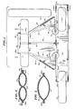
- Fig. 17 is a top plan view of the assembled device of Figs. 11-13 and 16 with a part of the crown portion thereof at the rear end cut away to better illustrate the structure and interconnection of the parts.
- Fig. 18 is a bottom view of the assembled completed device of Figs. ll-13, 16 and 17. (In the views of Figs. 17 and 18, the front is to the left in the views and the rear to the right in the views.)
- the psychological impact of chemotherapy-induced alopecia represents one of the more devastating side effects of cancer chemotherapy. In some instances, the psychological consequences of this leads patients to refuse potentially curative chemotherapy.
- the hair loss problem is severe with the anthracycline antibiotic Adriamycin (Doxorobicin) a chemotherapy compound which has a spectrum of efficacy encompassing many types of cancer (e.g., breast, lung and ovary sarcomas, lymphomas and leukemias).
- the Bean et al study involved the prophylactic treatment of cancer patients receiving adriamycin-cyclophosphamide combination chemotherapy with a brief scalp hypothermia procedure at the time of each injection.
- the particular procedure described used crushed ice and disposable plastics bags.
- This treatment proved to be simple, inexpensive, well tolerated and universally available. It further proved to be quite effective at preventing hair loss and the patients studied had good or excellent preservation of scalp hair, usually obviating the need of wigs for cosmetic purposes. An even higher portion of patients receiving chemotherapy doses of lesser strength had good protection.
- the protective scalp cooling was, to a certain extent, inversely related to dosage, so that a longer duration or more profound cooling might prove useful to consistently prevent hair loss at greater dosages.
- the noted scalp iceing procedure reduced Adriamycin-induced hair loss substantially in relation to extensive prior historical experience with that drug combination. Good protection against hair loss was frequently maintained for the full 6 to 8 months period of drug administration. In the article, it should be noted, it was also hypothesized that a longer initial cooling interval perhaps should be employed.
- the basic purpose of the present invention is to cool the scalp areas of chemotherapy patients (together with limited scalp zone constriction) in order to prevent hair loss in cancer chemotherapy.
- the construction and development is not limited to such use or mere cooling. Specifically, that is, the entire construction may alternatively be used as a scalp-heating cap, device or cover merely by substituting exothermic materials for the endothermic materials of a cooling application. In such use, the construction of application would be the same, however with heating produced rather than cooling.
- Refrigerating and heating packages of the type containing, within the outer pack, a dry chemical and a bag of watermixable therewith (on bursting of the water bag) to produce an endothermic or exothermic reaction, respectively, are well known to the art.
- U.S. patents nos. 2,925,719 and 3,643,665 typically show the state of the art with respect to such.
- the water may be isolated from a chemical before activation by means other than bagging.
- the prior art teaches chemical therapeutic packs which provide either reduced or increased temperatures by endothermic or exothermic chemical action, respectively.
- the components for such a reaction are both received within a plastics bag, separated from one another by an imperforate membrane.
- This membrane may be the outer bag itself crimped to divide the contents thereof or, alternatively and typically, the liquid component of the reaction (typically water) may be provided in a second imperforate bag received within the first bag.
- the bag containing the liquid may, in operation, be pressurized sufficiently to burst itself by manually squeezing the inner bag through the unpressurized outer bag.
- packs in accordance with the present invention may be employed to apply either cold or heat to the work object (the human head or a portion thereof) in the heat exchange, depending upon whether they contain chemical components for an endothermic or exothermic reaction, respectively.
- plastics films and laminate films (2) plastics film pouches, packages and containers and (3) heating or refrigerating package constructions of plastics film material.
- Typical materials making up such films include polyethylene, cellophane, polypropylene, polyester, etc.
- rupturable film packages and refrigerating packages the latter seen in the above-mentioned U.S. patent no. 2,925,719. Since polyethylene and polypropylene are heat sealable, they are also commonly used as the internal member of a film laminate in a package construction, with a polyester or cellophane layer comprising the external laminate layer. Laminate films seemingly seal better, and the seals last longer, than simple, non-laminate film.
- U.S. patent no. 2,925,719 discloses a refrigerating package including an outer envelope formed of a suitable, flexible, fluid tight, sheet plastics material (for example polyethylene, vinyl or acetate), an inner envelope formed of the same material, a quantity of dry refrigerating chemical such as ammonium nitrate within the outer envelope and a quantity of water or other hydrous chemical disposed within the inner envelope.
- a suitable, flexible, fluid tight, sheet plastics material for example polyethylene, vinyl or acetate
- a quantity of dry refrigerating chemical such as ammonium nitrate
- water or other hydrous chemical disposed within the inner envelope.
- U.S. patent no. 3,250,384 discloses (Figs. 7-9, inclusive) cooling packages of the type described and, as well, various materials useful in the films for the respective containers thereof. It should also be understood that double wall polyethylene bags or multiple layer polyethylene bags or containers may be employed, particularly for the outer bag, in said cold and heat packs, as seen in U.S. patents nos. 2,898,027 and 3,122,197, and, as well, U.S. method patents nos. 3,130,647 and 2,721,691.
- the device of the present invention may employ the heating and cooling packages of the type described whether (1) the chemicals in the bag are kept from one another by separate packaging or merely subdivision of the original package; (2) the outer container is single ply, multi-ply, a laminate of different materials, a plurality of plies of the same material or the like or (3) the inner container (if there is one) is single layered, multi-layered, multi-ply, laminate, weakened or the like.
- Polyethylene, polyvinyl and polymylar films of one or more layers or laminates may conveniently be employed in this inventory.
- a layer of non-allergenic paper may conveniently be laminated thereto for comfort, better skin sensation and condensation absorption (as an outside layer).
- Figs. 1-3 inclusive, therein is shown the blank for the human scalp heat exchanger before the cells of the blank are filled with heat-exchange materials for activation (preferably, water bags and ammonium nitrate, in the case of a cooling scalp heat exchanger).
- heat-exchange materials for activation preferably, water bags and ammonium nitrate, in the case of a cooling scalp heat exchanger.
- the walls of the blank and heat exchanger are laminates. That is, typically polyethylene or polypropylene on the inside with polyester or cellophane comprising the external laminate layer.
- each side wall of the portions of the blank or heat exchanger is a monolithic construction.
- an elongate rectangular headband portion generally designated 30, which has a lower edge 30a, an upper edge 30b, sealed first end edge 30c and open and unsealed end edge 30d.
- a three sided seal (conventionally an ultransonic weld or heat seal) for the elongate head band portion comprising, as mentioned, a double wall bag, each wall preferably a laminate of two films.
- the outer surface of the outside wall of headband portion 30 is numbered 31 and the inside wall numbered 32.
- a first elongate tab 33 having on its free outboard portion (Fig.
- an adhesive covering in the form of a removable sheet 34 At the other end on the outside surface of headband bag 30 is a tab 35, adhesively or otherwise attached to the outer surface 31, adapted to receive thereon the free end portion of tab 33 after removal of its adhesive cover for engaging purposes (and end abutment) with the end of the headband portion 30.
- a crown portion generally designated 36 has a rearward (in use) end or end edge 37, side edges 38 and 39 and a forward or front edge 40 which is integral with or secured to the centre of the upper edge of headband bag 30 with its own centre portion which is generally designated 41.
- two laminated sheets configured precisely to the configuration of the overall sheet of Fig. 1 may be laid in alignment with one another and heat sealed at the sides, ends and edges, as well as interiorly thereof, to one another to give the blank configuration being described.
- the seals may be heat seals, ultrasonic welds or other connections optimum to the plastics laminate sheets employed.
- the crown portion 36 had three main parts. The first of these comprises the two centre, forward cells 42 and 43 which are separated from one another and interiorly defined by seal 44. They are exteriorly defined by seals 45 and 46 and on the left side of Fig. 1 and 47 and 48 on the right hand side of Fig. 1. It is important to note that seals 46 and.48 run into and are continuous with the upper edge seal 30b of headband portion 30 so that there is a complete front end seal of compartments or cells 42 and 43.
- the second part of crown portion 36 is the rearward attachment flap, generally designated 49, having parallel side edges 38a and 39a running the length thereof as a continuation of edges and seals 38 and 39 and two feed or loading channels 42a and 43a which are defined between the side edge seals 38a and 39a and an extension 44a of seal 44 into flap 49.
- a seal tab 50 having removable adhesive cover sheets 50a (Fig. 4) on the inside thereof is adhesively or otherwise fixedly attached to the outside surface of rear attachment flap 49 of crown portion 36.
- the third part of the crown portion of the blank comprises the side grasping flaps 51 and 52 which are used by a patient in application as seen in Figs. 7 and 15. These flaps are completely isolated from cells 42 and 43 by seals 45-48, inclusive. Additionally, for convenience purposes in manufacture, seals 45 and 47 are continued as at 45a and 47a to the front edge 40 of crown portion 46.
- Fig. 1-3 inclusive comprises a multicelled, sealable blank defined by sealing together identical sheets of laminated plastics material configured in a certain manner, each of the cells or compartments having an open end or edge for filling. Yet additionally, for structural integrity and rigidity at a possible point of tear (inboard end edges of edge 40 of the crown portion), reinforcements 53 of C configuration are adhesively or otherwise connected to the forward end of the crown portion and the upper outer face of the headband portion.
- An optional diagonal seal, or two of them may be provided across the sealed end corners to reduce the internal capacity of the, headband portion and better confine the materials in the headband in the working skin contacting portion to be described.
- filling of the blank may take place.
- this typically involves, first, the insertion of one elongate water bag 54 into the open end edge 30 of the headband portion, the bag being pushed to the opposite end 30c.
- a quantity of heat exchanging chemical such as ammonium nitrate (55 in Fig. 4) is charged into the headband cell.
- a second water bag 56 is charged against the body of material and a heat seal 57 (Fig. 4) or other conventional type seal is employed to weld shut the entire cell of the headband portion 30.
- a charge of ammonium nitrate may be first inserted, then an elongate large size water bag, followed by a second charge of ammonium nitrate.
- the arrangement shown is that preferred from experience.
- the cells may be filled with repeatedly refrigerable gel-like compound of conventional type. This enables reusing of the scalp heat exchanger (insofar as is desirable).
- the device, with repeatedly refrigerable compound in the cells will work, certain hazards have been noted such as possible frostbite and excessive chilling if the temperature of chilling of the device is not precisely controlled.
- one or more diagonal seals may be employed or provided at the sealed ends of the headband portion to somewhat reduce the interior capacity of the headband portion in its overlap zone and better confine the materials in the inboard head contacting zone. Such are seen in dotted lines in the blank illustration of Fig. 1.
- the length of headband 30 may be substantially 29 1/2 inches (749.3mm) in blank, with its width 5 1/2 inches (139.7mm).
- the ' length of the crown section in blank, from seal 41 to rear edge 37, may be 14 1/2 inches (368.3mm).
- the width of crown rear end tab 49 may be 7 inches (177.8mm).
- the width of crown portion 36 at front edge 40 may be 19 inches (482.6mm).
- Tab 35 may be 9 inches (228.6mm) in length, with the free flap portion engageable therewith of flap 33 being 8 inches (203.2mm) in length.
- the free flap portions of adhesive flap 50 may be 5 inches (127mm) on each side of crown end portion 49.
- Typical quantities of water and ammonium nitrate in the headband portion 30 would be 650 grams of water in two 325 gram bag packages before a rupture and 650 grams of ammonium nitrate.
- a 225 gram water bag may be matched with 225 grams of ammonium nitrate.
- An alternative structure with close limitation of the cell volumes employs (1) in the headband portion 600 grams of NH4 N03, two 300 gram water bubbles and 60 grams binasal (thickener); (2) in the cap cells, each employs 200 grams NH4 N03 and 20 grams binasal.
- Binasal 81 is a coarse granulation, pregdatinized tapioca starch vended by A.E. Staley Mfg. Co. of Decatur, III. 62525.
- the device To apply the head piece or device to a patient, assuming the heat-exchanging medium is as illustrated (rupturable bags of liquid and dry mixing, exothermic or endothermic reacting chemical) the device first is activated. ⁇ Alternatively, if rerefrigerable fluid fills the cells, it must be refrigerated or heated to the proper temperature (depending upon whether the heat exchange is heating or cooling). For purposes of description (and, of course, the primary object of the device, specifically, use with chemotherapy patients), a cooling function will be assumed.
- the device may be laid down flat on the flat upper surface of a table in a manner of the illustration of Fig.4 (or with the device inverted from the underside of orientation shown). The operator then presses down on the water bags one by one, with the heel of one hand to activate (burst) them.
- the views of Figs. 7-10, inclusive and 14-16, inclusive show most of the basic steps in assembly and application of the activated device to the head of a chemotherapy patient. Reference is here again made to the specific description of the drawing figures made herebefore.
- the top or crown portion or section of the device is lifted up and placed on the top of the patient's head, with the wider front part 41 of the top section at the top of the patient's forehead, in order that the closed centre section of the headband portion will naturally fall down over or in front of the patient's forehead.
- the patient grasps the tabs 51 and 52 at the forward portion of the crown section just ahead of or opposite her ears, at the direction of the aide or helper, whose hands may be seen in the view grasping the end portions 30c, 30d of the headband.
- the patient pulls downwardly on tabs 51 and 52, seating the crown section, at least in the forward and central portions thereof, on the forward and central portions of her head.
- Fig. 8 shows a three quarter perspective view from the side and above of the left side of the device in the view of Fig. 7, illustrating the relative position of the parts as the aide pulls back the side sections of the headband to enclose the sides and temples of the patient's head. For simplicity, the head of the patient is not seen in Fig. 8.
- the aide overlaps ends 30c and 30d (specifically, 30c over 30d).
- Protective tab 33a is then (or before) stripped from the headband flap 33 and, closely adjusting the top edge of the headband against the side edges of the crown portion and exerting a mild or considerable (depending on what is decided for the specific patient) constrictive effort on the headband, the aide rather tightly secures the headband portion around the head of the patient..
- the headband portion is filled with liquid, which precisely adjusts at every point to the shape of the patient's head in the headband portion, under the constriction, a complete encirclement with continuous contact and mild or stronger constriction is relatively easily made.
- Fig. 8 shows the back end and rear tab portion 49 of crown section 36 angled upwardly, with attaching tab 50 raised above the headband portion which is being drawn back around the patient's head.
- Fig. 9 shows the headband encirclement completely made and the flap 33 firmly adhesively engaged over tab-surface 35.
- the helper first removes adhesive covering members 50a from the engaging flaps on end piece 49 and pulls down the rear flap or tab 49 of crown portion 36 over the rear outer surface of the secured headband. It is most important at this juncture that the operator or aide adjust the height of the headband and its position around . the head of the patient at the desired level front, sides and back. This includes essentially an entire forehead overlap, an ear overlap and the bottom part of the skull overlap at the rear.
- insulating sleeves may be slipped over the patient's ears to protect them from excessive chill, if needed or desired.
- Fig. 10 shows the near completed heat-exchanging device with the headband portion first tension (constriction) secured and the crown section thereafter secured thereto and thereover.
- the assemblage will now fall off the patient's head, but it is incomplete because (1) the side edges or walls of the top section heat-exchange bags have not been brought into complete abutment with the side top walls or edges of the headband cell in continuous contact and (2) the top cells of the crown section have not centrally been brought together in wall-to-wall contact to remove any possibility of a centre head holiday or noncooled area.
- Fig. 16 shows a view from the front of the patient with the completed heat-exchanging device on her head.
- the cap device now comprises a unit held together by (1) the headband to headband tab, (2) the crown section rear flap to headband tab and (3) the centre over the top adhesive band which is headband to crown cell, crown cell to crown cell and crown cell to headband.
- the unitary device may be adjusted to final precision and comfort for the user-wearer with full hair area contact, as well as full forehead contact, as clearly seen in Fig. 16.
- the heat-exchanging head piece of the present invention for cooling or heating the entire scalp (hair bearing) area of the human head, comprises, in combination:
- the entire headband portion 30 preferably comprises a single, continuous, elongate, rectangular hollow bag sealed continuously and circumferentially thereof at the side and end edges thereof. Headband portion 30 is most preferably longer than the circumference of the patient's head it is to encircle, so that the end edges 30c and 30d thereof abut and somewhat overlie one another when the headband portion is secured around the patient's head in use.
- the heat-exchanging materials 54-56 in'the headband portion preferably comprise two elongate, rectangular, water-containing bags 56 and 54 adapted to be pressure ruptured, (the bags, before activation, positioned one adjacent each end edge 30c, 30d of the headband portion 30) and dry chemical 55, such as ammonium nitrate, adapted to react with the water on rupture of the bags to provide an endothermic reaction.
- the means 33, 35 for securing the headband portion end edges 30c, 30d together preferably comprises an elongate flap having adhesive material on one side thereof for adhering to the outer walls of the headband portion free edges and ' areas of the headband next thereto and a tab 35 area secured to the outer surface of the headband adjacent one end to provide secure adhesive engagement with flap 33.
- the crown sections 36 of the heat-exchanging head piece is preferably divided into two elongate, hollow bags 42, 43 of sealed, watertight construction, the bags containing materials (58, 58a etc.) for heat exchange.
- Crown section 36 is preferably divided centrally into aligned, substantially equal size elongate bags 42, 43 of liquid tight construction running lengthwise substantially at right angles to the front edge connection 41 of the headband 30 and crown 36 portions.
- Substantially triangular tab portions 51 and 52 are preferably provided at each one of the side edges (45, 46 and 47, 48) of crown portion 36 adjacent the front edge connection 41 thereof.
- the means 50 at the rear edge 37 of crown portion 36 adapted to secure the crown portion rear end to a part of the headband portion preferably comprises a rearwardly- extending tab extension 49 of crown portion 36 adapted to overlie (outside of) and lie against the free end secured portion of the headband 30 (after the end edges 30c,30d of the same have been secured to one another) and be attached thereto.
- Tab extension 49 can underlie, but most preferably overlies, the secured headband end edge portion prior to engagement connection therewith.
- Adhesive flap 50 having adhesive material on the inboard side thereof, is adapted to secure the crown portion tab 49 on headband portions 30d and 30c (outside of the ends thereof after connection) together.
- the means 61 for securing the side upper edges of the headband portion to the side edges of the crown portion, whereby to form a continuous, scalp-connecting head piece preferably comprises at least one elongate strap'61 adhesively or otherwise engaged between the side edges of the headband portion and the side and top faces of the crown portion on each side of the head piece.
- the top side edges of the headband portion must be abutted against and essentially joined to the bottom side edge portions of the crown portion.
- This connection and adjustment can be made with only one elongate strap communicating from the side headband portion on one side to the opposite side headband portion over the crown, the strap secured to all three noted portions (opposed headband portions and crown).
- Two elongate straps of the character described, spaced apart from one another on the headpiece, may also secure the side edges of the headband at the upper portion thereof to the side edges of the crown at the side extremeities thereof to make an integral, uninterrupted head piece. The latter would be the case with an extremely long head structure or some other unusual size and/or head shape problem.
- liquid bag-ammonium nitrate or other dry chemical system a fluidic, repeatedly refrigerable chemical substance may fill the single cell of the headband portion and the two cells of the crown portion.
- the device preferably employs surfaces of non-allergenic sulphide paper laminating to polyethylene.
- the purpose of the use of such paper surfacing in hospital products is to minimize water condensation. Thus, condensation on the patient's head, and as well, the patient's hospital gown, any towels used or sheets when the patient is in bed, are minimized.
- the results found in the Beam et al article are, at the least, to be expected. At the very worst (under the most rigorous conditions of chemotherapy to a given patient, depending upon the patient's condition and the intensity and frequency of dosing) the device minimizes hair loss.
- the device may be made reuseable.
- This approach raises certain problems, including excessive chilling.
- hospitals do not prefer (necessarily, that is, depending upon the circumstances) reuseable devices. To some extent this may be because of convenience of billing procedures to the patient, but also, cleaning and cross-contamination problems, as well as storage, must be considered. Additionally, the provision of refrigeration devices reasonably adjacent to application points must be considered in this variation..
- the headband portion closed and continuous at the front, as well as a continuous cell for the headband.
- the headband portion With respect to the former, one wants full, continuous heat exchange of the forehead zone because of the numerous blood vessels passing therethrough.
- the second in the event or occasion of seams or breaks in continuity of the headband portion, because the headband portion is stretched to give constriction around the head, it would be extremely difficult, or well nigh impossible to avoid holidays or nonheat exchange zones. Accordingly, the continuity around the head: Since the headband must be open for application and adjustability purposes in its length, the cell making up the headband must be of sufficient length that it overlaps at the rear of the patient's head for continuity of heat exchange and cooling.
- the device of the invention has two or more head size adjustments.
- the first of these effected is the hat band or headband adjustment in the headband portion, per se. This is a complete circle of compression on all blood vessels leading into the scalp.
- the second adjustment is the crown size.
- These adjustments are effected sequentially, that is, the hat size is the first adjustment completely made and, thereafter, the crown size. If the cells of the device are not first activated (in the case of a one-shot type device), then the sequential adjustments could not be made, as well as the edge to edge adjustments at the seams.
- the headband portion at the rear of the head lie in the fact that the forehead is higher than the lower rear portion of the skull.
- the activated fluid in the headband cell when the securement is at the rear of the head at the base of the skull, tends to fill the entire cell, particularly at the base end.
- the fluid would tend to pool at the lower rear portion of the head and, additionally, there would be the hazard of the operator working in the vicinity of the patient's eyes.
- the .device of the invention is not useful in leukemia, because of the circulating cancer cells in the blood.
- the crown portion of the device For proper distribution of the activated liquid contents in the crown portion of the device, it is best that it be segmented into two cells. Such segmentation may be front to back 6r side to side and equally effective. However, the latter is harder.to fill and, additionally, . provide an integrated, easy to apply device. What is necessary in the crown portion is both confinement of fluids and distribution. Yet further, by manipulation of the pack as described in application, the cell abutment of one to another in the crown portion and with the headband cell is absolutely necessary for continuous cooling or heat-exchange surface and body.
- Ear covers of any simple construction and any insulating material, excluding polyethylene foam, may be advantageously used to minimize excess chilling or heating of a patient's temperature-sensitive ears. They are applied before application of the headband. None are shown in the views to minimize confusion between layers of material.
- a head piece in accordance with the invention is that cooling is supplied and effected for a sufficient time, to the proper degree and without excess cooling or freezing, in a most efficient and effective manner; there is some limitation of circulation into and out of the scalp area by mild constriction of this zone, or the periphery thereof (lower periphery including the forehead), the circulation limitation being adjustable in degree, provided in the proper position (approximate cap or hat headband area) and further being cushioned for comfort; the head piece may be applied to any individual's head, regardless of head size and/or shape, with reasonable ease of application requiring but a single helper, the ultimately-applied head piece being snug and comfortable on the user's head after application and easily and readily removable therefrom after performance of the chemotherapy injection; there is total area contact for heat exchange, specifically cooling, once the head piece is applied, such contact being without "holidays" which would result in hair loss, or possible hair loss if such were present, and full and continuous scalp contact being thus provided, both in the headband
Landscapes
- Health & Medical Sciences (AREA)
- Vascular Medicine (AREA)
- Thermal Sciences (AREA)
- Engineering & Computer Science (AREA)
- Biomedical Technology (AREA)
- Heart & Thoracic Surgery (AREA)
- Physics & Mathematics (AREA)
- Life Sciences & Earth Sciences (AREA)
- Animal Behavior & Ethology (AREA)
- General Health & Medical Sciences (AREA)
- Public Health (AREA)
- Veterinary Medicine (AREA)
- Thermotherapy And Cooling Therapy Devices (AREA)
Applications Claiming Priority (2)
| Application Number | Priority Date | Filing Date | Title |
|---|---|---|---|
| US06/199,738 US4382446A (en) | 1980-10-23 | 1980-10-23 | Heat transfer devices for the scalp |
| US199738 | 1980-10-23 |
Publications (2)
| Publication Number | Publication Date |
|---|---|
| EP0050948A2 true EP0050948A2 (de) | 1982-05-05 |
| EP0050948A3 EP0050948A3 (de) | 1982-09-08 |
Family
ID=22738805
Family Applications (1)
| Application Number | Title | Priority Date | Filing Date |
|---|---|---|---|
| EP81304841A Withdrawn EP0050948A3 (de) | 1980-10-23 | 1981-10-16 | Wärmeaustauschende Einrichtung für den Kopf |
Country Status (3)
| Country | Link |
|---|---|
| US (1) | US4382446A (de) |
| EP (1) | EP0050948A3 (de) |
| JP (1) | JPS5786340A (de) |
Cited By (3)
| Publication number | Priority date | Publication date | Assignee | Title |
|---|---|---|---|---|
| FR2536275A1 (fr) * | 1982-11-19 | 1984-05-25 | Sumitomo Rubber Ind | Equipement de refroidissement de tete |
| WO2017186965A1 (en) * | 2016-04-29 | 2017-11-02 | Recycold B.V. | Cooling element, its manufacture and its use |
| US11141309B2 (en) | 2019-06-03 | 2021-10-12 | Cooler Heads Care, Inc. | Cooling cap assembly and cooling unit |
Families Citing this family (64)
| Publication number | Priority date | Publication date | Assignee | Title |
|---|---|---|---|---|
| US4781193A (en) * | 1982-03-07 | 1988-11-01 | Pagden Kenneth L | Headache treatment apparatus |
| USD276651S (en) | 1982-03-31 | 1984-12-04 | Scholl, Inc. | Adjustable scalp hypothermia cap |
| US4765338A (en) * | 1982-12-29 | 1988-08-23 | Turner Richard W | Reuseable heat transfer devices for the scalp |
| JPS6036051A (ja) * | 1983-08-09 | 1985-02-25 | ニチバン株式会社 | 頭部の冷却具 |
| US4750493A (en) * | 1986-02-28 | 1988-06-14 | Brader Eric W | Method of preventing brain damage during cardiac arrest, CPR or severe shock |
| US4790042A (en) * | 1987-10-05 | 1988-12-13 | Reich Beth A | Baby comforter |
| US4922973A (en) * | 1988-11-17 | 1990-05-08 | Coil Matic, Inc. | Collecting vessels for collecting refrigerants from heat exchange systems and methods |
| US4972832A (en) * | 1989-11-15 | 1990-11-27 | Trapini Karen F | Thermal pack holder |
| US5662695A (en) * | 1990-09-05 | 1997-09-02 | Breg, Inc. | Occlusion-resistant fluid pad conformable to a body for therapeutic treatment thereof |
| US6277143B1 (en) | 1991-05-22 | 2001-08-21 | Life Science Holdings, Inc. | Brain cooling apparatus and method for cooling the brain |
| US5261399A (en) * | 1991-05-22 | 1993-11-16 | Klatz Ronald M | Brain cooling device and method for performing the same |
| US6030412A (en) * | 1991-05-22 | 2000-02-29 | Life Science Holdings, Inc. | Apparatus and method for cooling the brain, brain stem and associated neurologic tissues |
| US5265669A (en) * | 1991-06-13 | 1993-11-30 | Schneider Mark R | Tying neckband heat transfer device |
| US5088549A (en) * | 1991-06-13 | 1992-02-18 | Warren Locke Franz | Tying neckband heat transfer device |
| US5800492A (en) * | 1992-01-23 | 1998-09-01 | Prism Enterprises, Inc. | Adhesive warming bag |
| US5314456A (en) * | 1993-03-19 | 1994-05-24 | Cohen Gary M | Therapeutic pad for relief of headache-related head, temple, neck and back pain |
| US5470353A (en) * | 1993-10-20 | 1995-11-28 | Hollister Incorporated | Post-operative thermal blanket |
| US5411542A (en) * | 1993-10-20 | 1995-05-02 | Hollister Incorporated | Post-operative thermal blanket for ankle and foot |
| US5480418A (en) * | 1994-03-11 | 1996-01-02 | Zeoli-Jones; Alyce | Thermal transfer hair treatment cap |
| US6117164A (en) * | 1997-06-06 | 2000-09-12 | Dj Orthopedics, Llc | Flexible multijoint therapeutic pads |
| US5897582A (en) * | 1997-11-13 | 1999-04-27 | Agnatovech; Stephen | Migraine relief pressure cap |
| JP4010662B2 (ja) * | 1998-08-11 | 2007-11-21 | 花王株式会社 | 加温具及びその製造方法 |
| US6524331B1 (en) | 1998-09-18 | 2003-02-25 | Allegiance Corporation | Thermal device with automatic nesting feature |
| US7785359B2 (en) * | 1998-12-18 | 2010-08-31 | Traumatec, Inc. | Therapeutic cooling devices |
| US6183501B1 (en) | 1998-12-18 | 2001-02-06 | Jeffrey W. Latham | Head and spine cooling device |
| ES2206252T3 (es) * | 1999-06-11 | 2004-05-16 | Koninklijke Philips Electronics N.V. | Sistema de depilacion con dispositivo depilador y dispositivo de refrigeracion que tiene ciertos parametros. |
| US7028687B1 (en) | 1999-08-26 | 2006-04-18 | Precious Life, Llc | Escape hood |
| US6554787B1 (en) | 1999-08-30 | 2003-04-29 | Brand N. Griffin | Headband for treatment of headaches |
| US6182294B1 (en) * | 2000-06-20 | 2001-02-06 | Debra Pulley | Head covering with heat generating means |
| US6560784B2 (en) * | 2001-02-05 | 2003-05-13 | Jordan Heather Meredith Hill | Multi-layered moisture resistant hair wrap |
| FR2821250B1 (fr) * | 2001-02-28 | 2006-02-03 | Kao Corp | Dispositif pour chauffer les cheveux et procede de traitement capillaire utilisant ce dispositif |
| US20040064169A1 (en) * | 2002-09-30 | 2004-04-01 | Briscoe Kathleen E. | User interface for medical device |
| US7179279B2 (en) * | 2002-09-30 | 2007-02-20 | Medtronic Physio Control Corp. | Rapid induction of mild hypothermia |
| US7087075B2 (en) * | 2002-09-30 | 2006-08-08 | Medtronic Emergency Response Systems, Inc. | Feedback system for rapid induction of mild hypothermia |
| US8226698B2 (en) * | 2002-10-08 | 2012-07-24 | Vitalwear, Inc. | Therapeutic cranial wrap for a contrast therapy system |
| US7056282B2 (en) * | 2002-12-23 | 2006-06-06 | Medtronic Emergency Response Systems, Inc. | Coolant control for rapid induction of mild hypothermia |
| US20040138729A1 (en) * | 2003-01-10 | 2004-07-15 | Andrea Ladmer | Head area heat exchange apparel and system |
| US20050027173A1 (en) * | 2003-07-31 | 2005-02-03 | Briscoe Kathleen E. | Brain injury protocols |
| US20050042267A1 (en) * | 2003-08-20 | 2005-02-24 | Kimberly-Clark Worldwide, Inc. | System for providing therapy to a portion of a body |
| US6918138B2 (en) * | 2003-09-05 | 2005-07-19 | James A. Donovan | Heated shower cap |
| US6893455B1 (en) | 2003-12-10 | 2005-05-17 | Sharon R. Rafferty | Cooling band |
| US20060064148A1 (en) * | 2004-09-23 | 2006-03-23 | Sammarco Domenic A | Self-adherent instant cold compress therapeutic wrap |
| US20060067994A1 (en) * | 2004-09-30 | 2006-03-30 | Kimberly-Clark Worldwide, Inc. | System for providing therapy to a body |
| US7306332B2 (en) * | 2005-08-30 | 2007-12-11 | Chien Pong Chen | Eyewear temple assembly |
| US8641660B2 (en) * | 2006-10-04 | 2014-02-04 | P Tech, Llc | Methods and devices for controlling biologic microenvironments |
| GB2457077A (en) * | 2008-02-01 | 2009-08-05 | Julian Joshua Preston-Powers | Cooling system for headwear |
| GB0913561D0 (en) * | 2009-08-04 | 2009-09-16 | Gilholm Harrison Ltd | Brain cooling device |
| US11980246B1 (en) * | 2009-12-30 | 2024-05-14 | Equalizer Technology LLC | Care giver display surgical cap to control patient body temperature |
| US12226230B1 (en) * | 2009-12-30 | 2025-02-18 | David G. Abood | Care giver display surgical cap to control patient body temperature |
| US11545052B1 (en) * | 2009-12-30 | 2023-01-03 | Equalizer Technology LLC | Insulative rescue cap containing emergency response procedures |
| US8418269B1 (en) * | 2010-08-05 | 2013-04-16 | William B. McBride | Protective head having impact force distribution |
| WO2012028730A1 (en) | 2010-09-02 | 2012-03-08 | Thermather Sarl | Device for thermal treatment of the scalp |
| US20120253384A1 (en) * | 2011-03-29 | 2012-10-04 | Cynthia Lee Bosnyak | Nicy migraine hugger |
| US20130041439A1 (en) * | 2011-08-12 | 2013-02-14 | James Joseph Gallagher | Cold cap |
| US10226378B2 (en) * | 2013-02-28 | 2019-03-12 | Carmen Schuller | Disposable thermal regulation apparatus |
| US11357665B2 (en) | 2013-03-13 | 2022-06-14 | Jeffrey Foster | Cerebral protection system |
| US10076440B2 (en) * | 2013-03-13 | 2018-09-18 | University Hospital Of Cleveland | Cerebral protection system |
| US20140379058A1 (en) * | 2013-06-24 | 2014-12-25 | Ampac Enterprises Inc. | Apparatus and Method for Cooling Head Injury |
| US9615968B2 (en) * | 2014-04-16 | 2017-04-11 | David Rand | Portable rapid cooling, hypothermia inducing headgear apparatus for tissue preservation |
| US10806626B2 (en) | 2015-02-04 | 2020-10-20 | Michael Lynn Zumbrunnen | Method and apparatus of a self-managed portable hypothermia system |
| US20160367396A1 (en) * | 2015-06-18 | 2016-12-22 | Oronzo Triggiano | Cold cap |
| US20170296381A1 (en) * | 2016-04-14 | 2017-10-19 | Paul Fox | Sportswear cooling system |
| CN113423367A (zh) | 2018-11-09 | 2021-09-21 | 迪格尼塔纳公司 | 头皮冷却装置、方法和系统 |
| US11278447B2 (en) | 2019-09-25 | 2022-03-22 | David Rand | Portable thermal therapy and support apparatus for emergency medical treatment |
Family Cites Families (13)
| Publication number | Priority date | Publication date | Assignee | Title |
|---|---|---|---|---|
| US1569877A (en) * | 1924-07-03 | 1926-01-19 | Owens Samuel Logan | Apparatus for maintaining constant temperature on a portion of the body |
| US1870143A (en) * | 1929-11-05 | 1932-08-02 | Grace E Roux | Ice bag |
| US1964655A (en) * | 1932-03-22 | 1934-06-26 | Williamson Estelle | Ice bag |
| US2726658A (en) * | 1953-04-27 | 1955-12-13 | Donald E Chessey | Therapeutic cooling devices for domestic and hospital use |
| US3149943A (en) * | 1961-11-20 | 1964-09-22 | Martin R Amador | Chemical refrigerant package |
| US3491761A (en) * | 1966-10-10 | 1970-01-27 | Marjorie M Baker | Adjustable ice bag harness |
| US3717145A (en) * | 1971-05-03 | 1973-02-20 | W Berndt | Cold pressure bandage |
| US4055188A (en) * | 1976-02-09 | 1977-10-25 | Divajex | Therapeutic wrap |
| US4061898A (en) * | 1976-08-16 | 1977-12-06 | Redken Laboratories, Inc. | Heat cap |
| US4190054A (en) * | 1977-12-14 | 1980-02-26 | Brennan H George | Therapeutic bandage with removable hot or cold packs |
| US4204543A (en) * | 1978-01-06 | 1980-05-27 | Henderson Mary M | Coolant band |
| DE2948059A1 (de) * | 1979-11-29 | 1981-07-30 | Vasile Dr.med. 6750 Kaiserslautern Tataru | Vorrichtung zur zeitweisen unterbrechung der arteriellen durchblutung am hautschaedel |
| DE8115207U1 (de) * | 1981-05-21 | 1981-09-17 | Hospipharm AG, Ergerta | "Zur therapeutischen Behandlung der Kopfhaut mit Kälte vorgesehene flexible Kompresse" |
-
1980
- 1980-10-23 US US06/199,738 patent/US4382446A/en not_active Expired - Lifetime
-
1981
- 1981-09-24 JP JP56151302A patent/JPS5786340A/ja active Granted
- 1981-10-16 EP EP81304841A patent/EP0050948A3/de not_active Withdrawn
Cited By (4)
| Publication number | Priority date | Publication date | Assignee | Title |
|---|---|---|---|---|
| FR2536275A1 (fr) * | 1982-11-19 | 1984-05-25 | Sumitomo Rubber Ind | Equipement de refroidissement de tete |
| WO2017186965A1 (en) * | 2016-04-29 | 2017-11-02 | Recycold B.V. | Cooling element, its manufacture and its use |
| US11141309B2 (en) | 2019-06-03 | 2021-10-12 | Cooler Heads Care, Inc. | Cooling cap assembly and cooling unit |
| US11622881B2 (en) | 2019-06-03 | 2023-04-11 | Cooler Heads Care, Inc. | Cooling cap assembly and cooling unit |
Also Published As
| Publication number | Publication date |
|---|---|
| EP0050948A3 (de) | 1982-09-08 |
| US4382446A (en) | 1983-05-10 |
| JPS5786340A (en) | 1982-05-29 |
| JPS6129739B2 (de) | 1986-07-09 |
Similar Documents
| Publication | Publication Date | Title |
|---|---|---|
| US4382446A (en) | Heat transfer devices for the scalp | |
| US4765338A (en) | Reuseable heat transfer devices for the scalp | |
| US5129391A (en) | Thermal packs | |
| EP0613357B1 (de) | Thermalbandage | |
| US5456704A (en) | Method of treatment with therapeutic moist heating pad | |
| US6083256A (en) | NNT or cold pad with inner element | |
| US6524331B1 (en) | Thermal device with automatic nesting feature | |
| US3717145A (en) | Cold pressure bandage | |
| US5277180A (en) | Absorbent pad and thermal pack | |
| US5184613A (en) | Thermal pack heel warming apparatus for a neonate or infant | |
| US4243041A (en) | Cold-pack goggles | |
| US8696726B2 (en) | Flexible closed flat pad for cooling a body part | |
| US7784304B2 (en) | Non-slip ice bag device and method for using same to treat patients | |
| JP4887382B2 (ja) | 温度調節パウチパック | |
| US6602213B1 (en) | Disposable splint with instant cold pack | |
| MXPA03003134A (es) | Despachador de producto que tiene un elemento interno para cambiar la temperatura. | |
| EP3797741B1 (de) | Tragbare thermische therapie- und unterstützungsvorrichtung für medizinische notfallbehandlung | |
| US20140128945A1 (en) | Noninvasive cooling device | |
| US5062425A (en) | Expansible internal pressure cold packs and perineal ice pad | |
| US4522640A (en) | Means for chilling cardioplegic solutions | |
| US5791334A (en) | Heat pack resistant to saddle-bagging | |
| JP2019514637A (ja) | 冷却機能を有する材料を備える物品 | |
| US4354496A (en) | Hood for prevention of scalp hair loss | |
| JP3011891B2 (ja) | 加熱保温容器、加熱保温装置付きウエットティッシュ包装体、加温材及び吸水性部材 | |
| US6500199B1 (en) | Enclosure bag for maintaining a patient's body temperature during surgical procedures |
Legal Events
| Date | Code | Title | Description |
|---|---|---|---|
| PUAI | Public reference made under article 153(3) epc to a published international application that has entered the european phase |
Free format text: ORIGINAL CODE: 0009012 |
|
| AK | Designated contracting states |
Designated state(s): DE FR GB IT SE |
|
| PUAL | Search report despatched |
Free format text: ORIGINAL CODE: 0009013 |
|
| AK | Designated contracting states |
Designated state(s): DE FR GB IT SE |
|
| 17P | Request for examination filed |
Effective date: 19830223 |
|
| STAA | Information on the status of an ep patent application or granted ep patent |
Free format text: STATUS: THE APPLICATION HAS BEEN WITHDRAWN |
|
| 18W | Application withdrawn |
Withdrawal date: 19851004 |
|
| RIN1 | Information on inventor provided before grant (corrected) |
Inventor name: TRUELOCK, DONALD E. Inventor name: TURNER, RICHARD W. |