EP0050959B1 - Schmiersystem für eine Kraftanlage mit einem organischen Fluidum - Google Patents
Schmiersystem für eine Kraftanlage mit einem organischen Fluidum Download PDFInfo
- Publication number
- EP0050959B1 EP0050959B1 EP81304947A EP81304947A EP0050959B1 EP 0050959 B1 EP0050959 B1 EP 0050959B1 EP 81304947 A EP81304947 A EP 81304947A EP 81304947 A EP81304947 A EP 81304947A EP 0050959 B1 EP0050959 B1 EP 0050959B1
- Authority
- EP
- European Patent Office
- Prior art keywords
- condensate
- power plant
- bearings
- working fluid
- canister
- Prior art date
- Legal status (The legal status is an assumption and is not a legal conclusion. Google has not performed a legal analysis and makes no representation as to the accuracy of the status listed.)
- Expired
Links
Images
Classifications
-
- F—MECHANICAL ENGINEERING; LIGHTING; HEATING; WEAPONS; BLASTING
- F01—MACHINES OR ENGINES IN GENERAL; ENGINE PLANTS IN GENERAL; STEAM ENGINES
- F01K—STEAM ENGINE PLANTS; STEAM ACCUMULATORS; ENGINE PLANTS NOT OTHERWISE PROVIDED FOR; ENGINES USING SPECIAL WORKING FLUIDS OR CYCLES
- F01K25/00—Plants or engines characterised by use of special working fluids, not otherwise provided for; Plants operating in closed cycles and not otherwise provided for
-
- F—MECHANICAL ENGINEERING; LIGHTING; HEATING; WEAPONS; BLASTING
- F01—MACHINES OR ENGINES IN GENERAL; ENGINE PLANTS IN GENERAL; STEAM ENGINES
- F01K—STEAM ENGINE PLANTS; STEAM ACCUMULATORS; ENGINE PLANTS NOT OTHERWISE PROVIDED FOR; ENGINES USING SPECIAL WORKING FLUIDS OR CYCLES
- F01K7/00—Steam engine plants characterised by the use of specific types of engine; Plants or engines characterised by their use of special steam systems, cycles or processes; Control means specially adapted for such systems, cycles or processes; Use of withdrawn or exhaust steam for feed-water heating
- F01K7/16—Steam engine plants characterised by the use of specific types of engine; Plants or engines characterised by their use of special steam systems, cycles or processes; Control means specially adapted for such systems, cycles or processes; Use of withdrawn or exhaust steam for feed-water heating the engines being only of turbine type
-
- F—MECHANICAL ENGINEERING; LIGHTING; HEATING; WEAPONS; BLASTING
- F01—MACHINES OR ENGINES IN GENERAL; ENGINE PLANTS IN GENERAL; STEAM ENGINES
- F01D—NON-POSITIVE DISPLACEMENT MACHINES OR ENGINES, e.g. STEAM TURBINES
- F01D25/00—Component parts, details, or accessories, not provided for in, or of interest apart from, other groups
- F01D25/18—Lubricating arrangements
- F01D25/22—Lubricating arrangements using working-fluid or other gaseous fluid as lubricant
-
- F—MECHANICAL ENGINEERING; LIGHTING; HEATING; WEAPONS; BLASTING
- F16—ENGINEERING ELEMENTS AND UNITS; GENERAL MEASURES FOR PRODUCING AND MAINTAINING EFFECTIVE FUNCTIONING OF MACHINES OR INSTALLATIONS; THERMAL INSULATION IN GENERAL
- F16N—LUBRICATING
- F16N39/00—Arrangements for conditioning of lubricants in the lubricating system
- F16N39/02—Arrangements for conditioning of lubricants in the lubricating system by cooling
Definitions
- This invention relates to an improved lubricating system for an organic fluid power plant wherein the working fluid lubricates the bearings of the prime mover of the power plant.
- GB-A-1134391 discloses a water lubricating system for a steam turbine driven impeller pump including a lubricating water storage tank comprising a top compartment and bottom compartment, and a one-way valve for gravity feeding water from the top to the bottom compartment. Steam leaking from the bearings of the pump is directed into the top compartment where condensation and heating of the water in the compartment takes place. An overflow valve maintains a limit on the height of the water in the top compartment. Water that leaks from the bearings is returned to the bottom compartment which is also supplied with make-up water controlled by a float valve for establishing a minimum and maximum level in the bottom compartment. Water drawn from the bottom compartment, is cooled to extract heat added to the water by reason of the steam that leaks from the bearings and is inputted into the top compartment, is applied to the bearings for lubrication purposes.
- a closed, Rankine cycle power plant is disclosed in US-A-3,393,515 wherein an organic working fluid is vaporized in a boiler and supplied to a turbine which, together with a generator, is mounted on a common shaft rotatably supported on hydrodynamic bearings in an hermetically sealed canister. Vapour exhausted from the turbine is passed into a condenser which converts the exhaust vapour into condensate at a lower temperature and pressure than in the boiler. Some of the condensate in the condenser is supplied to the bearings, and the remainder is returned to the boiler, either directly, if the condenser is elevated sufficiently relative to the boiler, or via a pump if the elevation is insufficient.
- a power plant is hereinafter termed a power plant of the type described.
- hydrodynamically lubricated bearings in a power plant of the type described ensures the presence of a fluid film of lubricant between the metal of the journal and the metal of the bearings. As a consequence, the only friction is that which occurs in the fluid film as it is sheared due to rotation of the journal.
- the bearings By utilizing techniques that ensure a supply of liquid working fluid to the bearings prior to start-up of the turbine or a power plant of the type described and by utilizing an hermetically sealed canister, the bearings will always be lubricated adequately, and their life will be indeterminately long with the result that a highly reliable power plant is established.
- power plants of the type described have heretofore been limited almost exclusively to relatively low levels of power, typically 1-2 KW.
- a power plant of the type described is well adapted, and is currently being utilized successfully, for powering unmanned microwave relay stations located in remote regions of the world, wherein the only maintenance over extended periods of time is replenishment of the fuel for the boiler.
- the mass flow required to produce such relatively low levels of power can be handled well by a partial admission nozzle system which provides a turbine of relatively small size with a rotational speed that permits the turbine to be coupled directly to the generator.
- the turbine wheel and generator can be mounted on a common shaft.
- the temperature of the condensate may be as high as 66°C
- the viscosity of the working fluid which may be Freon 12 or a similar organic fluid, is such that the resultant minimum lubricating film thickness formed by the condensate in the bearing is large enough under the conditions of rotational speed and bearing load for conventional metal working techniques to be utilized in fabricating the bearings and journals.
- the diameter of the turbine must be increased significantly to provide sufficient cross-sectional area for the nozzles to achieve the required through-put of working fluid.
- the rotor speed must be reduced to maintain rotor stress within allowable limits. For example, a 1-2 KW power plant will operate at around 12,000 RPM while a turbine in the 500 KW range will operate at around one- fourth of this speed. Consequently, a direct coupling between the turbine and rotor can no longer be utilized. Instead, an indirect mechanical coupling, such as a gear train, must be interposed between the turbine and the generator. This requirement creates a number of problems.
- the viscosity of a typical organic working fluid at the condenser temperature is so low that liquid working fluid cannot adequately lubricate the rubbing surfaces of the mating gears. Therefore it is conventional to place both the gearbox and the generator outside the turbine canister. This means that the turbine shaft must pass through the canister, thus reducing the quality of the hermetic seal of the canister. At best, long term operation will result in the loss of working fluid at the rotary seal through which the turbine output shaft passes, and/or contamination of the working fluid from environmental factors.
- the advantage of this approach is that conventional lubricants can be used in the gear box. As a consequence, power plants in the range 150-500 KW have been built and operated successfully by placing the gear box and generator outside the canister containing the turbine.
- the present invention provides for increasing the viscosity of the condensate used to lubricate the bearings to a level greater than the viscosity of the condensate returned to the boiler.
- the viscosity of the lubricant condensate is increased by cooling such condensate to a temperature below the temperature of the condenser.
- By significantly decreasing the temperature of the lubricating condensate its viscosity can be greatly increased with the result that the minimum thickness of the lubricating film in the bearings is increased significantly thereby reducing filtering demands on the lubricating condensate and permitting the journals and bearings to be finished by standard precision grinding techniques.
- the canister has a sump for collecting liquid working fluid which is delivered to the bearings through a cooler.
- the prime mover is coupled to a generator through a gearbox, all of which are contained in the sealed canister, the viscosity of the condensate may be increased to such a level that the cooled working fluid is adequate to lubricate the gearbox itself.
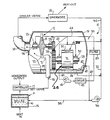
- a power plant 10 comprising three main components, namely a boiler 11, a prime mover 12 in the form of a turbine 13, and a condenser 14 operatively connected together.
- the boiler 11 comprises a metallic shell 15 containing a liquid working fluid 16 to which heat is supplied by a burner (not shown) for the purpose of converting the liquid working fluid in the boiler into vapour.
- Hot vapour is supplied, via a controller 17, to an intake pipe 18 connected to a canister 19 which houses a prime mover.
- the turbine wheel is rigidly attached to a shaft 23 carrying journals 24 at its opposite ends, the journals being housed within bearings 25 for the purpose of rotatably supporting the shaft 23 within the canister.
- the hot vapour from the boiler expands in the nozzle configuration 21; and the resultant high velocity vapour impinges on the blades 22 of the turbine to drive the latter and the generator.
- the exhaust vapour which leaves the blades passes into an exhaust conduit 33 which conducts the cooled vapour to the condenser 14.
- the condenser removes heat from the exhaust vapour which is converted into a liquid at a temperature and pressure considerably below the temperature and pressure in boiler 11.
- the boiler pressure typically, will be about 8.95 bar at a temperature of about 104°C.
- the condenser pressure will be about 2.41 bar at a temperature of about 50°C.
- the entire canister is filled with vapour at the condenser temperature and pressure, and any condensate formed in the canister collects in the sump 39 at the lowermost level of the canister.
- the condensate in the sump 39 will be at substantially the condenser temperature and is drawn off via a line 40 by a pump 41 which pumps the liquid through a cooler 42 where the temperature of the liquid, and as a consequence its viscosity, is substantially reduced.
- the temperature of the working fluid may be reduced from about 44°C entering the cooler to about -15°C at the exit.
- the cooled working fluid then passes through a filter 43 and is delivered to a piping arrangement 44 which conducts the cooled liquid to bearings 25 and 30 as well as to a dripper line 45 which supplies cooled liquid working fluid to the meshing teeth of the gear train 27, 28.
- Liquid drained from the bearings 25 and 30, and drained liquid from the lubrication of the gear train 27, 28 are collected in the sump 39 to complete the cycle for the bearing lubrication system 35.
- a valve with a float 46 has a needle 47 which is operatively associated with a valve seat 48 connected to one branch of the outlet of the pump 36.
- the float 46 rises and falls as the level in the sump 39 rises and falls thereby selectively opening and closing the valve and maintaining the level of liquid in the sump at a predetermined value sufficient for the pump 41 to supply liquid working fluid to the bearings and the gear train.
- Liquid from the sump is normally drained through a check valve (not shown) via a line 49 which is connected to the inlet of the pump 36.
- the bearing lubrication system would be substantially as shown in the drawing except that the cooler 42 would be absent and the pump 41 would return sump liquid to the boiler.
- the advantages gained by reason of the presence of the cooler 42 can best be understood by specific examples of the minimum lubricating film thickness in the turbine bearings when a conventional lubrication system is used, and when the cooler 42 is used according to the present invention. Assuming a 300 KW turbine and a working fluid of Freon 11, and the temperatures and pressures in the boiler and condenser indicated previously, a typical turbine rotor will weigh approximately 100 kg and will rotate at about 3,000 RPM. Good bearing design would necessitate a journal about 100 mm in length and about 50 mm in diameter.
- the minimum lubricating film thickness hmin can be computed.
- the latter has the value 0.002 mm which is so small that excellent bearing surfaces are required and the liquid working fluid must be unusually clean in order to prevent scoring. Such a small minimum film thickness is impractical because of the surface finish constraints imposed by such thickness.
- the cooler 42 which lowers the temperature of the lubricating fluid, its viscosity can be doubled.
- the viscosity of the working fluid is approximately 0.3 cp while at -15°C, the viscosity is about 0.63 cp.
- the Sommerfeld number associated with the bearing is approximately doubled by the provision of cooler 42.
- the minimum film thickness of the lubricating liquid in the bearing will be approximately 0.0065 mm which is nearly a three-fold improvement in minimum film thickness by reason of supercooling in the liquid working fluid.
- liquid working fluid at the condenser temperature in the conduit 34 permits a portion of the condensate to be diverted to the stator windings 32 of the generator for the purpose of cooling the windings and reducing the amount of copper needed. Consequently, the drawing shows a liquid working fluid being conducted to the stator via a line 50.
- the boiler temperature would be about 90°C at a pressure of 3.45 bar.
- a typical condenser would be at 35°C producing a back-pressure of about .69 bar.
- the turbine speed would be about 12000 RPM and the journal load would be about 12 lbs.
- the viscosity of R 114 B2 is about 0.65 cp while at 10°C, it is approximately doubled (1.2 cp).
- the Sommerfeld number for the bearing is about 4.72. With an eccentricity ratio of 0.38, the minimum lubricating film thickness is about 0.0079 mm.
- the effective bearing temperature will be approximately 1.7°C. This provides a Sommerfeld number of about 5.3 and will result in minimum lubricating thickness of approximately 0.010 mm which is 20% greater than in the case where the working fluid is not cooled.
- the boiler temperature would be about 90°C at a pressure of 3.45 bar.
- a typical condenser would be at 35°C producing a back-pressure of about .69 bar.
- the turbine speed would be about 12000 RPM and the journal load would be about 2.72 kg.
- the viscosity of F-113 is about 0.59 cp while at -15°C, it is approximately doubled (1.28 cp).
- the Sommerfeld number for the bearing is about 0.11. This value, when corrected for temperature and end losses is reduced to 0.022.
- the minimum lubricating film thickness is about .0076 mm.
- machining tolerances are increased by about 40%; and at the same time, the working conditions of the bearing are improved by increasing the minimum film thickness and lowering the eccentricity. Additionally, the increase in clearance dimensions beneficially influences the whirl behaviour of the bearing.
Landscapes
- Engineering & Computer Science (AREA)
- General Engineering & Computer Science (AREA)
- Mechanical Engineering (AREA)
- Chemical & Material Sciences (AREA)
- Combustion & Propulsion (AREA)
- Sliding-Contact Bearings (AREA)
- Engine Equipment That Uses Special Cycles (AREA)
- Motor Or Generator Cooling System (AREA)
- Connection Of Motors, Electrical Generators, Mechanical Devices, And The Like (AREA)
Claims (7)
Applications Claiming Priority (2)
| Application Number | Priority Date | Filing Date | Title |
|---|---|---|---|
| US199841 | 1980-10-23 | ||
| US06/199,841 US4363216A (en) | 1980-10-23 | 1980-10-23 | Lubricating system for organic fluid power plant |
Publications (2)
| Publication Number | Publication Date |
|---|---|
| EP0050959A1 EP0050959A1 (de) | 1982-05-05 |
| EP0050959B1 true EP0050959B1 (de) | 1986-06-11 |
Family
ID=22739242
Family Applications (1)
| Application Number | Title | Priority Date | Filing Date |
|---|---|---|---|
| EP81304947A Expired EP0050959B1 (de) | 1980-10-23 | 1981-10-21 | Schmiersystem für eine Kraftanlage mit einem organischen Fluidum |
Country Status (10)
| Country | Link |
|---|---|
| US (1) | US4363216A (de) |
| EP (1) | EP0050959B1 (de) |
| JP (1) | JPS57105509A (de) |
| KR (1) | KR890000916B1 (de) |
| AR (1) | AR229166A1 (de) |
| AU (1) | AU7638481A (de) |
| BR (1) | BR8106782A (de) |
| DE (1) | DE3174817D1 (de) |
| MX (1) | MX154541A (de) |
| PH (1) | PH20073A (de) |
Cited By (7)
| Publication number | Priority date | Publication date | Assignee | Title |
|---|---|---|---|---|
| US6880344B2 (en) | 2002-11-13 | 2005-04-19 | Utc Power, Llc | Combined rankine and vapor compression cycles |
| US6892522B2 (en) | 2002-11-13 | 2005-05-17 | Carrier Corporation | Combined rankine and vapor compression cycles |
| US6962056B2 (en) | 2002-11-13 | 2005-11-08 | Carrier Corporation | Combined rankine and vapor compression cycles |
| US7146813B2 (en) | 2002-11-13 | 2006-12-12 | Utc Power, Llc | Power generation with a centrifugal compressor |
| US7174716B2 (en) | 2002-11-13 | 2007-02-13 | Utc Power Llc | Organic rankine cycle waste heat applications |
| US7254949B2 (en) | 2002-11-13 | 2007-08-14 | Utc Power Corporation | Turbine with vaned nozzles |
| US7281379B2 (en) | 2002-11-13 | 2007-10-16 | Utc Power Corporation | Dual-use radial turbomachine |
Families Citing this family (39)
| Publication number | Priority date | Publication date | Assignee | Title |
|---|---|---|---|---|
| JPS5951109A (ja) * | 1982-09-17 | 1984-03-24 | Hitachi Ltd | 蒸気原動所の復水器真空保持装置 |
| WO1987007360A1 (fr) * | 1986-05-19 | 1987-12-03 | Yamato Kosan Co., Ltd. | Systeme echangeur de chaleur |
| US5066197A (en) * | 1990-07-10 | 1991-11-19 | Sundstrand Corporation | Hydrodynamic bearing protection system and method |
| FI86464C (fi) * | 1990-09-26 | 1992-08-25 | High Speed Tech Ltd Oy | Foerfarande foer att saekra lagersmoerjning i en hermetisk hoegshastighetsmaskin. |
| US5636708A (en) * | 1994-05-16 | 1997-06-10 | Wedeven; Lavern D. | Method and device for broad temperature range vapor lubrication |
| US5584360A (en) * | 1994-05-16 | 1996-12-17 | Wedeven; Lavern D. | Method for broad temperature range lubrication with vapors |
| WO2001031229A2 (en) * | 1999-10-25 | 2001-05-03 | Rolls-Royce Corporation | Method and apparatus for adjusting lubricant temperature within a gearbox |
| US6494042B2 (en) * | 2001-02-12 | 2002-12-17 | Ormat Industries Ltd. | Method of and apparatus for producing uninterruptible power |
| US6981378B2 (en) * | 2001-02-12 | 2006-01-03 | Ormat Technologies Inc. | Method of and apparatus for producing uninterruptible power |
| JP2003097212A (ja) | 2001-09-21 | 2003-04-03 | Honda Motor Co Ltd | 回転流体機械 |
| JP4286062B2 (ja) * | 2003-05-29 | 2009-06-24 | 株式会社荏原製作所 | 発電装置および発電方法 |
| WO2005021936A2 (en) * | 2003-08-27 | 2005-03-10 | Ttl Dynamics Ltd | Energy recovery system |
| JP4725344B2 (ja) * | 2005-04-26 | 2011-07-13 | 株式会社日本自動車部品総合研究所 | 流体機械および蒸気圧縮式冷凍機 |
| US7870733B2 (en) | 2005-12-21 | 2011-01-18 | Denso Corporation | Fluid machine for rankine cycle |
| WO2007136938A2 (en) * | 2006-04-07 | 2007-11-29 | Cooper Benjamin J | An efficient power turbine and electrical generation system |
| JP4913904B2 (ja) * | 2007-07-27 | 2012-04-11 | ユナイテッド テクノロジーズ コーポレイション | 有機ランキンサイクル(orc)システムのタービンからのオイル除去 |
| DE102008013545B4 (de) * | 2008-03-11 | 2015-11-05 | Alfred Becker Gmbh | Vorrichtung und Verfahren zur Abwärmenutzung mittels eines ORC-Prozesses |
| US20090284011A1 (en) * | 2008-05-16 | 2009-11-19 | Mcbride Thomas S | Continuos-Absorption Turbine |
| US20110226449A1 (en) * | 2008-10-01 | 2011-09-22 | Franz Mayr | Ventilation device for transmissions with lubricant comprising water |
| TW201024526A (en) * | 2008-12-23 | 2010-07-01 | Cheng-Chin Kung | Cooling and circulating system for engine oil |
| US8739538B2 (en) * | 2010-05-28 | 2014-06-03 | General Electric Company | Generating energy from fluid expansion |
| US8739541B2 (en) * | 2010-09-29 | 2014-06-03 | General Electric Company | System and method for cooling an expander |
| JP5719601B2 (ja) * | 2011-01-12 | 2015-05-20 | 株式会社神戸製鋼所 | 発電システム |
| PL217172B1 (pl) * | 2011-06-20 | 2014-06-30 | Turboservice Spółka Z Ograniczoną Odpowiedzialnością | Elektrownia parowa z hermetycznym turbogeneratorem parowym |
| US9689281B2 (en) * | 2011-12-22 | 2017-06-27 | Nanjing Tica Air-Conditioning Co., Ltd. | Hermetic motor cooling for high temperature organic Rankine cycle system |
| US8984884B2 (en) | 2012-01-04 | 2015-03-24 | General Electric Company | Waste heat recovery systems |
| US9024460B2 (en) | 2012-01-04 | 2015-05-05 | General Electric Company | Waste heat recovery system generator encapsulation |
| US9018778B2 (en) | 2012-01-04 | 2015-04-28 | General Electric Company | Waste heat recovery system generator varnishing |
| JP2013169029A (ja) * | 2012-02-14 | 2013-08-29 | Kobe Steel Ltd | 発電装置 |
| JP5793446B2 (ja) * | 2012-02-17 | 2015-10-14 | 株式会社神戸製鋼所 | 発電装置 |
| EP2877712B1 (de) * | 2012-07-26 | 2019-11-06 | Siemens Aktiengesellschaft | Hermetisch abgedichtetes turboexpandiersystem zur verwendung in organischen rankinezyklen und anlage für organische rankinezyklen |
| US9083212B2 (en) | 2012-09-11 | 2015-07-14 | Concepts Eti, Inc. | Overhung turbine and generator system with turbine cartridge |
| KR101322625B1 (ko) * | 2012-11-20 | 2013-10-29 | 에스티엑스조선해양 주식회사 | 선박용 증기 발전장치 |
| DE102012222010A1 (de) * | 2012-11-30 | 2014-06-05 | Robert Bosch Gmbh | Expansionsmaschine |
| US9845711B2 (en) * | 2013-05-24 | 2017-12-19 | Cummins Inc. | Waste heat recovery system |
| EP2884060B1 (de) * | 2013-12-16 | 2020-04-01 | Orcan Energy AG | Vorrichtung und Verfahren zum Betrieb von volumetrischen Expansionsmaschinen |
| JP6083420B2 (ja) * | 2014-08-05 | 2017-02-22 | トヨタ自動車株式会社 | 内燃機関の冷却装置 |
| CN107165683B (zh) * | 2017-06-26 | 2020-10-23 | 北京首钢股份有限公司 | 一种汽轮机润滑油循环系统及方法 |
| PL4390065T3 (pl) * | 2022-12-21 | 2025-06-16 | SWISS KRONO Tec AG | Elektrownia |
Family Cites Families (11)
| Publication number | Priority date | Publication date | Assignee | Title |
|---|---|---|---|---|
| US2963886A (en) * | 1958-01-02 | 1960-12-13 | Carrier Corp | Lubricant cooling system |
| FR1338889A (fr) * | 1962-07-02 | 1963-10-04 | Chausson Usines Sa | Procédé et dispositif pour le refroidissement et le contrôle de la température, notamment des huiles de machines-outils |
| US3194342A (en) * | 1963-04-18 | 1965-07-13 | Ingersoll Rand Co | Method for lubricating mechanical seal |
| GB1134391A (en) * | 1965-08-26 | 1968-11-20 | Harland Engineering Co Ltd | Lubrication system for turbine driven impeller pump |
| US3393515A (en) * | 1965-09-16 | 1968-07-23 | Israel State | Power generating units |
| US3447314A (en) * | 1967-05-08 | 1969-06-03 | Itt | Lubricating arrangement for mercuryvapor turbogenerator |
| IL40299A (en) * | 1972-09-05 | 1974-05-16 | Bronicki L | Closed rankine cycle power plant |
| US3937022A (en) * | 1973-05-02 | 1976-02-10 | Swearingen Judson S | Sealed rotary system and method |
| US3831381A (en) * | 1973-05-02 | 1974-08-27 | J Swearingen | Lubricating and sealing system for a rotary power plant |
| CH574564A5 (de) * | 1974-08-16 | 1976-04-15 | Bbc Brown Boveri & Cie | |
| DE2736085A1 (de) * | 1976-08-13 | 1978-02-16 | Seiko Seiki Kk | Schmiereinrichtung fuer ein spindellager |
-
1980
- 1980-10-23 US US06/199,841 patent/US4363216A/en not_active Expired - Lifetime
-
1981
- 1981-10-15 AU AU76384/81A patent/AU7638481A/en not_active Abandoned
- 1981-10-21 DE DE8181304947T patent/DE3174817D1/de not_active Expired
- 1981-10-21 KR KR1019810003993A patent/KR890000916B1/ko not_active Expired
- 1981-10-21 EP EP81304947A patent/EP0050959B1/de not_active Expired
- 1981-10-21 BR BR8106782A patent/BR8106782A/pt not_active IP Right Cessation
- 1981-10-21 MX MX189748A patent/MX154541A/es unknown
- 1981-10-22 PH PH26377A patent/PH20073A/en unknown
- 1981-10-23 AR AR287203A patent/AR229166A1/es active
- 1981-10-23 JP JP56170656A patent/JPS57105509A/ja active Granted
Cited By (7)
| Publication number | Priority date | Publication date | Assignee | Title |
|---|---|---|---|---|
| US6880344B2 (en) | 2002-11-13 | 2005-04-19 | Utc Power, Llc | Combined rankine and vapor compression cycles |
| US6892522B2 (en) | 2002-11-13 | 2005-05-17 | Carrier Corporation | Combined rankine and vapor compression cycles |
| US6962056B2 (en) | 2002-11-13 | 2005-11-08 | Carrier Corporation | Combined rankine and vapor compression cycles |
| US7146813B2 (en) | 2002-11-13 | 2006-12-12 | Utc Power, Llc | Power generation with a centrifugal compressor |
| US7174716B2 (en) | 2002-11-13 | 2007-02-13 | Utc Power Llc | Organic rankine cycle waste heat applications |
| US7254949B2 (en) | 2002-11-13 | 2007-08-14 | Utc Power Corporation | Turbine with vaned nozzles |
| US7281379B2 (en) | 2002-11-13 | 2007-10-16 | Utc Power Corporation | Dual-use radial turbomachine |
Also Published As
| Publication number | Publication date |
|---|---|
| PH20073A (en) | 1986-09-18 |
| KR830008005A (ko) | 1983-11-09 |
| DE3174817D1 (en) | 1986-07-17 |
| US4363216A (en) | 1982-12-14 |
| KR890000916B1 (ko) | 1989-04-13 |
| EP0050959A1 (de) | 1982-05-05 |
| JPS57105509A (en) | 1982-07-01 |
| JPH0143127B2 (de) | 1989-09-19 |
| BR8106782A (pt) | 1982-07-06 |
| AR229166A1 (es) | 1983-06-30 |
| MX154541A (es) | 1987-09-28 |
| AU7638481A (en) | 1982-04-29 |
Similar Documents
| Publication | Publication Date | Title |
|---|---|---|
| EP0050959B1 (de) | Schmiersystem für eine Kraftanlage mit einem organischen Fluidum | |
| US6564560B2 (en) | Oil-free liquid chiller | |
| US4362020A (en) | Hermetic turbine generator | |
| EP0094075B1 (de) | Lager für die Rotorwelle einer vertikalen Motorpumpe | |
| US4213307A (en) | Oil separation and return system for centrifugal refrigerant compressors | |
| US8230974B2 (en) | Windmill and zero gravity lubrication system for a gas turbine engine | |
| JP5031031B2 (ja) | 風力発電装置 | |
| EP3571403B1 (de) | Schmiersystem für einen antriebsstrang einer windturbine, windturbine und verfahren zur schmierung | |
| US4386499A (en) | Automatic start-up system for a closed rankine cycle power plant | |
| US4632650A (en) | Vacuum pump having an evacuated gear chamber | |
| CN110185775A (zh) | 在风转期间用于燃气涡轮发动机齿轮箱的被动润滑系统 | |
| WO2018189328A1 (en) | Lubrication system for a drive train of a wind turbine | |
| US3786901A (en) | Sealed lubricating system module | |
| EP3574213B1 (de) | Schmiersystem für einen antriebsstrang einer windturbine | |
| RU2035597C1 (ru) | Жидкостная система смазки турбогенераторного блока | |
| CA2610421C (en) | Oil-free liquid chiller | |
| CN218817647U (zh) | 一种风力发电机主轴承润滑装置 | |
| Hydraulic Plant and Machinery Group Lubrication and Wear Group et al. | The development of the water-lubricated feed pump | |
| Arkless | The development of the water-lubricated feed pump | |
| CA1063366A (en) | Gas turbine driven high speed centrifugal compressor unit | |
| Choate et al. | Research and development of improved efficiency small steam turbines (IESST). Technical progress report, Phase I, 16 April-31 December 1979 | |
| Foss et al. | Design and Development of a SNAP-8 Mercury Pump Motor Assembly |
Legal Events
| Date | Code | Title | Description |
|---|---|---|---|
| PUAI | Public reference made under article 153(3) epc to a published international application that has entered the european phase |
Free format text: ORIGINAL CODE: 0009012 |
|
| AK | Designated contracting states |
Designated state(s): CH DE FR GB IT NL SE |
|
| 17P | Request for examination filed |
Effective date: 19820601 |
|
| ITF | It: translation for a ep patent filed | ||
| GRAA | (expected) grant |
Free format text: ORIGINAL CODE: 0009210 |
|
| AK | Designated contracting states |
Kind code of ref document: B1 Designated state(s): CH DE FR GB IT LI NL SE |
|
| PG25 | Lapsed in a contracting state [announced via postgrant information from national office to epo] |
Ref country code: NL Effective date: 19860611 |
|
| REF | Corresponds to: |
Ref document number: 3174817 Country of ref document: DE Date of ref document: 19860717 |
|
| ET | Fr: translation filed | ||
| NLV1 | Nl: lapsed or annulled due to failure to fulfill the requirements of art. 29p and 29m of the patents act | ||
| PLBE | No opposition filed within time limit |
Free format text: ORIGINAL CODE: 0009261 |
|
| STAA | Information on the status of an ep patent application or granted ep patent |
Free format text: STATUS: NO OPPOSITION FILED WITHIN TIME LIMIT |
|
| 26N | No opposition filed | ||
| ITTA | It: last paid annual fee | ||
| EAL | Se: european patent in force in sweden |
Ref document number: 81304947.5 |
|
| PGFP | Annual fee paid to national office [announced via postgrant information from national office to epo] |
Ref country code: SE Payment date: 19951011 Year of fee payment: 15 |
|
| PG25 | Lapsed in a contracting state [announced via postgrant information from national office to epo] |
Ref country code: SE Effective date: 19961022 |
|
| PGFP | Annual fee paid to national office [announced via postgrant information from national office to epo] |
Ref country code: CH Payment date: 19961104 Year of fee payment: 16 |
|
| EUG | Se: european patent has lapsed |
Ref document number: 81304947.5 |
|
| PGFP | Annual fee paid to national office [announced via postgrant information from national office to epo] |
Ref country code: FR Payment date: 19971009 Year of fee payment: 17 |
|
| PGFP | Annual fee paid to national office [announced via postgrant information from national office to epo] |
Ref country code: GB Payment date: 19971013 Year of fee payment: 17 |
|
| PGFP | Annual fee paid to national office [announced via postgrant information from national office to epo] |
Ref country code: DE Payment date: 19971024 Year of fee payment: 17 |
|
| PG25 | Lapsed in a contracting state [announced via postgrant information from national office to epo] |
Ref country code: LI Free format text: LAPSE BECAUSE OF NON-PAYMENT OF DUE FEES Effective date: 19971031 Ref country code: CH Free format text: LAPSE BECAUSE OF NON-PAYMENT OF DUE FEES Effective date: 19971031 |
|
| REG | Reference to a national code |
Ref country code: CH Ref legal event code: PL |
|
| PG25 | Lapsed in a contracting state [announced via postgrant information from national office to epo] |
Ref country code: GB Free format text: LAPSE BECAUSE OF NON-PAYMENT OF DUE FEES Effective date: 19981021 |
|
| GBPC | Gb: european patent ceased through non-payment of renewal fee |
Effective date: 19981021 |
|
| PG25 | Lapsed in a contracting state [announced via postgrant information from national office to epo] |
Ref country code: FR Free format text: LAPSE BECAUSE OF NON-PAYMENT OF DUE FEES Effective date: 19990630 |
|
| REG | Reference to a national code |
Ref country code: FR Ref legal event code: ST |
|
| PG25 | Lapsed in a contracting state [announced via postgrant information from national office to epo] |
Ref country code: DE Free format text: LAPSE BECAUSE OF NON-PAYMENT OF DUE FEES Effective date: 19990803 |