EP0051045A1 - Gasspülvorrichtung für ein Inhalations-Anästhesiegerät - Google Patents
Gasspülvorrichtung für ein Inhalations-Anästhesiegerät Download PDFInfo
- Publication number
- EP0051045A1 EP0051045A1 EP81830184A EP81830184A EP0051045A1 EP 0051045 A1 EP0051045 A1 EP 0051045A1 EP 81830184 A EP81830184 A EP 81830184A EP 81830184 A EP81830184 A EP 81830184A EP 0051045 A1 EP0051045 A1 EP 0051045A1
- Authority
- EP
- European Patent Office
- Prior art keywords
- volume chamber
- variable volume
- valve
- diaphragm
- machine according
- Prior art date
- Legal status (The legal status is an assumption and is not a legal conclusion. Google has not performed a legal analysis and makes no representation as to the accuracy of the status listed.)
- Withdrawn
Links
- 239000007789 gas Substances 0.000 title claims abstract description 55
- 206010002091 Anaesthesia Diseases 0.000 title claims abstract description 23
- 230000037005 anaesthesia Effects 0.000 title claims abstract description 23
- 238000005086 pumping Methods 0.000 claims abstract description 58
- 238000006073 displacement reaction Methods 0.000 claims description 14
- 238000011144 upstream manufacturing Methods 0.000 claims description 7
- 230000007246 mechanism Effects 0.000 claims description 6
- 230000008878 coupling Effects 0.000 claims description 5
- 238000010168 coupling process Methods 0.000 claims description 5
- 238000005859 coupling reaction Methods 0.000 claims description 5
- 230000000694 effects Effects 0.000 claims description 5
- 230000008859 change Effects 0.000 claims description 4
- 239000012530 fluid Substances 0.000 claims 5
- 238000001949 anaesthesia Methods 0.000 abstract 1
- 230000000875 corresponding effect Effects 0.000 description 15
- 230000029058 respiratory gaseous exchange Effects 0.000 description 8
- 239000000203 mixture Substances 0.000 description 6
- 230000003444 anaesthetic effect Effects 0.000 description 5
- 150000001875 compounds Chemical class 0.000 description 4
- 206010011224 Cough Diseases 0.000 description 3
- 230000015572 biosynthetic process Effects 0.000 description 3
- 238000004891 communication Methods 0.000 description 3
- 230000033001 locomotion Effects 0.000 description 3
- 230000009471 action Effects 0.000 description 2
- 238000010586 diagram Methods 0.000 description 2
- 230000008030 elimination Effects 0.000 description 2
- 238000003379 elimination reaction Methods 0.000 description 2
- 230000005294 ferromagnetic effect Effects 0.000 description 2
- 230000009467 reduction Effects 0.000 description 2
- RYGMFSIKBFXOCR-UHFFFAOYSA-N Copper Chemical compound [Cu] RYGMFSIKBFXOCR-UHFFFAOYSA-N 0.000 description 1
- 238000004378 air conditioning Methods 0.000 description 1
- 239000003795 chemical substances by application Substances 0.000 description 1
- 230000001276 controlling effect Effects 0.000 description 1
- 230000001419 dependent effect Effects 0.000 description 1
- 238000010790 dilution Methods 0.000 description 1
- 239000012895 dilution Substances 0.000 description 1
- 238000007599 discharging Methods 0.000 description 1
- 239000006185 dispersion Substances 0.000 description 1
- 238000005553 drilling Methods 0.000 description 1
- 230000001815 facial effect Effects 0.000 description 1
- 238000001914 filtration Methods 0.000 description 1
- 239000003983 inhalation anesthetic agent Substances 0.000 description 1
- 230000002452 interceptive effect Effects 0.000 description 1
- 239000000463 material Substances 0.000 description 1
- 230000004048 modification Effects 0.000 description 1
- 238000012986 modification Methods 0.000 description 1
- 230000001575 pathological effect Effects 0.000 description 1
- 231100000572 poisoning Toxicity 0.000 description 1
- 230000000607 poisoning effect Effects 0.000 description 1
- 230000000750 progressive effect Effects 0.000 description 1
- 229920002994 synthetic fiber Polymers 0.000 description 1
- 230000001052 transient effect Effects 0.000 description 1
- 238000009423 ventilation Methods 0.000 description 1
- 230000000007 visual effect Effects 0.000 description 1
Images



Classifications
-
- A—HUMAN NECESSITIES
- A61—MEDICAL OR VETERINARY SCIENCE; HYGIENE
- A61M—DEVICES FOR INTRODUCING MEDIA INTO, OR ONTO, THE BODY; DEVICES FOR TRANSDUCING BODY MEDIA OR FOR TAKING MEDIA FROM THE BODY; DEVICES FOR PRODUCING OR ENDING SLEEP OR STUPOR
- A61M16/00—Devices for influencing the respiratory system of patients by gas treatment, e.g. ventilators; Tracheal tubes
- A61M16/0087—Environmental safety or protection means, e.g. preventing explosion
- A61M16/009—Removing used or expired gases or anaesthetic vapours
-
- A—HUMAN NECESSITIES
- A61—MEDICAL OR VETERINARY SCIENCE; HYGIENE
- A61M—DEVICES FOR INTRODUCING MEDIA INTO, OR ONTO, THE BODY; DEVICES FOR TRANSDUCING BODY MEDIA OR FOR TAKING MEDIA FROM THE BODY; DEVICES FOR PRODUCING OR ENDING SLEEP OR STUPOR
- A61M16/00—Devices for influencing the respiratory system of patients by gas treatment, e.g. ventilators; Tracheal tubes
- A61M16/0057—Pumps therefor
- A61M16/0075—Bellows-type
Definitions
- the object of the present invention is to provide, without interfering with the normal operation of the apparatus producing anesthesia by inhalation, for the evacuation by a controlled pumping action, of the gases discharged from the breathing circuit connected to the patient avoiding the dispersion of same in the surrounding space and acting in such a manner that remarkable pressure perturbations do not occur either during the continuous discharges or during the sudden temporary ones caused for example by coughing on the part of the patient.
- This evacuation downstream of the machine of the invention, can take place directly discharging the gases outside the building where they are dispersed owing to their dilution in the atmosphere jr alternatively these gases can suitably be treated in filtering systems which allow the recovering of the anesthetic compound existing therein.
- k particular object of the present invention is to ensure that the pressure value downstream of the exhaust valve of the apparatus producing anesthesia to which the valve is connected does not diverge from the value of the ambient pressure more than 1 2 mm H 2 0 when the gas is continuously flowing up to more than 50 N-litres/minute; on the contrary in the case of a quick discharge corresponding to the issue of an amount of exhaled gases equal to 0,6 N-litres in 0,25 seconds (this being a more important transient than the patient coughing) the perturbation in the pressure values is ranging between + 3 and + 7 mm H 2 0.
- These values do not represent considerable pressure perturbations from a physiological point of view, as they have the same importance as the losses of pressure of the normal corrugated tubes suitable to carry out facial or intratracheal connections between a patient and an anesthetic apparatus.
- a machine suitable to cause the evacuation of gases coming from an apparatus producing anesthesia by inhalation connected to it characterized in that it comprises: at least a variable volume chamber having a passively movable surface located downstream, with respect to the flow of said gases, of the exhaust valve of said apparatus producing anesthesia, said variable volume chamber being arranged to receive said gases coming from the above apparatus producing anesthesia; a variable delivery pumping apparatus separated from said variable volume chamber and situated downstream, with respect to the flow of said gases, of said variable volume chamber; automatic means suitable to control and adjust said variable delivery determined by said pumping apparatus, said means being arranged to minimize possible value variations in pressure existing in said variable volume chamber; a safety device to keep pressure in said variable volume chamber within predetermined values.
- variable volume chamber includes a bellows provi.d ed with a movable wall comprising a rigid diaphragm which can move along the longitudinal axis of said bellows; balancing means being provided in order to reduce the resultant of gravitational resilient and inertial forces (pressure stresses excepted) acting on said movable wall .
- the provision of this balancing means is due to the fact that the difference in pressure between the interior and the exterior of the variable volume chamber depends upon said resultant of forces.
- this pumping apparatus at least includes a diaphragm pump ing element which is driven by a kinematic linkage comprising a connecting rod and a crank; said connecting rod being fixed at one end thereof integrally to the centerline of a rigid cap mounted in the middle of said diaphragm and at the other end thereof to the eccentric pin of said crank; said crank being fitted to a driving shaft rotated by an electric motor.
- a diaphragm pump ing element which is driven by a kinematic linkage comprising a connecting rod and a crank; said connecting rod being fixed at one end thereof integrally to the centerline of a rigid cap mounted in the middle of said diaphragm and at the other end thereof to the eccentric pin of said crank; said crank being fitted to a driving shaft rotated by an electric motor.
- said automatic means for the controlling and adjusting of the variable delivery includes: a first (mechanical) control and adjustment system comprising a lever kinematic coupling controlled by the axial displacement of the rigid diaphragm of said bellows and acting on a by-pass valve placed downstream, with respect to the gas flow, of said pumping apparatus and communicating both with the variable volume chamber and the exterior; said first (mechanical) system being arranged to cause, mechanically acting on said by-pass valve, a partial recycle of the gases coming from the pumping apparatus, in the variable volume chamber; a second (electric al) control and regulation system, achieved by a variable inductance position transducer,of the rigid diaphragm, including a rigid rod one end of which is integral to said rigid diaphragm while the other end of which is partially introduced and slidable within a fixed slide, said second (electrical) system being arranged to cause, by an electrical signal sent to the electric motor of the pumping apparatus, the speed change of the electric motor itself.
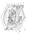
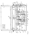
- a plate-shaped central body provided with threaded cylindrical supports 2 carried by a crankcase 3 constituting a support and a protection for the machine inner members.
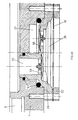
- a bellows having a corrugated cylindrical surface 5 made of thin soft rubber, located at the top of the central body 1 and secured to a cylindrical fixed base 6 forming part of the central body 1.
- the bellows 4 is closed by a rigid diaphragm 7 suitable to displace axially parallelly to itself in order to follow the volume changes occurring during the expanding and contracting of bellows 4.
- an electric motor 8 which causes the driving shaft 9 of a pumping apparatus to rotate, the latter including a first diaphragm pumping element 10 and a second diaphragm pumping element 11 acting in phase opposition.
- a pumping apparatus including a first diaphragm pumping element 10 and a second diaphragm pumping element 11 acting in phase opposition.
- an inlet pipe allowing gases coming from the exhaust valve of an apparatus producing anesthesia to get into the machine.
- This inlet pipe 12 is connected to a pipe fitting block 13 made of synthetic material, fastened in the vicinity of the side edge of the central body 1 lower surface.
- an outlet pipe of gases from the machine directly connected to a side surface of the central body 1.
- each of the two pumping elements is driven by a kinematic coupling comprising a connecting rod 15 and a crank 16.
- Each connecting rod 15 is fixed at its upper end integrally to the centerline of a rigid cap 17 mounted in the middle of a diaphragm 18 and at its lower end, by means of a bearing 19, to an eccentric pin 20 of the corresponding crank 16.
- Each crank 16 is fitted to the shaft 9 mounted on bearings 21 fixed to a support structure 22 which in turn is secured to the central body 1 by means of a stud bolt 23.
- Shaft 9 is rotated by the electric motor 8 disposed parallelly to it, which transmits motion by means of a toothed belt 24 mounted on gear wheels 25.
- Cranks 16 act on connecting rods 15 in phase opposition (180°).
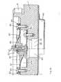
- FIGs. 12 and 13 it is indicated at 26 a first pumping chamber concerning the first pumping element 10 and at 27 a second pumping chamber concerning the second pumping element 11.
- Each pumping chamber 26 and 27, as can be seen in Figs. 12 and 13, is formed respectively in first 28 and second heads 29 rigidly fixed to the central body 1 by means of screws 30 and stud bolts 23.
- Pressure tight seals (0-Ring) 31 are provided which are interposed between each head 28 and 29 respectively and the central body 1.
- Each diaphragm 18 is peripherally sandwiched between the correspond ing head 28 or 29 and a corresponding flange 32 or 33 placed below.
- each intake valve which registers with the corresponding intake opening 35 of each pumping element 10 or 11 (in particular, Fig. 13 relates to the first pumping element 10).
- each delivery valve which registers with a corresponding delivery chamber 37, each being formed between the central body 1 and the heads 28 or 29.
- Each one of the two delivery chambers 37 communicates, downstream, with a by-pass valve 38 by means of an inlet pipe 39.
- This by-pass valve 38 enables one part of the pumped delivery to be discharged in bellows 4 again. In this way depressions in bellows 4 are restricted to physiologically non important values.
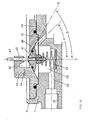
- the by-pass valve 38 placed in a recess 40 of the central body 1 symmetrically with respect to the pumping elements 10 and 11, comprises a cone-shaped valve head 41 which tapers upwardly and is provided with a stem 42 integral to it and operated by a lever mechanism placed above with respect to the by-pass valve 38 and inside the bellows 4.
- in said cover 44 is formed a first outlet pipe 46 which allows the communication between the by-pass valve 38 and the bellows 4.
- cover 46 In the central portion of cover 46 is a through hole 47 in which the stem 42 of the valve head 41 is introduced.
- the by-pass valve 38 is provided with a fixed seat 48 having a substantially cone-shaped surface formed in the inner upper portion of cover 44. This surface tapers in the same way as the valve head 41.
- the by-pass valve 38 is connected to the exterior of the machine by a second horizontal cylindrical outlet pipe 49 formed in the central body 1, this outlet pipe 49 having a larger diameter near the outer edge of the central body 1 and being provided with a thread 50 suitable to connect the outlet pipe 14 of gases from the machine.
- each inlet pipe 39 is positioned with respect to the valve head 41 so that the angle (a) determined by the geometrical intersection between the axis of symmetry of the valve head 41 and the longitudinal axis (R) of the inlet pipe 39 is equal to about 45° while the tapering (half angle (b) at the apex of the cone) of the valve head 41 and hence of the fixed seat 48 is equal to about 60°.
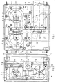
- FIG. 5 and 6 it is referenced 52 an arm oscillating about fixed hinges 53 applied to one end thereof 54, including a first pivot 55 to which is fixed a first preloaded spring 56 suitable to control the rotation which causes the lifting of the second end 57 of the oscillating arm 52.
- the second end 57 is connected at its upper end by means of a kinematic coupling with a pair of wheels 58, to the rigid diaphragm 7 of bellows 4.
- Fixed stops 59 formed on a suitably shaped bracket secured to the central body 1 by means of bolts 61, determine the lower limit of stroke of diaphragm 7 (completely lowered position of bellows 4) and at the same time the upper limit of stroke for the rotation of the oscillating arm 52.
- this oscillating arm 52 represents the balancing means suitable to reduce the resultant of the gravitational resilient and inertial forces (pressure stresses excepted) which act on the rigid diaphragm 7, so that the pressure stresses of bellows 4 and consequently of the machine can be improved.
- a first (mechanical) control and adjustment system including a lever mechanism 43 which is controlled by the axial movement of the rigid diaphragm 7 and acts in turn on the stem 42 of the by-pass valve 38.
- the lever mechanism 43 comprises a suitably shaped rigid lever 63 having one end thereof fixed in a fulcrum 64, where a second spring 65 is accommodated, situated on the upper part of cover 44 and the other end thereof kinematically coupled by means of a wheel 66 to the rigid diaphragm 7 of bellows 4.
- the rigid lever 63 is provided, intermediate between its ends, with a substantially cylindrical transverse sliding block 67 (Fig. 5) which is kinematically coupled by sliding to a suitably shaped curved plate which is concave on its upper part with respect to the sliding block 67.
- the plate 68 is provided with an arm 69 allowing the rotation thereof about a second pivot 70 placed on cover 44.
- the lower surface of plate 68 is kinematically coupled in turn to the upper end of the by-pass valve stem 42. Owing to its curved surface, the plate 68 is suitable to transmit the displacement of the rigid diaphragm 7 to the valve head 41 according to a predetermined law.
- the operating stress of diaphragm 7 necessary to open the by-pass valve 38 can be maintained almost constant. Consequently it helps very little in causing pressure perturbations inside the bellows 4.
- a second(electrical)control and regulation system comprising a variable inductance position transducer 72 of the rigid diaphragm 7.
- This transducer 72 comprises a hollow rigid rod 73 one end of which is integral to the diaphragm 7 to the centre of which it is secured and the other end thereof is partly introduced and slidable in a cylindrical port 74 formed in a fixed slide 75 including two distinct elements: one upper element 76 forming the fixed part of the position transducer 72 introduced in the central body, which is provided with a coil 77 electrically connected to the electric motor 8; a second cylindrical lower element 78 projecting downwardly from the central body 1 to which it is fastened by means of screws 79.
- a screw plug 80 closes the port 74 of the second element 78 at the bottom.
- a ferromagnetic insert 81 constituting the movable part of the position transducer 72.
- the coil 77 of enamelled copper wire, is so shaped that it allows the necessary swings of the electrical signal in connection with changes of position of the ferromagnetic insert 81 contained in the rigid rod 73.
- the position transducer 72 has to adjust the number of revolutions of the electric motor 8, suitable to actuate the pumping elements 10 and 1 1, according to the detected position of the rigid diaphragm 7 of bellows 4.
- a second safety valve suitable to avoid depressions in bellows 4, respectively placed upstream of the bellows 4 and downstream of the external area, with respect to the flow of the exterior air.
- the safety valves 82 and 83 located in the upper part of the central body 1, are disposed inside the bellows 4 symmetrically to the by-pass valve 38.
- the safety valves 82 and 83 which are exactly alike but placed inverted with respect to one another, are accommodated in first and second housings 84 and 85 respectively, both formed in the central body 1.
- Each one comprises a fixed truncated cone-shaped head 86 in line with the first and second housings 84 and 85 respectively and an elastic diaphragm 87 forming the movable member, which is essentially circular and in line with the corresponding head 86 having its outer edge fixed to the central body 1 by way of a flange 88 provided with screws 89.
- the elastic diaphragm 87 which achieves the opening and closing of the flow way of the corresponding valve 82 or 83,is provided with a circular central hole coaxial to the corresponding valve head 86 and lies in a plane normal to the axis of symmetry of the valve head 86.
- the above mentioned hole has its circular edge in contact with the valve head 86 which is provided on its upper part with an adjustment member 90 suit able to set the axial position thereof.
- the displacement of each elastic diaphragm 87 is automatically determined by differences in pressure (which are predetermined according to the axial position of the valve head 86 and to the elasticity of the material forming the diaphragm 87) between upstream and downstream of each valve 82 or 83.
- a manifold 91 connects the safety valves 82 and 83 with a quadrangular section passage 92 fixed at the lower part of the central body 1, which projects outwardly and communicates with the area outside the machine.
- the first safety valve 82 is designed to avoid the formation of high pressures in the bellows 4, due to a possible bad working of the pumping apparatus.
- the opening of the first valve 82 is adjustable within a field typically ranging between + 10 and + 50 mm H 2 0 of overpressure in the bellows 4 with respect to the surrounding atmosphere.
- the first valve 82 begins to discharge in the surrounding atmosphere through the manifold 91 and the passage 92. In this case the discharge appears acceptable as it can occur in the event of failure of the pumping apparatus only, with a reduction in the pumping capacity below the delivery values averagely discharged at that time from the apparatus producing anesthesia.
- the intervention of the first valve 82 can be preceded by an acoustic an d/ or visual warning generated by a pressure switch or by a suitable pressure transducer connected to the interior of bellows 4.
- the second safety valve 83 is designed, as previously described, to avoid the formation of depressions within the bellows 4 with respect to the atmosphere, which depressions are generated, in this case too, by the bad working of the pumping apparatus or of the by-pass valve 38.
- the second valve 83 can be calibrated, as to its opening, in a field typically ranging between - 10 and - 50 mm H 2 0 with respect to the atmosphere.
- the second valve 83 opens allowing air to enter and avoiding the depression to increase beyond the predetermined calibration value in bellows 4.
- a third safety valve located in the upper portion of the central body 1 within the bellows 4 and connecting one of the delivery chambers 37, which communicate with one another, to bellows 4.
- the third safety valve 93 which can normally be calibrated between 0,2 ⁇ 1 Bar, is designed for avoiding overpressures caused by casual obstructions downstream of the delivery chambers 37 of the pumping elements 10 and 11, as the same could damage the pumping apparatus. As the third safety valve 93 intervenes, it discharges within the bellows 4 directly, eventually generating a whistling which constitutes the acoustic warning thereof.
- a first inlet passage of gases in bellows 4 which communicates upstream with the pipe fitting block 13 (and hence with the inlet pipe 12), this passage being located peripherally in the vicinity of the cylindrical base inner edges 6.
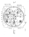
- the intake openings 35 of the pumping elements 10 and 11 are also disposed in the vicinity of the cylindrical base inner edge and their corresponding longitudinal axes are placed eccentrically (as shown in Fig. 8) with respect to the corresponding longitudinal axes of the pumping chambers 26 and 27 formed in the heads 28 and 29 which are accommodated in corresponding recesses 95 and 96 of the central body 1.
- Fig. 8 a first inlet passage of gases in bellows 4 which communicates upstream with the pipe fitting block 13 (and hence with the inlet pipe 12), this passage being located peripherally in the vicinity of the cylindrical base inner edges 6.
- the intake openings 35 of the pumping elements 10 and 11 are also disposed in the vicinity of the cylindrical base inner edge and their corresponding longitudinal axes are placed eccentrically (as shown in Fig. 8) with respect to
- inlet pipes 39 start from the recesses 95 and 96, these pipes being positioned according to the angle (a) in Fig. 14 of the by-pass valve 38.
- the valve is fitted in the recess 40 which is symmetrically positioned at the upper portion of the central body 1 with respect to the recesses 95 and 96 and eccentrically to the central vertical axis of the central body 1 (Fig. 7)
- Fig. 7 and particularly in Fig. 10 there is shown the recess 40 and the corresponding second cylindrical outlet pipe 49 as well as the thread 50 fitted for connection to the outlet pipe 14 of gases from the machine.
- On the opposite side with respect to the recess 40 as is shown in Fig. 7, are located the first and second seatings 34 and 85 for the first and second safety valves 82 and 83 respectively.
- These seatings 84 and 85 are connected to one another at the lower portion of the central body 1 by the V-shaped manifold 91 (Fig. 8) which is in communication with the quadrangular section passage 92.
- a second hole 98 is arranged at the opposite side with respect to the first inlet opening 94 of gases in the bellows 4 (Figs. 7, 8 and 9) in order to accommodate the third safety valve 93.
- the second hole 98 is in communication with one of the delivery chambers 37 by means of a horizontal drilling 99 completely interior to the central body 1 (see Fig. 7) which has a working clear ance 100 on the side wall of the central body 1 near the third safety valve 93.
- the working clearance 100 is closed on the outside by a plug 101 which avoids the escape from the machine of the possible flow coming from the delivery chamber 37, this flow being on the contrary conveyed towards the bellows 4 through the third safety valve 93.
- a plug 101 which avoids the escape from the machine of the possible flow coming from the delivery chamber 37, this flow being on the contrary conveyed towards the bellows 4 through the third safety valve 93.
- threaded holes housing corresponding screws 103 (Fig. 4) are referenced 102.
- bellows 4 increases its volume due only to the effect of the entering gases.
- gases contained in bellows 4 enter, through the intake valves 34, one of the pumping chambers 26 or 27 defined by the diaphragm 18.
- the diaphragm 18, urged by the connecting rod 15 is compressed, gases previously sucked reach the pumping pressure, cause the opening of the delivery valves 36 and come into the delivery chambers 37.
- gases can reach the outlet pipe 14 of the machine or they can be partly or completely recycled in bellows 4 through the first outlet pipe 46 in virtue of the gradual opening of the by-pass valve 38 which is controlled by the lever mechanism 43 responsive to the position of the rigid diaphragm 7 of bellows 4.
- the delivery flowing out of the machine is the difference between the delivery which has flowed into the bellows 4, which is dependent upon the number of revolutions of the motor 8 and in a less degree upon the delivery pressure, and the delivery which has returned into the bellows 4 through the by-pass valve 38.
Landscapes
- Health & Medical Sciences (AREA)
- Anesthesiology (AREA)
- Life Sciences & Earth Sciences (AREA)
- Engineering & Computer Science (AREA)
- Biodiversity & Conservation Biology (AREA)
- Ecology (AREA)
- Environmental & Geological Engineering (AREA)
- Environmental Sciences (AREA)
- Emergency Medicine (AREA)
- Pulmonology (AREA)
- Biomedical Technology (AREA)
- Heart & Thoracic Surgery (AREA)
- Hematology (AREA)
- Animal Behavior & Ethology (AREA)
- General Health & Medical Sciences (AREA)
- Public Health (AREA)
- Veterinary Medicine (AREA)
- Respiratory Apparatuses And Protective Means (AREA)
- Reciprocating Pumps (AREA)
Applications Claiming Priority (2)
| Application Number | Priority Date | Filing Date | Title |
|---|---|---|---|
| IT84965/80A IT1141839B (it) | 1980-10-20 | 1980-10-20 | Macchina atta alla evacuazione di gas provenienti da apparecchi di anestesia per inalazione |
| IT8496580 | 1980-10-20 |
Publications (1)
| Publication Number | Publication Date |
|---|---|
| EP0051045A1 true EP0051045A1 (de) | 1982-05-05 |
Family
ID=11326570
Family Applications (1)
| Application Number | Title | Priority Date | Filing Date |
|---|---|---|---|
| EP81830184A Withdrawn EP0051045A1 (de) | 1980-10-20 | 1981-10-05 | Gasspülvorrichtung für ein Inhalations-Anästhesiegerät |
Country Status (4)
| Country | Link |
|---|---|
| EP (1) | EP0051045A1 (de) |
| JP (1) | JPS57136460A (de) |
| ES (1) | ES8206191A1 (de) |
| IT (1) | IT1141839B (de) |
Cited By (2)
| Publication number | Priority date | Publication date | Assignee | Title |
|---|---|---|---|---|
| CN102188769A (zh) * | 2011-05-24 | 2011-09-21 | 深圳市科曼医疗设备有限公司 | 用于连接麻醉机和集成回路的转接联接器 |
| US8517021B2 (en) | 2009-09-29 | 2013-08-27 | Linde Aktiengesellschaft | Vacuum demand valve |
Families Citing this family (1)
| Publication number | Priority date | Publication date | Assignee | Title |
|---|---|---|---|---|
| NL8700389A (nl) * | 1987-02-17 | 1988-09-16 | Physio B V | Inrichting voor het beademen van patienten. |
Citations (4)
| Publication number | Priority date | Publication date | Assignee | Title |
|---|---|---|---|---|
| FR86888E (fr) * | 1962-10-25 | 1966-04-29 | Perfectionnements aux appareils de respiration artificielle | |
| US4004585A (en) * | 1975-11-18 | 1977-01-25 | Boehringer John R | Safety interface for anesthesia vacuum scavenging |
| US4176666A (en) * | 1976-06-01 | 1979-12-04 | Hovey Thomas C | Gas scavenger system |
| WO1980001044A1 (en) * | 1978-11-27 | 1980-05-29 | C Fischer | Gas scavenging exhaust system |
-
1980
- 1980-10-20 IT IT84965/80A patent/IT1141839B/it active
-
1981
- 1981-10-05 EP EP81830184A patent/EP0051045A1/de not_active Withdrawn
- 1981-10-16 ES ES506321A patent/ES8206191A1/es not_active Expired
- 1981-10-20 JP JP56166517A patent/JPS57136460A/ja active Pending
Patent Citations (4)
| Publication number | Priority date | Publication date | Assignee | Title |
|---|---|---|---|---|
| FR86888E (fr) * | 1962-10-25 | 1966-04-29 | Perfectionnements aux appareils de respiration artificielle | |
| US4004585A (en) * | 1975-11-18 | 1977-01-25 | Boehringer John R | Safety interface for anesthesia vacuum scavenging |
| US4176666A (en) * | 1976-06-01 | 1979-12-04 | Hovey Thomas C | Gas scavenger system |
| WO1980001044A1 (en) * | 1978-11-27 | 1980-05-29 | C Fischer | Gas scavenging exhaust system |
Cited By (2)
| Publication number | Priority date | Publication date | Assignee | Title |
|---|---|---|---|---|
| US8517021B2 (en) | 2009-09-29 | 2013-08-27 | Linde Aktiengesellschaft | Vacuum demand valve |
| CN102188769A (zh) * | 2011-05-24 | 2011-09-21 | 深圳市科曼医疗设备有限公司 | 用于连接麻醉机和集成回路的转接联接器 |
Also Published As
| Publication number | Publication date |
|---|---|
| IT1141839B (it) | 1986-10-08 |
| ES506321A0 (es) | 1982-08-16 |
| IT8084965A0 (it) | 1980-10-20 |
| ES8206191A1 (es) | 1982-08-16 |
| JPS57136460A (en) | 1982-08-23 |
Similar Documents
| Publication | Publication Date | Title |
|---|---|---|
| US6073630A (en) | Exhalation valve assembly | |
| US4278110A (en) | Demand responsive flow controller | |
| US4471775A (en) | Endotracheal tube cuff synchronizing system | |
| EP0347015A1 (de) | Beatmungssystem | |
| US3834383A (en) | Respiration apparatus with flow responsive control valve | |
| US5492115A (en) | Resuscitation breathing apparatus | |
| US4702240A (en) | Demand-responsive gas blending system for medical ventilator | |
| CN101808688A (zh) | 呼吸气体供应和共享系统及其方法 | |
| CN1202117A (zh) | 吸入装置 | |
| JP2017524100A (ja) | ベンチレータ・システム | |
| JP2016526639A (ja) | ベンチレータ・システム | |
| CN110464946A (zh) | 一种高频呼吸机系统及控制方法 | |
| US3251359A (en) | Automatic intermittent positive pressure ventilators | |
| US3995625A (en) | Inhalation devices | |
| EP0051045A1 (de) | Gasspülvorrichtung für ein Inhalations-Anästhesiegerät | |
| US4211220A (en) | Diving helmet assembly | |
| US2364626A (en) | Resuscitator | |
| JPS585058B2 (ja) | 呼吸装置で使用するための圧力制限弁 | |
| US3507297A (en) | Artificial respiration apparatus | |
| CN110384850B (zh) | 便携式辅助呼吸装置 | |
| CN87105720A (zh) | 复苏器 | |
| CN118807049B (zh) | 一种用于空运后送的人工气道气囊压力调节装置及方法 | |
| US3815593A (en) | Static respirator for artificial respiration | |
| JP2740511B2 (ja) | 患者用の呼吸装置 | |
| WO1991006335A1 (en) | Pneumatic demand oxygen valve |
Legal Events
| Date | Code | Title | Description |
|---|---|---|---|
| PUAI | Public reference made under article 153(3) epc to a published international application that has entered the european phase |
Free format text: ORIGINAL CODE: 0009012 |
|
| AK | Designated contracting states |
Designated state(s): AT BE CH DE FR GB LU NL SE |
|
| 17P | Request for examination filed |
Effective date: 19821029 |
|
| STAA | Information on the status of an ep patent application or granted ep patent |
Free format text: STATUS: THE APPLICATION IS DEEMED TO BE WITHDRAWN |
|
| 18D | Application deemed to be withdrawn |
Effective date: 19840229 |