EP0051055A1 - Vorrichtung zum Belüften der Taschen in einem Zylindertrockner - Google Patents
Vorrichtung zum Belüften der Taschen in einem Zylindertrockner Download PDFInfo
- Publication number
- EP0051055A1 EP0051055A1 EP81850193A EP81850193A EP0051055A1 EP 0051055 A1 EP0051055 A1 EP 0051055A1 EP 81850193 A EP81850193 A EP 81850193A EP 81850193 A EP81850193 A EP 81850193A EP 0051055 A1 EP0051055 A1 EP 0051055A1
- Authority
- EP
- European Patent Office
- Prior art keywords
- cylinder
- web
- wire
- air
- blowing
- Prior art date
- Legal status (The legal status is an assumption and is not a legal conclusion. Google has not performed a legal analysis and makes no representation as to the accuracy of the status listed.)
- Granted
Links
- 238000007664 blowing Methods 0.000 claims abstract description 60
- 238000001035 drying Methods 0.000 claims abstract description 23
- 230000001154 acute effect Effects 0.000 claims abstract description 6
- 230000002269 spontaneous effect Effects 0.000 claims description 13
- 238000000034 method Methods 0.000 claims description 11
- 230000035699 permeability Effects 0.000 claims description 8
- 210000000744 eyelid Anatomy 0.000 claims description 3
- 230000002093 peripheral effect Effects 0.000 claims 1
- 230000003134 recirculating effect Effects 0.000 claims 1
- 238000009423 ventilation Methods 0.000 description 6
- 238000005086 pumping Methods 0.000 description 3
- 230000003247 decreasing effect Effects 0.000 description 2
- 238000004140 cleaning Methods 0.000 description 1
- 230000001276 controlling effect Effects 0.000 description 1
- 238000007796 conventional method Methods 0.000 description 1
- 230000007423 decrease Effects 0.000 description 1
- 238000012423 maintenance Methods 0.000 description 1
- 230000001105 regulatory effect Effects 0.000 description 1
- 238000007789 sealing Methods 0.000 description 1
Images



Classifications
-
- D—TEXTILES; PAPER
- D21—PAPER-MAKING; PRODUCTION OF CELLULOSE
- D21F—PAPER-MAKING MACHINES; METHODS OF PRODUCING PAPER THEREON
- D21F5/00—Dryer section of machines for making continuous webs of paper
- D21F5/02—Drying on cylinders
- D21F5/04—Drying on cylinders on two or more drying cylinders
- D21F5/042—Drying on cylinders on two or more drying cylinders in combination with suction or blowing devices
- D21F5/046—Drying on cylinders on two or more drying cylinders in combination with suction or blowing devices using pocket ventilation systems
Definitions
- the present invention relates to a method of ventilating cylinder pockets in a cylinder dryer, which includes a plurality of heated cylinders about which a web-like material is taken zig-zag and is pressed against certain of the heated cylinder surfaces by means of an endless Fourdrinier wire.
- the cylinder pockets are formed between the cylinders, web and wire when the latter relinquishes contact with the web at a cylinder surface in order to pass over a return roll arranged between the cylinders, to once again make contact with the web at the cylinder surface next in line.
- the invention also relates to apparatus for carrying out the method.
- the drying wire consists of a high-permeability material allowing air passage
- a blowing means outside the cylinder pocket so that it extends over the width of the wire and is provided with blowing orifices for blowing drying air substantially at right angles to the plane of the wire.
- a high-permeability wire there is a heavy pump action, striving to pump in air into the pocket and also to pump air out of it.
- the quantity of air supplied to the pocket is, however, substantially greater than the quantity pumped out, which gives rise to an air current passing out through the ends of the pocket at right angles to the travelling direction of the wire.
- the difference between pumped-in air and pumped-out air becomes greater with increased speed of the wire, and the cross air current simultaneously increases.
- the cross air current will be so great that web flutter occurs within the critical end portions of the pocket, and attempts have been made to control this by altering the permeability of the wire and by moving the position of the return roll, thereby increasing the difference in quantity between pumped-in air and pumped-out air.
- the problems are intensified if a blowing box is placed outside the pocket to improve drying, this box blowing dry air at right angles to the wire, which further increases the quantity of air flowing into the pocket, whereas the pumped-out air quantity is kept practically constant for a given basic speed.
- the object of the present invention is to provide a method of controlling the air quantity blown into the cylinder pocket so that the difference in quantity between air pumped in and air pumped out through the criticial end cross section of the pocket will be as small as possible, whereby the risk of web flutter may be eliminated.
- This object is realized in accordance with the invention essentially in that a current of drying air is blown over the width of the wire against its surface facing away from the cylinder, in a direction forming an acute angle to the wire travel direction and with a directing component substantially counter-directed thereto, blowing taking place within an area where the wire relinquishes contact with the web, and for the purpose of reducing the spontaneous air inflow in the cylinder pocket brought on by the wire speed and texture, and in that for a given desired web speed the wire permeability is selected such that the difference between desired air inflow in the cylinder pocket and the spontaneous airflow out of the pocket generated by the wire speed and texture is sufficiently low for the air current thereby generated across the web not to exceed the speed at which web flutter occurs.
- the invention also relates to an apparatus for carrying out the method, and this apparatus is essentially characterized in that at least some of the blowing openings of the blowing box are directed such that drying air is caused to flow towards the wire in a direction forming an acute angle to the wire travelling direction and with a directing component substantially counter-directed thereto, and in that the blowing box is provided with means adapted to prevent an interface layer of moist air about the periphery of the return roller being introduced into the cylinder pocket by the rotation of the return roll.
- a material web 1 is transferred from a roll nip 2 in a wet section to the drying section, in which the web 1 is carried by a drying wire 3 in the form of an endless high-permeability Fourdrinier wire 3.
- the web is taken zig-zag between heated cylinders 4 and is pressed against the lower cylinders with the aid of the wire 3.
- Cylinder pockets 5 are thus formed between each.
- An inventive blowing box 9 is placed outside the cylinder pocket and is provided with blowing orifices 10, in the present case formed as louvre-type or eyelid perforations, directed such as to cause the drying air flowing out of the box to flow towards the wire 3 in a direction counter to that of the wire travel and to form an acute angle thereto.
- the orifices are disposed such that blowing on the wire 3 takes place within a zone 6 where the wire relinquishes contact with the web 1.
- sealing means 11 formed as strips of felt or brushes, made from temperature and moisture-proof material, lying against the circumference of the return roll 7 to prevent an interface layer of moist air around said circumference from being introduced into the cylinder pocket 5 through the wire 3 when the roll rotates.
- a conventional blowing box 9 will be seen from Fig. 1b and is similarly placed outside the cavity and provided with openings for blowing perpendicularly onto the wire 3.
- the blowing box structure is apparent from Figs. 2, 3 and 4.
- the box 9 thus has a substantially rectangular cross-section with a bevelled edge portion in which the eyelid perforations 10 are formed.
- the box is further divided into six sections, in the Figure running from 1 to 6.
- the drying air is individually suppliable to these sections via ducts 12, each of which has an adjustable valve 13, with the aid of which the air flow to the different sections can be regulated individually to obtain the desired drying profile of the web.
- the different sections are formed by means of an intermediate wall 14a extending substantially parallel to the plane of the wire 3 and up to cross walls 14b which divide the edge portion into sections.
- the blowing openings 10 are formed such that the airstream comes over the whole width of the wire and in a direction counter to the travelling direction thereof.
- the blowing box 9 can also be provided with conventional openings, as shown on Fig. 1b to permit at least a portion of the air to be flown perpendicularly onto the wire 3.
- the wire consists of high-permeability material which signifies that air can flow through it. However, this flow of air results in the occurence of a heavy pumping action during operation, which strives to pump air into the pocket and also to pump air out from it.
- the phenomenon is generally denoted as spontaneous ventilation of the cylinder pocket, and since pumping air into the pocket is more effective than pumping air out from it, more air comes in than goes out, which causes air to flow in the transverse direction of the web and go out through the end portions of the pocket. If this transverse air current becomes too great, it can cause flutter at the outer edges of the web, which is particularly dangerous if the superficial weight of the drying material is low and the machine speed high.
- the cause of a greater quantity of air being pumped in than is pumped out is connected with the different dimensions of the cylinders and return rollers, resulting in that the so-called pumping-in wedges 15 and 16 are more effective than the pumping-out wedges 17 and 18.
- the spontaneous ventilation of the cylinder pocket increases with increasing wire permeability, and naturally also with increasing machine speed.
- Fig. 5 the pumped-in air quantity is illustrated as a function of the pressure in a blowing box of a conventional kind for a given machine speed.
- the drying air is caused to flow out perpendicular to the wire and thereby also increase the total quantity of air flowing into the cylinder pocket.
- the letter A denotes the spontaneously pumped-in air quantity, which is thus constant for a given machine speed.
- the air quantity Q flowing into the cylinder pocket naturally depends on the pressure P in the blowing box and the relationship between these parameters gives a curve with the running coordinates QP.
- P 1 the total quantity of air pumped into the air pocket is equal to Q 1 .
- Fig. 6 is the corresponding curve for a blowing box with angled blowing according to the invention, where the value A represents the spontaneously pumped-in air quantity in the pocket, while the value B denotes the air quantity pumped spontaneously out from the pocket.
- the curve with the running coordinates QP denotes, as previously, the total quantity of air pumped into the pocket as a function of the pressure in the blowing box, and it will be seen from the Figure that the total quantity of air pumped in decreases with increasing blowing box air pressure.
- the values Q 2 and P 2 represent a working point lying a distance below the spontaneously pumped-in air quantity, and where the difference in quantity between the pumped-in and pumped-out air has been decreased with the aid of the air quantity blown angularly towards the wire. In practice this signifies that the airflow in the transverse direction of the web has decreased, and thereby the risk of web flutter has also been reduced. From the Figure it will also be seen that the curve cuts the line B at a certain value for the blowing box air pressure, the line B corresponding to the spontaneously pumped-out air quantity, and in such a position the difference between pumped-in and pumped-out air quantity has been completely eliminated.
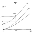
- Fig. 7 the airflows Q to and from the cylinder cavity have been illustrated as a function of the machine speed, here expressed in m/sec. similar to Fig. 5, the Figure illustrates the conditions in a blowing box with perpendicular blowing in accordance with the known art.
- the curve 2 represents spontaneously pumped-in air for a given type of wire, while curve 1 iilustrates the spontaneously pumped-out air quantity.
- the difference flow A-B constitutes the imbalance flow for spontaneous ventilation of the wire.
- the curve 3 represents total airflow pumped in when using a blowing box 19 for conventional blowing, and the difference flow Q 1 -B thus constitutes the imbalance between the pumped-in and pumped-out flow in the conventional art.
- Fig. 8 illustrates the same functions as in Fig. 7, although the wire has a higher permeability air, and blowing is done by a blowing box 9 in accordance with the invention.
- the curve 4 thus denotes the spontaneous pumping-in to the cylinder pocket, while the curve 5 represents the spontaneous pumping-out from the pocket.
- V m2 which is substantially higher than the machine speed V ml according to Fig. 7, the value A represents the spontaneous pumping-in, while the value B represents the spontanteous pumping-out.
- the airflow A-B thus constitutes the imbalance flow for spontaneous ventilation of the air pocket.
- the curve 6 shows the total pumping-in into the pocket while utilizing a method in accordance with the invention, and a point can thus be found for a given machine speed Vm2 where the total pumping-in Q 2 to the cylinder pocket matches the spontaneous pumped-out airflow which also signifies that balance has been obtained at the points Q 2 , V m2 .
- Two parameters can thus be varied to obtain a suitable balance point for a given machine speed, namely the pressure at the blowing box and the wire permeability.
- a greater air quantity to the pocket can only be provided by changing to a wire with greater permeability which allows a greater airflow through it. If the wire permeability increases, the spontaneous ventilation also increases, however, which signifies that the use of conventional technique would result in much too great imbalance flows and thereby risk for web flutter.
- the ventilation air quantity to the cylinder pocket can be reduced in accordance with the invention even if a highly permeable wire is used, at the same time keeping the imbalance flow between pumped-in and pumped-out air within acceptable values, i.e. so that the transverse velocity of the air current does not become too high and thereby cause web flutter.
- One consequence of the invention is that with the aid of this technique, the machine speed can be substantially increased without risk of web flutter occurring.
Landscapes
- Paper (AREA)
- Drying Of Solid Materials (AREA)
Priority Applications (1)
| Application Number | Priority Date | Filing Date | Title |
|---|---|---|---|
| AT81850193T ATE18582T1 (de) | 1980-10-23 | 1981-10-19 | Vorrichtung zum belueften der taschen in einem zylindertrockner. |
Applications Claiming Priority (2)
| Application Number | Priority Date | Filing Date | Title |
|---|---|---|---|
| SE8007440 | 1980-10-23 | ||
| SE8007440A SE444589B (sv) | 1980-10-23 | 1980-10-23 | Forfarande for ventilering av cylinderfickor i en cylindertork samt anordning for utforande av forfarandet |
Publications (2)
| Publication Number | Publication Date |
|---|---|
| EP0051055A1 true EP0051055A1 (de) | 1982-05-05 |
| EP0051055B1 EP0051055B1 (de) | 1986-03-12 |
Family
ID=20342063
Family Applications (1)
| Application Number | Title | Priority Date | Filing Date |
|---|---|---|---|
| EP81850193A Expired EP0051055B1 (de) | 1980-10-23 | 1981-10-19 | Vorrichtung zum Belüften der Taschen in einem Zylindertrockner |
Country Status (8)
| Country | Link |
|---|---|
| US (1) | US4477983A (de) |
| EP (1) | EP0051055B1 (de) |
| JP (1) | JPS57101277A (de) |
| AT (1) | ATE18582T1 (de) |
| CA (1) | CA1156829A (de) |
| DE (1) | DE3174068D1 (de) |
| SE (1) | SE444589B (de) |
| ZA (1) | ZA817066B (de) |
Cited By (4)
| Publication number | Priority date | Publication date | Assignee | Title |
|---|---|---|---|---|
| EP0090784A3 (en) * | 1982-03-25 | 1984-10-17 | Flakt Aktiebolag | Arrangement in cylinder drier |
| US4502231A (en) * | 1982-10-02 | 1985-03-05 | J. M. Voith, Gmbh | Air guide box for the dryer section of a paper making machine |
| US4553340A (en) * | 1983-05-30 | 1985-11-19 | Flakt Aktiebolag | Sealing device in a cylinder drier |
| US6209224B1 (en) | 1998-12-08 | 2001-04-03 | Kimberly-Clark Worldwide, Inc. | Method and apparatus for making a throughdried tissue product without a throughdrying fabric |
Families Citing this family (7)
| Publication number | Priority date | Publication date | Assignee | Title |
|---|---|---|---|---|
| FI76142C (fi) * | 1985-11-14 | 1988-09-09 | Valmet Oy | Fickventilationsfoerfarande och -anordning i en pappersmaskins maongcylindertork. |
| US4815220A (en) * | 1986-07-18 | 1989-03-28 | Beloit Corporation | Web transfer apparatus |
| FI82502C (fi) * | 1989-05-02 | 1991-03-11 | Valmet Paper Machinery Inc | Foerfarande och anordning i torkpartiet av en pappersmaskin foer att effektivera spetsdragningen av banan. |
| DE4015942C1 (de) * | 1990-05-18 | 1991-06-06 | J.M. Voith Gmbh, 7920 Heidenheim, De | |
| US5072527A (en) * | 1990-06-06 | 1991-12-17 | Loomie Leo S | Method and apparatus for conveying and tensioning a length of sheet material |
| US6260287B1 (en) * | 1997-08-08 | 2001-07-17 | Peter Walker | Wet web stability method and apparatus |
| FI20022231A0 (fi) | 2002-12-19 | 2002-12-19 | Metso Paper Inc | Järjestely kudoksen yhteydessä radan stabiloimiseksi |
Citations (8)
| Publication number | Priority date | Publication date | Assignee | Title |
|---|---|---|---|---|
| US1438211A (en) * | 1921-09-17 | 1922-12-12 | Skinner Bros Mfg Co | Paper-making machine |
| FR577836A (fr) * | 1924-02-27 | 1924-09-11 | Cie Sturtevant | Perfectionnements aux sécheries de papier, carton, tissu et de toutes matières en feuilles ou couches minces |
| US3110575A (en) * | 1961-01-25 | 1963-11-12 | Beloit Iron Works | Porous belt drying apparatus |
| US3376653A (en) * | 1966-12-06 | 1968-04-09 | Beloit Corp | Dryer ventilation |
| US3419203A (en) * | 1967-03-20 | 1968-12-31 | Beloit Corp | High speed paper making machine |
| US3504443A (en) * | 1967-03-28 | 1970-04-07 | Svenska Flaektfabriken Ab | Cylinder dryer with felt |
| GB1255920A (en) * | 1969-09-09 | 1971-12-01 | Valmet Oy | Improvements in devices for ventilating pockets in multicylinder driers |
| GB1321536A (en) * | 1970-06-03 | 1973-06-27 | Valmet Oy | Prevention of substantial net transverse air flows in multi- |
Family Cites Families (5)
| Publication number | Priority date | Publication date | Assignee | Title |
|---|---|---|---|---|
| US1595480A (en) * | 1922-01-20 | 1926-08-10 | Minton Ogden | Method and apparatus for drying sheet material |
| US3263344A (en) * | 1963-07-31 | 1966-08-02 | Stickle Steam Specialties Co I | Drying system for paper-making machinery and the like |
| US3320677A (en) * | 1965-02-12 | 1967-05-23 | Rice Barton Corp | Web drying apparatus |
| US3388479A (en) * | 1965-09-13 | 1968-06-18 | Thomas A Gardner | Pocket ventilator for web drying equipment |
| DE1511213A1 (de) * | 1965-09-13 | 1969-07-17 | Gardner Thomas A | Verfahren und Vorrichtung zur Belueftung von zu trocknendem Gewebe |
-
1980
- 1980-10-23 SE SE8007440A patent/SE444589B/sv not_active IP Right Cessation
-
1981
- 1981-10-13 ZA ZA817066A patent/ZA817066B/xx unknown
- 1981-10-14 US US06/311,463 patent/US4477983A/en not_active Expired - Fee Related
- 1981-10-19 DE DE8181850193T patent/DE3174068D1/de not_active Expired
- 1981-10-19 AT AT81850193T patent/ATE18582T1/de active
- 1981-10-19 EP EP81850193A patent/EP0051055B1/de not_active Expired
- 1981-10-21 JP JP56168507A patent/JPS57101277A/ja active Pending
- 1981-10-22 CA CA000388503A patent/CA1156829A/en not_active Expired
Patent Citations (8)
| Publication number | Priority date | Publication date | Assignee | Title |
|---|---|---|---|---|
| US1438211A (en) * | 1921-09-17 | 1922-12-12 | Skinner Bros Mfg Co | Paper-making machine |
| FR577836A (fr) * | 1924-02-27 | 1924-09-11 | Cie Sturtevant | Perfectionnements aux sécheries de papier, carton, tissu et de toutes matières en feuilles ou couches minces |
| US3110575A (en) * | 1961-01-25 | 1963-11-12 | Beloit Iron Works | Porous belt drying apparatus |
| US3376653A (en) * | 1966-12-06 | 1968-04-09 | Beloit Corp | Dryer ventilation |
| US3419203A (en) * | 1967-03-20 | 1968-12-31 | Beloit Corp | High speed paper making machine |
| US3504443A (en) * | 1967-03-28 | 1970-04-07 | Svenska Flaektfabriken Ab | Cylinder dryer with felt |
| GB1255920A (en) * | 1969-09-09 | 1971-12-01 | Valmet Oy | Improvements in devices for ventilating pockets in multicylinder driers |
| GB1321536A (en) * | 1970-06-03 | 1973-06-27 | Valmet Oy | Prevention of substantial net transverse air flows in multi- |
Cited By (4)
| Publication number | Priority date | Publication date | Assignee | Title |
|---|---|---|---|---|
| EP0090784A3 (en) * | 1982-03-25 | 1984-10-17 | Flakt Aktiebolag | Arrangement in cylinder drier |
| US4502231A (en) * | 1982-10-02 | 1985-03-05 | J. M. Voith, Gmbh | Air guide box for the dryer section of a paper making machine |
| US4553340A (en) * | 1983-05-30 | 1985-11-19 | Flakt Aktiebolag | Sealing device in a cylinder drier |
| US6209224B1 (en) | 1998-12-08 | 2001-04-03 | Kimberly-Clark Worldwide, Inc. | Method and apparatus for making a throughdried tissue product without a throughdrying fabric |
Also Published As
| Publication number | Publication date |
|---|---|
| US4477983A (en) | 1984-10-23 |
| SE444589B (sv) | 1986-04-21 |
| ZA817066B (en) | 1982-09-29 |
| SE8007440L (sv) | 1982-04-24 |
| CA1156829A (en) | 1983-11-15 |
| JPS57101277A (en) | 1982-06-23 |
| EP0051055B1 (de) | 1986-03-12 |
| ATE18582T1 (de) | 1986-03-15 |
| DE3174068D1 (en) | 1986-04-17 |
Similar Documents
| Publication | Publication Date | Title |
|---|---|---|
| FI68278C (fi) | Fickventilationsanordning foer en maongcylindertork i en pappersmaskin | |
| US4881327A (en) | Dryer section | |
| JP2795666B2 (ja) | 製紙機械の乾燥領域におけるウエブの保持方法並びに装置、及びこれに使用されるシリンダ | |
| US5471766A (en) | Method in contact-free air-drying of a material web as well as a nozzle-blow-box and a pulp dryer that make use of the method | |
| FI71371C (fi) | Foerfarande foer aostadkomma undertryck i en sektor av en valssamt en sugvals | |
| US4477983A (en) | Method of ventilating cylinder pockets in a cylinder dryer and apparatus for carrying out the method | |
| CA2092004C (en) | Method in contact-free air-drying of a material web as well as a nozzle-blow-box and a pulp dryer that make use of the method | |
| FI104099B (fi) | Menetelmä ja laite paperikoneella tai vastaavalla tai sen jälkikäsittelylaitteella pölyn poistamiseksi | |
| US6138380A (en) | Method and apparatus for controlling the temperature in a paper machine | |
| CA2012615C (en) | Method and device in the drying section of a coating machine or equivalent | |
| CA1295478C (en) | Device for stabilizing the run of a meterial web, specifically for stabilizing a paper web in the drying section of a paper machine | |
| SE461922B (sv) | Foerfarande och anordning i torkpartiet i en pappersmaskin vid styrning av banans aendfoeringsband | |
| KR960003186B1 (ko) | 건조펠트에 따라 웹의 에지를 유지하기 위한 장치 및 그의 방법 | |
| FI73259B (fi) | Foerfarande och anordning i cylindertorken av en pappersmaskin | |
| FI80103B (fi) | Foerfarande och anordning i cylindertorken av en pappersmaskin, vid vilken ett drag med dubbel vaevnad anvaends. | |
| FI82502B (fi) | Foerfarande och anordning i torkpartiet av en pappersmaskin foer att effektivera spetsdragningen av banan. | |
| US4899463A (en) | Method and device in a cylinder dryer of a paper machine | |
| US4686777A (en) | Preventing sheet flutter in paper web dryers | |
| US5152076A (en) | Method and device in a paper machine | |
| JP2804810B2 (ja) | ウェブの支持転向延展装置 | |
| US20020124429A1 (en) | Apparatus for ventilating a pocket of a dryer section of a paper machine | |
| SU767478A1 (ru) | Установка дл сушки полотна |
Legal Events
| Date | Code | Title | Description |
|---|---|---|---|
| PUAI | Public reference made under article 153(3) epc to a published international application that has entered the european phase |
Free format text: ORIGINAL CODE: 0009012 |
|
| AK | Designated contracting states |
Designated state(s): AT BE CH DE FR GB IT NL SE |
|
| 17P | Request for examination filed |
Effective date: 19821028 |
|
| RAP1 | Party data changed (applicant data changed or rights of an application transferred) |
Owner name: FLAEKT AKTIEBOLAG |
|
| GRAA | (expected) grant |
Free format text: ORIGINAL CODE: 0009210 |
|
| AK | Designated contracting states |
Kind code of ref document: B1 Designated state(s): AT BE CH DE FR GB IT LI NL SE |
|
| REF | Corresponds to: |
Ref document number: 18582 Country of ref document: AT Date of ref document: 19860315 Kind code of ref document: T |
|
| ITF | It: translation for a ep patent filed | ||
| REF | Corresponds to: |
Ref document number: 3174068 Country of ref document: DE Date of ref document: 19860417 |
|
| ET | Fr: translation filed | ||
| PGFP | Annual fee paid to national office [announced via postgrant information from national office to epo] |
Ref country code: AT Payment date: 19861021 Year of fee payment: 6 |
|
| PGFP | Annual fee paid to national office [announced via postgrant information from national office to epo] |
Ref country code: NL Payment date: 19861031 Year of fee payment: 6 |
|
| PLBE | No opposition filed within time limit |
Free format text: ORIGINAL CODE: 0009261 |
|
| STAA | Information on the status of an ep patent application or granted ep patent |
Free format text: STATUS: NO OPPOSITION FILED WITHIN TIME LIMIT |
|
| 26N | No opposition filed | ||
| PG25 | Lapsed in a contracting state [announced via postgrant information from national office to epo] |
Ref country code: AT Effective date: 19871019 |
|
| PG25 | Lapsed in a contracting state [announced via postgrant information from national office to epo] |
Ref country code: SE Effective date: 19871020 |
|
| PG25 | Lapsed in a contracting state [announced via postgrant information from national office to epo] |
Ref country code: LI Effective date: 19871031 Ref country code: CH Effective date: 19871031 Ref country code: BE Effective date: 19871031 |
|
| BERE | Be: lapsed |
Owner name: FLAKT A.B. Effective date: 19871031 |
|
| PG25 | Lapsed in a contracting state [announced via postgrant information from national office to epo] |
Ref country code: NL Effective date: 19880501 |
|
| NLV4 | Nl: lapsed or anulled due to non-payment of the annual fee | ||
| GBPC | Gb: european patent ceased through non-payment of renewal fee | ||
| PG25 | Lapsed in a contracting state [announced via postgrant information from national office to epo] |
Ref country code: FR Free format text: LAPSE BECAUSE OF NON-PAYMENT OF DUE FEES Effective date: 19880630 |
|
| REG | Reference to a national code |
Ref country code: CH Ref legal event code: PL |
|
| PG25 | Lapsed in a contracting state [announced via postgrant information from national office to epo] |
Ref country code: DE Effective date: 19880701 |
|
| REG | Reference to a national code |
Ref country code: FR Ref legal event code: ST |
|
| PG25 | Lapsed in a contracting state [announced via postgrant information from national office to epo] |
Ref country code: GB Effective date: 19881118 |
|
| EUG | Se: european patent has lapsed |
Ref document number: 81850193.4 Effective date: 19880707 |