EP0051091A1 - Arrangement de colonnes montantes pour systèmes de production - Google Patents
Arrangement de colonnes montantes pour systèmes de production Download PDFInfo
- Publication number
- EP0051091A1 EP0051091A1 EP80303869A EP80303869A EP0051091A1 EP 0051091 A1 EP0051091 A1 EP 0051091A1 EP 80303869 A EP80303869 A EP 80303869A EP 80303869 A EP80303869 A EP 80303869A EP 0051091 A1 EP0051091 A1 EP 0051091A1
- Authority
- EP
- European Patent Office
- Prior art keywords
- structural member
- joint
- diameter
- transition joint
- pounds
- Prior art date
- Legal status (The legal status is an assumption and is not a legal conclusion. Google has not performed a legal analysis and makes no representation as to the accuracy of the status listed.)
- Granted
Links
Images
Classifications
-
- E—FIXED CONSTRUCTIONS
- E21—EARTH OR ROCK DRILLING; MINING
- E21B—EARTH OR ROCK DRILLING; OBTAINING OIL, GAS, WATER, SOLUBLE OR MELTABLE MATERIALS OR A SLURRY OF MINERALS FROM WELLS
- E21B43/00—Methods or apparatus for obtaining oil, gas, water, soluble or meltable materials or a slurry of minerals from wells
- E21B43/01—Methods or apparatus for obtaining oil, gas, water, soluble or meltable materials or a slurry of minerals from wells specially adapted for obtaining from underwater installations
-
- E—FIXED CONSTRUCTIONS
- E21—EARTH OR ROCK DRILLING; MINING
- E21B—EARTH OR ROCK DRILLING; OBTAINING OIL, GAS, WATER, SOLUBLE OR MELTABLE MATERIALS OR A SLURRY OF MINERALS FROM WELLS
- E21B17/00—Drilling rods or pipes; Flexible drill strings; Kellies; Drill collars; Sucker rods; Cables; Casings; Tubings
- E21B17/01—Risers
- E21B17/017—Bend restrictors for limiting stress on risers
Definitions
- This invention relates to structural members, particularly but not exclusively to such a member adapted to form a fixed-bottom lower transition joint for a suspended pipe riser in an oil and gas production system.
- U.S. Patent No. 3,976,021, issued to Blenkarn et al. shows at FIG. 10 a riser having a transition joint with a straight taper between the upper and lower surfaces of the joint. That transition joint is not fixed at either its upper or lower surface. Blerkarn et al. does not disclose a curvilinear taper or an optimal design for such a taper.
- U.S. Patent No. 3,605,413, issued to Morgan discloses a riser having a rigidity varying lower portion which interconnects with an upper portion.
- Tne lower or base portion is disclosed to be made of steel and to have a non-uniform rigidity or section modulus wherein the maximum is at the foot of the base portion which connects to the seafloor structure, and wherein the minimum is at the top of the base portion which attaches to the upper portion.
- the base structure comprises a plurality of segments with each segment having a different outer diameter and wall thickness relative to every other segment. Although each segment has a different outer diameter, each has the same inner diameter. Each of these sections is interconnected so that the lowermost section has the largest diameter and each successively higher portion has a successively smaller outer diameter. Also, at the.point of interconnection of each section there is a taper which compensates for the different outer diameters of theconnectod segments. It is disclosed in the patent that such tapering could extend along an entire segment.
- the base portion comprises rigidity transition structures which prevent abrupt changes in the radius of curvature and act as stress transfer members between the upper portion of the riser and the upper sections of the base portion of the riser.
- the Morgan patent does indicate a transition joint comprising elements having different outer diameters, it fails to indicate a joint which has an outer surface which is continuously tapered from the top to the foot of the joint. Furthermore, the Morgan patent fails to disclose an optimally designed transition joint which has a nearly constant resultant stress along the length of its structure.
- U .S. Patent No. 3,794,849 issued to Perry et al., discloses a neutral buoyancy conductor connecting a floating power plant to stationary conductors which then connect the power plant to the shore.
- the neutral buoyancy conductor is indicated to have constant inner and outer diameters and to bend as a catenary to distribute stress resulting from various loads.
- the Perry et al. patent also discloses in its drawings vertical structures having continuously varying thicknesses from top to bottom. The specification indicates that these are poured concrete seawalls erected to form channels, but does not further define them.
- the Perry et al. patent fails to show a transition joint which has a continuously varying outer diameter from top to bottom which is optimally shaped to have nearly constant resultant stress along the length of the joint.
- U.S. Patent No. 1,706,246 issued to Miller discloses in its drawings vertical structures having a continuously varying or tapered outer surface. These vertical structures are walls which have linearly varying thicknesses from top to bottom. Howver, this patent fails to disclose optimum design criteria or any advantages for having the walls so tapered. Furthermore, this patent fails to disclose a transition joint having such a tapered contour.
- a structural member comprising: a first surface; a second surface spaced from said first surface; a third surface joining said first and second surfaces, said third surface having a continuous curvilinear taper from said second surface to said first surface, said taper being such that, for a given axial load, shear load and bending moment at said first surface, a resultant stress of said structural member is substantially constant between said first and second surfaces, and a fourth surface disposed concentrically within said third surface and extending between and joining to said first and second surfaces.
- the invention further provides a structural member as set forth above, which constitutes a transition joint for connecting a seafloor structure with a seasurface structure in an oil and gas production system, said first and second surfaces being top and bottom surfaces of said joint respectively, said third surface being an outer surface thereof, and said fourth surface defining a bore therethrough.
- the invention provides a structural member defined by a top planar surface having a predetermined diameter and a bottom planar surface which is parallel to and spaced from the top planar surface and which further has a diameter which is greater than the diameter of the top surface. Further defining the structural member is an outer surface which extends between and joins to the outer contours of the top and bottom planar surfaces. The outer surface has a contour with a continuous curvilinear taper from the larger diameter bottom surface to the smaller diameter top surface. Still further defining the structural member is an inner surface which extends longitudinally through the structural member to define a bore therethrough.
- the top surface predetermined diameter is predetermined according to both the outer diameter of the structure to which the top of the transition joint will be connected and the materials of which the joint and connecting structures are made.
- the degree of taper at any point along the outer surface between the top and bottom surfaces is defined by a diameter across the structural member at that point, which diameter is defined by the following equation:
- the transition joint has a substantially constant maximum resultant stress along the entire length of the joint. This provides an optimum transition joint in terms of economy of materials and ease of manufacture while retaining the desired strength against the stresses placed upon the transition joint which result from the bending moments created by loads imparted to the structure from ocean currents, waves and platform motions.
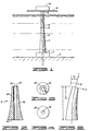
- FIG..1 diagrammatically shows a transition joint 2 according to the present invention positioned in its preferred use environment as a lower transition joint for a pipe riser with a fixed bottom.
- the preferred embodiment of the transition joint 2 comprises high strength steel and has a length of approximately fifty feet. This length is considered to be preferred because it provides ease of fabrication and yet is long enough to retain the advantages of a theoretically optimum transition joint which would extend the entire distance between the ultimate points to be joined.
- the transition joint 2 connects to a portion of a seafloor anchor base structure 4 which is positioned on a seafloor 6.
- the structure 4 includes, in part, a wellhead body and wellhead connector.
- the wellhead connector, to which the transition joint 2 connects at a base portion 8 may be either a hydraulically actuated connector or a threaded connector. It is at the base portion 8 that the bending moments resulting from loads on the transition joint 2 are the greatest, and thus this portion must be sufficiently large to withstand such stresses.
- the size and strength of the wellhead connector and the other components comprising the structure 4 are sufficiently larger than the base 8 of transition joint 2, so that base 8 may be considered to be fixed.
- a top portion 10 At the end of the transition joint 2 opposite the base portion 8 is a top portion 10. At the top portion 10 the loads are not as large as those at the base 8, so the top portion 10 need not be as large as the base portion 8. Also at the top portion 10 the transition. joint 2 connects with a pipe string 12 which in the FIG. 1 schematic representation is preferably a 9 5/8" tie- back string or riser. Pipe string 12 and transition joint 2 comprise a riser pipe assembly.
- the string 12 extends from the transition joint 2 upward to a surface platform 14.
- Platform 14 is a floating tension leg type platform.
- the string 12 connects with the platform 14 at a connection 16 which, in a preferred embodiment, is a tensioning jack.
- transport string 18 Located within the previously described subsurface structures is a transport string 18 which provides a means of access between the platform 14 and the region below the seafloor 6.
- the transport string 18 is a production riser which communicates the substances to be obtained from the subseafloor regions to the platform 14.
- Completing theFIG. 1 schematic is a member 20 which is disposed on the platform 14 and which is associated with the transport string 18 for controlling the dispersement of materials to and from the transport string 18 at the surface platform 14.
- the member 20 is preferably a completion tree.
- the transition joint 2- includes a structural member 30 which is defined by a first top planar surface 32, a second bottom planar surface 34, a third outer surface 36 and a fourth inner surface 38. Transition joint 2 is solid in the space defined between first, second, third and fourth surfaces 32, 34, 36 and 38.
- the top planar surface 32 is annular and has an outer contour which is defined by a predetermined diameter. This predetermined diameter is selected according to the diameter and composition of the string 12 with which the transition joint connects.
- Parallel to the top surface 32 is the bottom planar surface 34 which is also annular and has an outer contour which is defined by a diameter which is larger than the diameter defining the outer contour of the top surface 32.
- Top and bottom surfaces 32 and 34 are in spaced relation.
- the outer surface 36 extends between, joins to and circumscribes the outer contours of the top surface 32 and the bottom surface 34.
- the contour of the surface 36 has a curvilinear taper from the bottom surface 34 to the top surface 32.
- the inner surface 38 likewise extends between the top surface 32 and the bottom surface 34, but extends perpendicular thereto to thereby define a longitudinal bore through the structural member 30.
- FIG. 5 schematically represents the transition joint 2 under a load resulting from, for example, the ocean currents, waves or platform motions. These loads impart bending moments and other stresses to the joint 2 such as indicated in FIG. 5 by.an axial tension load T, a shear load S and a moment M.
- Equatinq (7) and (8) yields
- the optimum transition joint of the present invention will be obtained.
- Such as optimum joint has the requisite strength at its large base for withstanding applied loads, yet is optimally tapered to maintain a nearly constant resultant stress along the entire length of the joint thereby retaining the required strength throughout the structure but providing optimum economy of material and ease of manufacture. Therefore, the present invention has overcome the failures of the previously cited references to provide an optimally designed and manufactured transition joint.
- the present invertion overcomes the above- noted and other shortcomings of the prior art by providing a novel and improved transition joint.
- This joint is optimally constructed to withstand the loads applied to it in its ordinary use environment, and yet is economically and easily manufacturable because of its tapered contour whereby a nearly constant resultant stress comprising the outer fiber bending stress and tensile stress results along the entire length of the joint.
Landscapes
- Engineering & Computer Science (AREA)
- Life Sciences & Earth Sciences (AREA)
- Geology (AREA)
- Mining & Mineral Resources (AREA)
- Physics & Mathematics (AREA)
- Environmental & Geological Engineering (AREA)
- Fluid Mechanics (AREA)
- General Life Sciences & Earth Sciences (AREA)
- Geochemistry & Mineralogy (AREA)
- Mechanical Engineering (AREA)
- Earth Drilling (AREA)
Priority Applications (1)
| Application Number | Priority Date | Filing Date | Title |
|---|---|---|---|
| EP80303869A EP0051091B1 (fr) | 1980-10-30 | 1980-10-30 | Arrangement de colonnes montantes pour systèmes de production |
Applications Claiming Priority (1)
| Application Number | Priority Date | Filing Date | Title |
|---|---|---|---|
| EP80303869A EP0051091B1 (fr) | 1980-10-30 | 1980-10-30 | Arrangement de colonnes montantes pour systèmes de production |
Publications (2)
| Publication Number | Publication Date |
|---|---|
| EP0051091A1 true EP0051091A1 (fr) | 1982-05-12 |
| EP0051091B1 EP0051091B1 (fr) | 1986-02-26 |
Family
ID=8187285
Family Applications (1)
| Application Number | Title | Priority Date | Filing Date |
|---|---|---|---|
| EP80303869A Expired EP0051091B1 (fr) | 1980-10-30 | 1980-10-30 | Arrangement de colonnes montantes pour systèmes de production |
Country Status (1)
| Country | Link |
|---|---|
| EP (1) | EP0051091B1 (fr) |
Cited By (7)
| Publication number | Priority date | Publication date | Assignee | Title |
|---|---|---|---|---|
| GB2156407A (en) * | 1984-03-29 | 1985-10-09 | Univ London | Marine risers |
| GB2176521A (en) * | 1985-06-10 | 1986-12-31 | Elf Aquitaine | Limiting stress in risers |
| EP0209941A1 (fr) * | 1985-07-26 | 1987-01-28 | Single Buoy Moorings Inc. | Système d'amarrage |
| EP0296056A1 (fr) * | 1987-06-18 | 1988-12-21 | Institut Français du Pétrole | Elément à raideur variable pour pied de colonne de transfert |
| WO1994009245A1 (fr) * | 1992-10-08 | 1994-04-28 | Viking-Mjøndalen A.S | Raidisseur antiflexion |
| GB2317631A (en) * | 1996-09-30 | 1998-04-01 | Inst Francais Du Petrole | Production riser incorporating tensioning means and stiffening means |
| CN103982742A (zh) * | 2014-05-16 | 2014-08-13 | 大连理工大学 | 基于样条曲线的海洋柔性管缆防弯器 |
Citations (1)
| Publication number | Priority date | Publication date | Assignee | Title |
|---|---|---|---|---|
| US3794849A (en) * | 1972-08-18 | 1974-02-26 | Ite Imperial Corp | Power transmission system for connecting floating power plant to stationary conductors |
Family Cites Families (7)
| Publication number | Priority date | Publication date | Assignee | Title |
|---|---|---|---|---|
| US1706246A (en) * | 1928-03-03 | 1929-03-19 | Dravo Contracting Company | Method of building piers |
| US3414067A (en) * | 1957-03-28 | 1968-12-03 | Shell Oil Co | Drilling |
| US3307624A (en) * | 1963-05-22 | 1967-03-07 | Pan American Petroleum Corp | Load-supporting structure, particularly for marine wells |
| US3512811A (en) * | 1968-01-22 | 1970-05-19 | Exxon Production Research Co | Pile-to-jacket connector |
| US3559410A (en) * | 1968-07-30 | 1971-02-02 | Pan American Petroleum Corp | System for relieving stress at the top and bottom of vertical tubular members in vertically moored platforms |
| US3605413A (en) * | 1969-10-24 | 1971-09-20 | North American Rockwell | Riser with a rigidity varying lower portion |
| US3976021A (en) * | 1975-09-08 | 1976-08-24 | Standard Oil Company (Indiana) | Installation of vertically moored platform |
-
1980
- 1980-10-30 EP EP80303869A patent/EP0051091B1/fr not_active Expired
Patent Citations (1)
| Publication number | Priority date | Publication date | Assignee | Title |
|---|---|---|---|---|
| US3794849A (en) * | 1972-08-18 | 1974-02-26 | Ite Imperial Corp | Power transmission system for connecting floating power plant to stationary conductors |
Cited By (12)
| Publication number | Priority date | Publication date | Assignee | Title |
|---|---|---|---|---|
| GB2156407A (en) * | 1984-03-29 | 1985-10-09 | Univ London | Marine risers |
| GB2176521A (en) * | 1985-06-10 | 1986-12-31 | Elf Aquitaine | Limiting stress in risers |
| EP0209941A1 (fr) * | 1985-07-26 | 1987-01-28 | Single Buoy Moorings Inc. | Système d'amarrage |
| US4735472A (en) * | 1985-07-26 | 1988-04-05 | Single Buoy Moorings Inc. | Mooring system |
| EP0296056A1 (fr) * | 1987-06-18 | 1988-12-21 | Institut Français du Pétrole | Elément à raideur variable pour pied de colonne de transfert |
| FR2616858A1 (fr) * | 1987-06-18 | 1988-12-23 | Inst Francais Du Petrole | Element a raideur variable pour pied de colonne de transfert |
| WO1994009245A1 (fr) * | 1992-10-08 | 1994-04-28 | Viking-Mjøndalen A.S | Raidisseur antiflexion |
| GB2286414A (en) * | 1992-10-08 | 1995-08-16 | Viking Mjondalen As | Bending stiffener |
| GB2286414B (en) * | 1992-10-08 | 1996-03-06 | Viking Mjondalen As | Bending stiffener |
| GB2317631A (en) * | 1996-09-30 | 1998-04-01 | Inst Francais Du Petrole | Production riser incorporating tensioning means and stiffening means |
| GB2317631B (en) * | 1996-09-30 | 2001-02-21 | Inst Francais Du Petrole | Production riser fitted with an appropriate stiffener and an individual float |
| CN103982742A (zh) * | 2014-05-16 | 2014-08-13 | 大连理工大学 | 基于样条曲线的海洋柔性管缆防弯器 |
Also Published As
| Publication number | Publication date |
|---|---|
| EP0051091B1 (fr) | 1986-02-26 |
Similar Documents
| Publication | Publication Date | Title |
|---|---|---|
| US4256417A (en) | Variable stiffness lower joint for pipe riser with fixed bottom | |
| KR100493496B1 (ko) | 연장된 베이스형 텐션 레그 플랫폼 하부구조체 | |
| EP0195552A2 (fr) | Colonne en tube d'acier rempli de béton et son procédé de fabrication | |
| US4117690A (en) | Compliant offshore structure | |
| CA1147214A (fr) | Systeme d'interconnexion de flotteurs marins | |
| KR100382894B1 (ko) | 반잠수되며이동가능한조립식해상플랫폼지지물 | |
| US5094567A (en) | Flexible column from composite material | |
| US3605413A (en) | Riser with a rigidity varying lower portion | |
| US5044828A (en) | Support tower for offshore well | |
| US4705430A (en) | Composite leg platform | |
| EP0057082B1 (fr) | Arceau composite de soutènement | |
| US4363568A (en) | Conductors for a guyed tower and method for installing same | |
| EP0051091A1 (fr) | Arrangement de colonnes montantes pour systèmes de production | |
| GB2168098A (en) | Fixed marine steel structure and procedure for assembly of the structure | |
| EP0179776B1 (fr) | Structure de plate-forme a entretoises multiples de haute mer | |
| US3668876A (en) | Offshore tower apparatus and method | |
| AU692173B2 (en) | Offshore tower structure and method of installation | |
| EP0191992B1 (fr) | Elément d'amarrage composite pour structures en mer profonde | |
| AU744021B2 (en) | Method of installing conduit or the like on mountain surface using steel cable | |
| US4797034A (en) | Oscillating marine platform with a rigid base | |
| IE841135L (en) | Marine structure | |
| CA1145149A (fr) | Articulation de rigidite variable pour colonne hydraulique montante ancree par le bas | |
| US6527481B1 (en) | Cylindrical steel core caisson | |
| CN110735394A (zh) | 索塔结构及其建造方法 | |
| EP0312198B1 (fr) | Pieu, en particulier pieu d'ancrage |
Legal Events
| Date | Code | Title | Description |
|---|---|---|---|
| PUAI | Public reference made under article 153(3) epc to a published international application that has entered the european phase |
Free format text: ORIGINAL CODE: 0009012 |
|
| 17P | Request for examination filed |
Effective date: 19820112 |
|
| AK | Designated contracting states |
Designated state(s): FR GB NL |
|
| GRAA | (expected) grant |
Free format text: ORIGINAL CODE: 0009210 |
|
| AK | Designated contracting states |
Designated state(s): FR GB NL |
|
| ET | Fr: translation filed | ||
| PLBE | No opposition filed within time limit |
Free format text: ORIGINAL CODE: 0009261 |
|
| STAA | Information on the status of an ep patent application or granted ep patent |
Free format text: STATUS: NO OPPOSITION FILED WITHIN TIME LIMIT |
|
| 26N | No opposition filed | ||
| PGFP | Annual fee paid to national office [announced via postgrant information from national office to epo] |
Ref country code: FR Payment date: 19921009 Year of fee payment: 13 |
|
| PGFP | Annual fee paid to national office [announced via postgrant information from national office to epo] |
Ref country code: NL Payment date: 19921031 Year of fee payment: 13 |
|
| PGFP | Annual fee paid to national office [announced via postgrant information from national office to epo] |
Ref country code: GB Payment date: 19930917 Year of fee payment: 14 |
|
| PG25 | Lapsed in a contracting state [announced via postgrant information from national office to epo] |
Ref country code: NL Effective date: 19940501 |
|
| NLV4 | Nl: lapsed or anulled due to non-payment of the annual fee | ||
| PG25 | Lapsed in a contracting state [announced via postgrant information from national office to epo] |
Ref country code: FR Effective date: 19940630 |
|
| REG | Reference to a national code |
Ref country code: FR Ref legal event code: ST |
|
| PG25 | Lapsed in a contracting state [announced via postgrant information from national office to epo] |
Ref country code: GB Effective date: 19941030 |
|
| GBPC | Gb: european patent ceased through non-payment of renewal fee |
Effective date: 19941030 |